EP0620075A2 - Arc welding torch for welding under protective gas - Google Patents
Arc welding torch for welding under protective gas Download PDFInfo
- Publication number
- EP0620075A2 EP0620075A2 EP94104464A EP94104464A EP0620075A2 EP 0620075 A2 EP0620075 A2 EP 0620075A2 EP 94104464 A EP94104464 A EP 94104464A EP 94104464 A EP94104464 A EP 94104464A EP 0620075 A2 EP0620075 A2 EP 0620075A2
- Authority
- EP
- European Patent Office
- Prior art keywords
- receptacle
- contact tip
- welding torch
- arc welding
- contact
- Prior art date
- Legal status (The legal status is an assumption and is not a legal conclusion. Google has not performed a legal analysis and makes no representation as to the accuracy of the status listed.)
- Granted
Links
Images


Classifications
-
- B—PERFORMING OPERATIONS; TRANSPORTING
- B23—MACHINE TOOLS; METAL-WORKING NOT OTHERWISE PROVIDED FOR
- B23K—SOLDERING OR UNSOLDERING; WELDING; CLADDING OR PLATING BY SOLDERING OR WELDING; CUTTING BY APPLYING HEAT LOCALLY, e.g. FLAME CUTTING; WORKING BY LASER BEAM
- B23K9/00—Arc welding or cutting
- B23K9/24—Features related to electrodes
- B23K9/28—Supporting devices for electrodes
- B23K9/29—Supporting devices adapted for making use of shielding means
- B23K9/291—Supporting devices adapted for making use of shielding means the shielding means being a gas
- B23K9/295—Supporting devices adapted for making use of shielding means the shielding means being a gas using consumable electrode-wire
Definitions
- the invention relates to an arc welding torch according to the preamble of claim 1.
- the components of the welding torch namely the contact tip, an insert which may be present in the contact tip and the gas nozzle, are detachably connected to their corresponding receiving parts.
- the invention is an object of the invention to provide an arc welding torch of the type mentioned, in which the attachment of the components mentioned, namely the contact tip, and any insert and a gas nozzle, is designed so that for good heat conduction and yet for easy and quick attachment and a corresponding release is provided if this is desired.
- the rotary cone according to the invention can therefore be used in different ways.
- a rotating cone can be provided between one or more of the components mentioned. It is also possible to use a rotating cone for fastening one of the components mentioned, and to fasten the other components in a conventional manner by means of a thread or a plug-in cone.
- the rotary cone is advantageously used for all existing components for which such a type of fastening is advantageous, taking into account the desired heat conduction and releasable fastening.
- longitudinal slots can be provided in the area of the contact surfaces which are used to conduct protective gas. These longitudinal slots can be introduced separately, or can simply be the spaces that remain when turning in the closing direction.
- the principle of the rotating cone, formed by the spiral segment surfaces is not only directly in the welding torch in the area of the welding technology mentioned here, i.e. can be used in the welding tool, but also with quick-action couplings for the transmission of current and / or heat in the supply line between the welding current source and the welding torch, the separation point being able to be provided on the welding machine, in the hose package or in the welding gun head itself.
- the welding torch has a contact tip 1 which is fastened on a receptacle 2.
- the coolant flows through a pipe 3 and a pipe 4 to a coolant ring channel 5 in the receptacle 2 and back again.
- the contact tip is fastened to the receptacle 2 by means of a rotating cone, which is formed by spiral contact surfaces 7, 8 is formed, as is best seen when looking at Figs. 2 and 3.
- These contact surfaces 7 and 8 have, as a common center, the center line of the welding wire bore 9 which can be seen in cross section.
- the segment surfaces 7 and 8 are always equally spaced from the center line of the welding wire bore 9, ie they practically form cylindrical surfaces.
- the contact tip 1 can be plugged onto the receptacle 2 unhindered.
- a small angle, which is shown in FIG. 3, is then used for fastening.
- the segment surfaces 7 and 8 come into contact with one another, ie they "wedge". A large-area contact is created, which ensures good heat conduction and secure fastening, which can be released again at the same time.
- the contact tip surrounds the coolant ring channel 5 with its end facing the tube 3, 4, the rotating cone connection in this area ensuring good heat transfer and secure attachment.
- an insert 10 can be secured in an inner bore of the contact tip, as shown in FIG. 1.
- This insert is a wearing part that can be replaced.
- the insert can therefore be designed specifically for its task of being a wearing part, i.e. consist of appropriate materials.
- the insert is advantageously fastened on the same principle as the contact tip, namely with the aid of a rotating cone which is designed as shown in FIGS. 6 and 7.
- the spiral segment surfaces are designated 14 and 15.
- an attack 11 is provided for a tool. This allows the fixed Connection can be achieved by slight twisting, that is to assume the position shown in Fig. 7. Conversely, this connection can be released again when the insert is to be replaced.
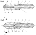
- the embodiment according to FIG. 4 shows a contact tip 1, which is also attached to the receptacle 2 with the aid of a rotating cone (segment surfaces 7, 8).
- the insert 10 is fastened differently than in the embodiment according to FIG. 1, namely with the aid of a plug-in cone and a thread 12 in the front area.
- the insert is fastened with the aid of a rotating cone (segment surfaces 14, 15).
- the contact tip 1 is fastened to the receptacle 2 with the aid of a plug-in cone connection 18, 19 and a thread 6.
- a transverse bore 13 is provided for the passage of protective gas.
- FIG. 8 basically corresponds to that according to FIG. 1, but with a gas nozzle 16 attached to a tubular gas nozzle receptacle 23, again with the aid of a rotating cone which corresponds to that described above and is shown in FIGS. 9 and 10 .
- the segment surfaces are designated 20 and 21.
- the gas nozzle 16 is electrically isolated from the tubes 3 and 4 by an insulating ring 22.
- the protective gas line takes place through an annular channel on the outside of the tube 4 to openings 17 and from there into the area of the gas nozzle 16, ie into the annular space between the gas nozzle 16 and the contact tip 1.
- a second cooling circuit 25 is provided, which cools the gas nozzle receptacle 23 serves.
- the inner part is formed in its outer contour (segment surface 15) with three spiral segments of 120 ° each.
- the distance of the surface line of each segment from a common center per angular step increases by a certain value in relation to the radius.
- an inclined plane would result as a development, the slope in the above-mentioned embodiments is approximately 5%.
- the inner contour (segment surface 14) of the outer part (contact tip 1) is designed in the same way, but with an initial value enlarged by a certain gap.
- the size of the gap is selected so that the inner part can be easily inserted into the outer part, taking into account the manufacturing tolerances.
- Both the inner and outer part are designed with a cylindrical cross-section that is constant in their length.
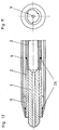
- FIGS. 11 and 12 differs from the embodiments illustrated in the other figures in that the receptacle 2 with the coolant ring channel 5 surrounds the contact tip on the outside, so that the contact surfaces, which are designed as a rotating cone with the spiral segment surfaces, are on the inside of the holder and on the outside of the contact tip.
- the receptacle 2 consists of tubes 3, 4, which are assembled by solder rings 26.
- the contact tip is surrounded over most of its longitudinal extent by the coolant ring channel 5, so that very good heat dissipation via the rotating cone and a short heat transfer surface in the radial direction are ensured.
Abstract
Description
Die Erfindung betrifft einen Lichtbogenschweißbrenner nach dem Oberbegriff des Anspruches 1.The invention relates to an arc welding torch according to the preamble of
Ein Lichtbogenschweißbrenner der vorstehend genannten Art ist aus der DE-PS 26 31 742 bekannt.An arc welding torch of the type mentioned above is known from DE-PS 26 31 742.
Bei derartigen Lichtbogenschweißbrennern besteht seit langem das Bestreben, die im Bereich der Kontaktspitze erzeugte Wärme möglichst schnell abzuleiten und zwar in den Bereich des Schweißbrenners, in dem das Kühlmittel strömt. Dieses wird im Falle des Lichtbogenschweißbrenners nach der DE-PS 26 31 742 dadurch angestrebt, daß die Kontaktspitze mit Hilfe eines Gewindes auf den den Kühlmittelkreislauf enthaltenden Abschnitt der Aufnahme außen aufgeschraubt ist, so daß Berührungsflächen vorhanden sind, die die Wärme von der Kontaktspitze radial nach innen in Richtung auf das Kühlmittel ableiten.In such arc welding torches there has long been an effort to dissipate the heat generated in the area of the contact tip as quickly as possible, specifically in the area of the welding torch in which the coolant flows. This is aimed in the case of the arc welding torch according to DE-PS 26 31 742 in that the contact tip is screwed onto the portion of the receptacle containing the coolant circuit with the aid of a thread, so that there are contact surfaces which radiate the heat from the contact tip radially Drain inside towards the coolant.
Die Bauteile des Schweißbrenners, nämlich die Kontaktspitze, ein gegebenenfalls vorhandener Einsatz in der Kontaktspitze und die Gasdüse, sind lösbar mit ihren entsprechenden Aufnahmeteilen verbunden.The components of the welding torch, namely the contact tip, an insert which may be present in the contact tip and the gas nozzle, are detachably connected to their corresponding receiving parts.
Der Erfindung liegt nun die Aufgabe zugrunde, einen Lichtbogenschweißbrenner der eingangs genannten Art zu schaffen, bei dem die Befestigung der genannten Bauteile, nämlich der Kontaktspitze, sowie eines ggf. vorhandenen Einsatzes und einer Gasdüse, so ausgebildet ist, daß für eine gute Wärmeleitung und dennoch für eine einfache und schnelle Befestigung und ein entsprechendes Lösen gesorgt wird, wenn dieses erwünscht ist.The invention is an object of the invention to provide an arc welding torch of the type mentioned, in which the attachment of the components mentioned, namely the contact tip, and any insert and a gas nozzle, is designed so that for good heat conduction and yet for easy and quick attachment and a corresponding release is provided if this is desired.
Diese Aufgabe wird grundsätzlich durch das Kennzeichen des Anspruches 1 gelöst, wobei die Ansprüche 2, 3, 4 und 5 auf besondere Ausgestaltungen gerichtet sind.This object is basically achieved by the characterizing part of
Der erfindungsgemäße Drehkonus kann also in unterschiedlicher Weise zum Einsatz kommen.The rotary cone according to the invention can therefore be used in different ways.
Bei welchen Bauteilen der Drehkonus auch immer vorgesehen ist, stellt er eine sehr vorteilhafte Maßnahme dar, um einerseits für eine schnelle Befestigung und ggf. Lösung, und andererseits für eine gute Wärmeleitung zu sorgen, da eine großflächige Berührung vorliegt. Es findet zwischen den Segmentflächen keine Linienberührung, sondern eine Flächenberührung statt, so daß für eine entsprechend gute Wärmeleitung gesorgt ist.Whatever components the rotary cone is provided for, it represents a very advantageous measure, on the one hand to ensure quick attachment and possibly solution, and on the other hand to ensure good heat conduction, since there is extensive contact. There is no line contact between the segment surfaces, but a surface contact, so that a correspondingly good heat conduction is ensured.
Je nachdem, wie der Schweißbrenner ausgebildet ist, kann ein Drehkonus zwischen einem oder mehreren der genannten Bauteile vorgesehen sein. Es ist auch möglich, einen Drehkonus zur Befestigung eines der genannten Bauteile einzusetzen, und die anderen Bauteile auf herkömmliche Weise durch ein Gewinde oder einen Steckkonus zu befestigten.Depending on how the welding torch is designed, a rotating cone can be provided between one or more of the components mentioned. It is also possible to use a rotating cone for fastening one of the components mentioned, and to fasten the other components in a conventional manner by means of a thread or a plug-in cone.
In vorteilhafter Weise findet der Drehkonus aber für sämtliche vorhandenen Bauteile Verwendung, für die unter Berücksichtigung der erwünschten Wärmeleitung und lösbaren Befestigung eine solche Befestigungsart von Vorteil ist.However, the rotary cone is advantageously used for all existing components for which such a type of fastening is advantageous, taking into account the desired heat conduction and releasable fastening.
In vorteilhafter Weise können, wie in Anspruch 8 angegeben, Längsschlitze im Bereich der Berührungsflächen vorgesehen sein, die der Leitung von Schutzgas dienen. Diese Längsschlitze können gesondert eingebracht sein, oder einfach diejenigen freigebliebenen Räume sein, die beim Drehen in Schließrichtung entstehen.Advantageously, as stated in
Grundsätzlich ist das Prinzip des Drehkonus, gebildet durch die spiralförmigen Segmentflächen, im Bereich der hier angesprochenen Schweißtechnik nicht nur direkt im Schweißbrenner, d.h. im Schweißwerkzeug, einsetzbar, sondern auch bei Schnellkupplungen zur Übertragung von Strom und/oder Wärme in der Zuleitung zwischen Schweißstromquelle und Schweißbrenner, wobei die Trennstelle an der Schweißmaschine, im Schlauchpaket oder im Schweißpistolenkopf selbst vorgesehen sein kann.Basically, the principle of the rotating cone, formed by the spiral segment surfaces, is not only directly in the welding torch in the area of the welding technology mentioned here, i.e. can be used in the welding tool, but also with quick-action couplings for the transmission of current and / or heat in the supply line between the welding current source and the welding torch, the separation point being able to be provided on the welding machine, in the hose package or in the welding gun head itself.
Im folgenden wird die Erfindung unter Hinweis auf die Zeichnung anhand verschiedener Ausführungsbeispiele näher erläutert.The invention is explained in more detail below with reference to the drawing using various exemplary embodiments.
Es zeigt:
- Fig. 1
- einen Längsschnitt durch eine erste Ausführungsform eines Schweißbrenners nach der Erfindung;
- Fig. 2
- einen Querschnitt gemäß der Linie C-C der Fig. 1, und zwar nach dem Aufschieben der Kontaktspitze, aber vor dem Verdrehen;
- Fig. 3
- einen der Fig. 2 entsprechenden Querschnitt, jedoch nach dem Verdrehen;
- Fig. 4
- einen Längsschnitt durch eine andere Ausführungsform;
- Fig. 5
- einen Längsschnitt durch eine weitere Ausführungsform;
- Fig. 6
- einen Querschnitt im extrem vergrößerten Maßstab gemäß der Linie A-A der Fig. 5 nach dem Einschieben des Einsatzes;
- Fig. 7
- einen der Fig. 6 entsprechenden Querschnitt, jedoch nach dem Verdrehen des Einsatzes;
- Fig. 8
- einen Längsschnitt durch eine weitere Ausführungsform eines Schweißbrenners nach der Erfindung mit einer Gasdüse;
- Fig. 9
- einen Querschnitt gemäß der Linie B-B der Fig. 8 im vergrößerten Maßstab nach dem Aufschieben der Gasdüse;
- Fig.10
- einen der Fig. 9 entsprechenden Querschnitt, jedoch nach dem Verdrehen der Gasdüse,
- Fig. 11
- eine Vorderansicht einer weiteren Ausführungsform; und
- Fig. 12
- einen Längsschnitt durch die Ausführungsform entsprechend Fig. 11 mit innenliegender Kontaktspitze.
- Fig. 1
- a longitudinal section through a first embodiment of a welding torch according to the invention;
- Fig. 2
- a cross-section along the line CC of Figure 1, namely after sliding the contact tip, but before twisting.
- Fig. 3
- a cross section corresponding to Figure 2, but after twisting.
- Fig. 4
- a longitudinal section through another embodiment;
- Fig. 5
- a longitudinal section through a further embodiment;
- Fig. 6
- a cross-section on an extremely enlarged scale along the line AA of Figure 5 after inserting the insert.
- Fig. 7
- a cross section corresponding to Figure 6, but after twisting the insert.
- Fig. 8
- a longitudinal section through a further embodiment of a welding torch according to the invention with a gas nozzle;
- Fig. 9
- a cross section along the line BB of Figure 8 on an enlarged scale after sliding the gas nozzle.
- Fig. 10
- 9 shows a cross section corresponding to FIG. 9, but after turning the gas nozzle,
- Fig. 11
- a front view of another embodiment; and
- Fig. 12
- a longitudinal section through the embodiment corresponding to FIG. 11 with an internal contact tip.
Gleiche Teile der verschiedenen Ausführungen sind mit gleichen Bezugszeichen bezeichnet.The same parts of the different designs are denoted by the same reference numerals.
Von dem in der Zeichnung dargestellten Schweißbrenner sind nur die wesentlichen Bauteile dargestellt. Der Schweißbrenner weist eine Kontaktspitze 1 auf, die auf einer Aufnahme 2 befestigt ist. Das Kühlmittel strömt durch ein Rohr 3 und ein Rohr 4 zu einem Kühlmittelringkanal 5 in der Aufnahme 2 und wieder zurück.Only the essential components of the welding torch shown in the drawing are shown. The welding torch has a
Bei der Ausführungsform nach den Fig. 1 bis 3 ist die Kontaktspitze an der Aufnahme 2 mit Hilfe eines Drehkonus befestigt, der durch spiralförmige Berührungsflächen 7,8 gebildet wird, wie es am besten beim Betrachten der Fig. 2 und 3 deutlich wird. Diese Berührungsflächen 7 und 8 weisen als gemeinsamen Mittelpunkt die im Querschnitt erkennbare Mittellinie der Schweißdrahtbohrung 9 auf. In Längsrichtung sind die Segmentflächen 7 und 8 von der Mittellinie der Schweißdrahtbohrung 9 immer gleich beabstandet, d.h. sie bilden praktisch Zylinderflächen. Im Querschnitt sind sie so spiralförmig ausgebildet, wie es beim Betrachten der Fig. 2 und 3 deutlich wird. In der Stellung nach Fig. 2 kann die Kontaktspitze 1 auf die Aufnahme 2 ungehindert aufgesteckt werden. Zur Befestigung erfolgt dann ein Verdrehen um einen kleinen Winkel, der in Fig. 3 dargestellt ist. Hierdurch gelangen die Segmentflächen 7 und 8 miteinander in Anlage, d.h. sie "verkeilen". Es entsteht eine großflächige Berührung, die für eine gute Wärmeleitung und für eine sichere Befestigung sorgt, die gleichzeitig wieder gelöst werden kann.In the embodiment according to FIGS. 1 to 3, the contact tip is fastened to the
Die Kontaktspitze umgibt mit ihrem dem Rohr 3,4 zugekehrten Ende den Kühlmittelringkanal 5, wobei die Drehkonusverbindung in diesem Bereich für einen guten Wärmeübergang und für eine sichere Befestigung sorgt.The contact tip surrounds the
Wenn es erwünscht ist, kann, wie in Fig. 1 dargestellt, ein Einsatz 10 in einer Innenbohrung der Kontaktspitze befestigt werden. Dieser Einsatz stellt ein Verschleißteil dar, das ausgewechselt werden kann. Der Einsatz kann also speziell auf seine Aufgabe, ein Verschleißteil zu sein, gestaltet sein, d.h. aus entsprechenden Materialien bestehen.If desired, an
In vorteilhafter Weise ist der Einsatz nach dem gleichen Prinzip befestigt wie die Kontaktspitze, nämlich mit Hilfe eines Drehkonus, der so ausgestaltet ist, wie in den Fig. 6 und 7 dargestellt. Die spiralförmigen Segmentflächen sind mit 14 und 15 bezeichnet. Um die Verbindung nach dem Einstecken des Einsatzes 10 zu erzielen, ist ein Angriff 11 für ein Werkzeug vorgesehen. Hierdurch kann die feste Verbindung durch geringes Verdrehen erzielt werden, d.h. um die in Fig. 7 gezeigte Stellung einzunehmen. In umgekehrter Weise ist diese Verbindung wieder lösbar, wenn der Einsatz ausgewechselt werden soll.The insert is advantageously fastened on the same principle as the contact tip, namely with the aid of a rotating cone which is designed as shown in FIGS. 6 and 7. The spiral segment surfaces are designated 14 and 15. In order to achieve the connection after inserting the
Die Ausführungsform nach Fig. 4 zeigt eine Kontaktspitze 1, die ebenfalls mit Hilfe eines Drehkonus (Segmentflächen 7,8) an der Aufnahme 2 befestigt ist. Der Einsatz 10 ist anders als bei der Ausführungsform nach Fig. 1 befestigt, nämlich mit Hilfe eines Steckkonus und eines Gewindes 12 im vorderen Bereich.The embodiment according to FIG. 4 shows a
Bei der Ausführungsform nach Fig. 5 ist der Einsatz mit Hilfe eines Drehkonus (Segmentflächen 14,15) befestigt. Die Befestigung der Kontaktspitze 1 an der Aufnahme 2 erfolgt bei dieser Ausführungsform mit Hilfe einer Steckkonusverbindung 18,19 und eines Gewindes 6. Weiterhin ist bei dieser Ausführungsform eine Querbohrung 13 für den Durchtritt von Schutzgas vorgesehen.In the embodiment according to FIG. 5, the insert is fastened with the aid of a rotating cone (segment surfaces 14, 15). In this embodiment, the
Die Ausführungsform nach Fig. 8 entspricht grundsätzlich derjenigen nach Fig. 1, wobei aber eine Gasdüse 16 an einer rohrförmigen Gasdüsenaufnahme 23 befestigt ist, und zwar wiederum mit Hilfe eines Drehkonus, der dem vorstehend beschriebenen entspricht und in den Fig. 9 und 10 dargestellt ist. Die Segmentflächen sind mit 20 und 21 bezeichnet.The embodiment according to FIG. 8 basically corresponds to that according to FIG. 1, but with a
Bei dieser Ausführungsform ist die Gasdüse 16 durch einen Isolierring 22 von den Rohren 3 und 4 elektrisch isoliert. Die Schutzgasleitung erfolgt durch einen Ringkanal außen an dem Rohr 4 zu Öffnungen 17 und von dort in den Bereich der Gasdüse 16, d.h. in den Ringraum zwischen Gasdüse 16 und Kontaktspitze 1. Bei dieser Ausführungsform ist ein zweiter Kühlkreislauf 25 vorgesehen, der der Kühlung der Gasdüsenaufnahme 23 dient.In this embodiment, the
Wie beim Betrachten der entsprechenden Querschnitte nach den Fig. 2,3 oder den Fig. 6,7 oder den Fig. 9,10 deutlich wird, können im Bereich der Segmentflächen 7,8; 14,15; 20,21 Längsschlitze 24 vorgesehen sein, die der Leitung von Schutzgas dienen. Diese Längsschlitze können, wie bei den Ausführungsformen nach den Fig. 2 und 3 bzw. 6 und 7, lediglich durch Verdrehen der entsprechenden Bauteile entstehen, oder aber sie sind besonders hergestellt, wie bei den Fig. 9 und 10.
Am Beispiel der Fig. 6 und 7 wird das Wirkungsprinzip der Drehkonusverbindung näher erläutert.As can be seen when looking at the corresponding cross sections according to FIGS. 2, 3, 6, 7, or 9, 10, in the area of the segment surfaces 7, 8; 14.15; 20,21
The principle of operation of the rotating cone connection is explained in more detail using the example of FIGS. 6 and 7.
Das Innenteil (Einsatz 10) ist in seiner Außenkontur (Segmentfläche 15) mit drei spiralförmigen Segmenten von jeweils 120° ausgebildet. Dabei wächst die Entfernung der Mantellinie jedes Segmentes von einem gemeinsamen Mittelpunkt je Winkelschritt um einen bestimmten Wert gegenüber dem Radius an. Bei einem linearen Zuwachs würde als Abwicklung also eine schiefe Ebene entstehen, die Steigung liegt bei den genannten Ausführungsformen bei ca. 5 %.The inner part (insert 10) is formed in its outer contour (segment surface 15) with three spiral segments of 120 ° each. The distance of the surface line of each segment from a common center per angular step increases by a certain value in relation to the radius. In the case of a linear increase, an inclined plane would result as a development, the slope in the above-mentioned embodiments is approximately 5%.
Die Innenkontur (Segmentfläche 14) des Außenteils (Kontaktspitze 1) ist in gleicher Weise ausgebildet, jedoch mit einem um einen bestimmten Spalt vergrößerten Ausgangswert. Die Größe des Spaltes ist so gewählt, daß unter Berücksichtigung der Fertigungstoleranzen ein leichtes Einführen des Innenteils in das Außenteil möglich ist. Sowohl Innen- und Außenteil sind dabei mit in ihrer Längenausdehnung gleichbleibendem, zylindrischen Querschnitt ausgebildet.The inner contour (segment surface 14) of the outer part (contact tip 1) is designed in the same way, but with an initial value enlarged by a certain gap. The size of the gap is selected so that the inner part can be easily inserted into the outer part, taking into account the manufacturing tolerances. Both the inner and outer part are designed with a cylindrical cross-section that is constant in their length.
Nach Verdrehung des Innen- oder Außenteils in Richtung wachsender Steigung um den Wert des Quotienten aus Spaltgrösse und Steigung ergibt sich eine formschlüssige, selbsthemmende Verbindung auf der gesamten Mantelfläche der Segmentflächen 14,15, jeweils reduziert um den Verdrehweg. Dieser Zustand ist in Fig. 7 dargestellt. Die Verbindung kann durch Verdrehen in entgegengesetzter Richtung wieder gelöst werden.After twisting the inner or outer part in the direction of increasing incline by the value of the quotient of gap size and incline, there is a positive, self-locking connection on the entire lateral surface of the segment surfaces 14, 15, each reduced by the twist path. This state is shown in Fig. 7. The connection can be released by turning in the opposite direction.
Die in den Fig. 11 und 12 dargestellte Ausführungsform unterscheidet sich dadurch von den in den anderen Figuren veranschaulichten Ausführungsformen, daß die Aufnahme 2 mit dem Kühlmittelringkanal 5 die Kontaktspitze außen umgibt, so daß die Berührungsflächen, die als Drehkonus mit den spiralförmigen Segmentflächen ausgebildet sind, sich innen an der Aufnahme und außen an der Kontaktspitze befinden. Die Aufnahme 2 besteht aus Rohren 3,4, die durch Lötringe 26 zusammengebaut sind. Bei dieser Ausführungsform ist die Kontaktspitze über den größten Teil ihrer Längserstreckung von dem Kühlmittelringkanal 5 umgeben, so daß für eine sehr gute Wärmeableitung über den Drehkonus und eine kurze Wärmedurchgangsfläche in radialer Richtung gesorgt ist.The embodiment shown in FIGS. 11 and 12 differs from the embodiments illustrated in the other figures in that the
Claims (8)
Applications Claiming Priority (2)
| Application Number | Priority Date | Filing Date | Title |
|---|---|---|---|
| DE4312167A DE4312167A1 (en) | 1993-04-14 | 1993-04-14 | Arc welding torch for inert gas welding |
| DE4312167 | 1993-04-14 |
Publications (3)
| Publication Number | Publication Date |
|---|---|
| EP0620075A2 true EP0620075A2 (en) | 1994-10-19 |
| EP0620075A3 EP0620075A3 (en) | 1995-08-09 |
| EP0620075B1 EP0620075B1 (en) | 1996-12-27 |
Family
ID=6485445
Family Applications (1)
| Application Number | Title | Priority Date | Filing Date |
|---|---|---|---|
| EP94104464A Expired - Lifetime EP0620075B1 (en) | 1993-04-14 | 1994-03-22 | Arc welding torch for welding under protective gas |
Country Status (3)
| Country | Link |
|---|---|
| EP (1) | EP0620075B1 (en) |
| AT (1) | ATE146713T1 (en) |
| DE (2) | DE4312167A1 (en) |
Cited By (1)
| Publication number | Priority date | Publication date | Assignee | Title |
|---|---|---|---|---|
| WO2009092125A1 (en) * | 2008-01-23 | 2009-07-30 | Fronius International Gmbh | Gas nozzle attachment |
Citations (2)
| Publication number | Priority date | Publication date | Assignee | Title |
|---|---|---|---|---|
| DE2631742A1 (en) * | 1976-07-15 | 1978-01-19 | Wilhelm Dinse | WELDING TOOL FOR ELECTRIC WELDING |
| WO1992016763A1 (en) * | 1991-03-22 | 1992-10-01 | Kuehl Hans | Shaft-hub linkage |
-
1993
- 1993-04-14 DE DE4312167A patent/DE4312167A1/en not_active Withdrawn
-
1994
- 1994-03-22 AT AT94104464T patent/ATE146713T1/en not_active IP Right Cessation
- 1994-03-22 EP EP94104464A patent/EP0620075B1/en not_active Expired - Lifetime
- 1994-03-22 DE DE59401373T patent/DE59401373D1/en not_active Expired - Lifetime
Patent Citations (2)
| Publication number | Priority date | Publication date | Assignee | Title |
|---|---|---|---|---|
| DE2631742A1 (en) * | 1976-07-15 | 1978-01-19 | Wilhelm Dinse | WELDING TOOL FOR ELECTRIC WELDING |
| WO1992016763A1 (en) * | 1991-03-22 | 1992-10-01 | Kuehl Hans | Shaft-hub linkage |
Cited By (3)
| Publication number | Priority date | Publication date | Assignee | Title |
|---|---|---|---|---|
| WO2009092125A1 (en) * | 2008-01-23 | 2009-07-30 | Fronius International Gmbh | Gas nozzle attachment |
| RU2496619C2 (en) * | 2008-01-23 | 2013-10-27 | Фрониус Интернациональ Гмбх | Attachment of gas nozzle |
| US8567826B2 (en) | 2008-01-23 | 2013-10-29 | Fronius International Gmbh | Gas nozzle attachment |
Also Published As
| Publication number | Publication date |
|---|---|
| DE59401373D1 (en) | 1997-02-06 |
| EP0620075A3 (en) | 1995-08-09 |
| EP0620075B1 (en) | 1996-12-27 |
| DE4312167A1 (en) | 1994-10-20 |
| ATE146713T1 (en) | 1997-01-15 |
Similar Documents
| Publication | Publication Date | Title |
|---|---|---|
| EP2349628B1 (en) | Device and method for contacting a welding rod and contact shell | |
| DE202013102979U1 (en) | Welding torch for electric arc welding and contact tube for such a welding torch | |
| DE2807686C2 (en) | Welding torch for arc welding with a consumable wire electrode | |
| DE202009018173U1 (en) | Nozzle cap and nozzle cap holder and arc plasma torch with the same and / or the same | |
| DE3305521A1 (en) | WELDING GUN | |
| DE102007005316B4 (en) | Connection between a plasma torch wear part and a plasma torch wear part holder, plasma torch wear part and plasma torch wear part holder | |
| DE102004044267A1 (en) | Clamping nut for inside cooled tool, has washer inserted into nut to avoid uncontrolled discharge of cooling agent between nut and tool and passage channel that leads from interior of nut to front side of washer | |
| EP0620075B1 (en) | Arc welding torch for welding under protective gas | |
| DE2631742A1 (en) | WELDING TOOL FOR ELECTRIC WELDING | |
| DE10338773B4 (en) | Welding torch component combination, welding torch and welding system | |
| EP3402024A1 (en) | Device for processing cable | |
| DE4314099C2 (en) | Arc welding or cutting torch and electrode holder therefor | |
| DE2920917C3 (en) | Inert gas welding torch | |
| AT261362B (en) | Ring-shaped multi-work carrier | |
| EP0612581B1 (en) | Welding head | |
| DE1565931A1 (en) | Welding tool | |
| DE4314100C2 (en) | Hose package with supply lines for liquid-cooled arc welding or cutting torches | |
| EP4082708A1 (en) | Welding torch with gas cooling | |
| DE10338774B4 (en) | Welding torch element, component combination, welding torch and welding system | |
| DE102016125346B4 (en) | Contact tube and device for arc wire spraying | |
| EP0576784B1 (en) | Boring cutter head for taping hole of shaft furnaces | |
| DE968531C (en) | Inert gas arc welding torch to accommodate either consumable or non-consumable electrodes | |
| AT259341B (en) | Inert gas welding system with continuously supplied and consumed electrode | |
| DE3620958C1 (en) | Resistance spot welding device | |
| DE944576C (en) | Electrode holder with exchangeable clamping jaw |
Legal Events
| Date | Code | Title | Description |
|---|---|---|---|
| PUAI | Public reference made under article 153(3) epc to a published international application that has entered the european phase |
Free format text: ORIGINAL CODE: 0009012 |
|
| AK | Designated contracting states |
Kind code of ref document: A2 Designated state(s): AT CH DE ES FR GB IT LI NL SE |
|
| PUAL | Search report despatched |
Free format text: ORIGINAL CODE: 0009013 |
|
| AK | Designated contracting states |
Kind code of ref document: A3 Designated state(s): AT CH DE ES FR GB IT LI NL SE |
|
| 17P | Request for examination filed |
Effective date: 19960123 |
|
| GRAG | Despatch of communication of intention to grant |
Free format text: ORIGINAL CODE: EPIDOS AGRA |
|
| 17Q | First examination report despatched |
Effective date: 19960416 |
|
| GRAH | Despatch of communication of intention to grant a patent |
Free format text: ORIGINAL CODE: EPIDOS IGRA |
|
| GRAH | Despatch of communication of intention to grant a patent |
Free format text: ORIGINAL CODE: EPIDOS IGRA |
|
| GRAA | (expected) grant |
Free format text: ORIGINAL CODE: 0009210 |
|
| AK | Designated contracting states |
Kind code of ref document: B1 Designated state(s): AT CH DE ES FR GB IT LI NL SE |
|
| PG25 | Lapsed in a contracting state [announced via postgrant information from national office to epo] |
Ref country code: NL Free format text: LAPSE BECAUSE OF FAILURE TO SUBMIT A TRANSLATION OF THE DESCRIPTION OR TO PAY THE FEE WITHIN THE PRESCRIBED TIME-LIMIT Effective date: 19961227 Ref country code: IT Free format text: LAPSE BECAUSE OF FAILURE TO SUBMIT A TRANSLATION OF THE DESCRIPTION OR TO PAY THE FEE WITHIN THE PRE;WARNING: LAPSES OF ITALIAN PATENTS WITH EFFECTIVE DATE BEFORE 2007 MAY HAVE OCCURRED AT ANY TIME BEFORE 2007. THE CORRECT EFFECTIVE DATE MAY BE DIFFERENT FROM THE ONE RECORDED.SCRIBED TIME-LIMIT Effective date: 19961227 Ref country code: GB Effective date: 19961227 Ref country code: FR Effective date: 19961227 Ref country code: ES Free format text: THE PATENT HAS BEEN ANNULLED BY A DECISION OF A NATIONAL AUTHORITY Effective date: 19961227 |
|
| REF | Corresponds to: |
Ref document number: 146713 Country of ref document: AT Date of ref document: 19970115 Kind code of ref document: T |
|
| REF | Corresponds to: |
Ref document number: 59401373 Country of ref document: DE Date of ref document: 19970206 |
|
| PG25 | Lapsed in a contracting state [announced via postgrant information from national office to epo] |
Ref country code: AT Free format text: LAPSE BECAUSE OF NON-PAYMENT OF DUE FEES Effective date: 19970322 |
|
| PG25 | Lapsed in a contracting state [announced via postgrant information from national office to epo] |
Ref country code: SE Effective date: 19970327 |
|
| PG25 | Lapsed in a contracting state [announced via postgrant information from national office to epo] |
Ref country code: LI Effective date: 19970331 Ref country code: CH Effective date: 19970331 |
|
| EN | Fr: translation not filed | ||
| NLV1 | Nl: lapsed or annulled due to failure to fulfill the requirements of art. 29p and 29m of the patents act | ||
| GBV | Gb: ep patent (uk) treated as always having been void in accordance with gb section 77(7)/1977 [no translation filed] |
Effective date: 19961227 |
|
| PLBE | No opposition filed within time limit |
Free format text: ORIGINAL CODE: 0009261 |
|
| STAA | Information on the status of an ep patent application or granted ep patent |
Free format text: STATUS: NO OPPOSITION FILED WITHIN TIME LIMIT |
|
| REG | Reference to a national code |
Ref country code: CH Ref legal event code: PL |
|
| 26N | No opposition filed | ||
| PGFP | Annual fee paid to national office [announced via postgrant information from national office to epo] |
Ref country code: DE Payment date: 20130124 Year of fee payment: 20 |
|
| REG | Reference to a national code |
Ref country code: DE Ref legal event code: R071 Ref document number: 59401373 Country of ref document: DE |
|
| PG25 | Lapsed in a contracting state [announced via postgrant information from national office to epo] |
Ref country code: DE Free format text: LAPSE BECAUSE OF EXPIRATION OF PROTECTION Effective date: 20140325 |