EP0617153B1 - Procédé pour influencer le mouvement d'un fil de trame tiré d'une bobine de réserve vers le dispositif d'insertion de trame d'un métier à tisser et métier à tisser pour l'exécution de ce procédé - Google Patents
Procédé pour influencer le mouvement d'un fil de trame tiré d'une bobine de réserve vers le dispositif d'insertion de trame d'un métier à tisser et métier à tisser pour l'exécution de ce procédé Download PDFInfo
- Publication number
- EP0617153B1 EP0617153B1 EP93810220A EP93810220A EP0617153B1 EP 0617153 B1 EP0617153 B1 EP 0617153B1 EP 93810220 A EP93810220 A EP 93810220A EP 93810220 A EP93810220 A EP 93810220A EP 0617153 B1 EP0617153 B1 EP 0617153B1
- Authority
- EP
- European Patent Office
- Prior art keywords
- weft
- compressed
- yarn
- compressed air
- weft insertion
- Prior art date
- Legal status (The legal status is an assumption and is not a legal conclusion. Google has not performed a legal analysis and makes no representation as to the accuracy of the status listed.)
- Expired - Lifetime
Links
- 238000000034 method Methods 0.000 title claims description 23
- 238000003780 insertion Methods 0.000 claims description 43
- 230000037431 insertion Effects 0.000 claims description 43
- 238000009941 weaving Methods 0.000 claims description 28
- 230000001133 acceleration Effects 0.000 claims description 8
- 230000000903 blocking effect Effects 0.000 claims description 7
- 238000011144 upstream manufacturing Methods 0.000 claims description 6
- 230000004913 activation Effects 0.000 claims 2
- 239000000463 material Substances 0.000 description 2
- 238000012545 processing Methods 0.000 description 2
- 238000007664 blowing Methods 0.000 description 1
- 230000001419 dependent effect Effects 0.000 description 1
- 238000013461 design Methods 0.000 description 1
- 239000004744 fabric Substances 0.000 description 1
- 210000000056 organ Anatomy 0.000 description 1
- 230000000149 penetrating effect Effects 0.000 description 1
- 238000012546 transfer Methods 0.000 description 1
- 230000001960 triggered effect Effects 0.000 description 1
- 210000002268 wool Anatomy 0.000 description 1
Images
Classifications
-
- D—TEXTILES; PAPER
- D03—WEAVING
- D03D—WOVEN FABRICS; METHODS OF WEAVING; LOOMS
- D03D47/00—Looms in which bulk supply of weft does not pass through shed, e.g. shuttleless looms, gripper shuttle looms, dummy shuttle looms
- D03D47/34—Handling the weft between bulk storage and weft-inserting means
Definitions
- the invention relates to a method for influencing the movement of a weft thread which is to be drawn off from a supply spool and runs against a weft insertion device of a weaving machine, in particular a projectile weaving machine, and which is transferred in each weaving cycle for a weft insertion to a weft insertion member penetrating the shed, the weft thread being passed through a compressed air nozzle arranged between the supply reel and the weft insertion device is additionally accelerated, is retracted by a predetermined length after each weft insertion by a deflecting element movable transversely to the weft insertion direction and locally deflected from an essentially stretched thread path into a loop-like angled thread path and out of this during a subsequent weft insertion is in each case returned against the stretched thread path.
- the invention further relates to a weaving machine for carrying out the method.
- a loom of the type mentioned at the beginning of EP-A-0 155 432 contains a nozzle arrangement with a compressed air nozzle for accelerating and a compressed air nozzle for braking the between the supply spool and the deflecting element Weft insertion device to be supplied, and a compressed air nozzle arranged between the deflection element and the weft insertion device for transferring the weft thread to the insertion member.
- the nozzle of the known arrangement intended to accelerate the weft thread is pressurized with compressed air during most of the weft insertion process in order to prevent the weft thread from being pulled off by the insertion element alone.
- the compressed air supply to this acceleration nozzle is shut off and compressed air is applied to the brake nozzle acting in the opposite direction.
- the thread transfer nozzle is only activated before the weft insertion in order to insert the end of the weft thread to be gripped into the insertion element.
- the known embodiment with the acceleration nozzle which is effective essentially throughout the entire weft insertion period, requires a relatively complex arrangement and control of the compressed air supply and has a relatively high compressed air requirement.
- the object of the invention is to provide a method for the controlled feeding of the weft thread to the weft insertion device, which is further developed in this regard, and a correspondingly simplified weaving machine, which allows gentle guiding of the weft thread to be fed to the weft insertion device with less effort than before and through the one sudden stress on the weft thread, in particular when returning the deflected weft thread length against the stretched thread path is avoided.
- the weft thread is only accelerated during the relatively short initial phase, which is critical for a sudden load, by a correspondingly short supply of compressed air. It has been shown that in this way, with a minimal compressed air requirement and with a simple nozzle arrangement, possibly with a single compressed air nozzle, a reliable return of the weft thread into the optimal stretch position for the weft insertion is guaranteed, the thread tension in the weft thread to be inserted only during a precise definable and variable time period is influenced according to different parameters. Accordingly, the occurrence of a "stretching blow" when stretching the deflected weft thread length can be prevented and thus an inadmissible stress on the weft thread can be avoided.
- the weaving machine according to the invention for performing the method is the subject of claim 7.
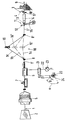
- a weft 1 is drawn off from a stationary weft supply spool 2, which is arranged outside the loom 4 of the loom formed by warp threads 3.
- the weft thread 1 running out of the supply spool 2 is wound onto a drum store 5, drawn off overhead in the axial direction and guided through a thread brake 7, a compressed air nozzle 6 and a deflection device 10 into a weft insertion device 11.
- the deflection device 10 contains two fixed guide eyelets 8, 8 'and a deflection element 16 arranged movably between them and adjustable transversely to the weft insertion direction , shown a projectile 14 provided with a weft thread clip 13.
- the projectile 14 can be fired into the shed 4 by a striking lever 15, the weft thread 1 being inserted.
- the projectile 14 is braked and pushed back into a thread release position by a defined amount.
- the weft thread 1 is deflected by the deflecting element 16 from a substantially stretched thread path 1a shown in dash-dotted lines into a loop path-like thread path 1b also shown in dash-dotted lines, so that the weft thread 1 is held taut in the shed 4. Then the weft thread 1 is knocked on in a known manner by a weaving leaf (not shown) in the tip of the shed 4 on the fabric 18 formed there and cut off by a pair of scissors 17 on the weft side.
- the end of the weft thread 1 that remains outside the shed 4 is then, as is also known, returned by the thread clamp 12 from the area of the scissors 17 into the position shown and for a subsequent weaving cycle to be transferred to another Projectile 14 ready.
- the weft thread 1 is further deflected by the deflecting element 16 out of the thread path 1b into the angled thread path 1c shown with solid lines and is kept tensioned accordingly.
- the weaving cycles can each be determined in a known manner by one revolution of a control shaft 20 of the weaving machine, from which the drives and control functions of all units of the weaving machine are derived.
- the compressed air nozzle 6 is connected via a control valve 21, which can be triggered like a trigger, to a compressed air supply line 22, which is provided with a pressure gauge 23 and is connected to a compressed air source, not shown.
- the control valve 21 can be adjusted in any manner, as shown via an electromagnetic actuating device, depending on the respective angular position of the control shaft 20 between a blocking position shown which blocks the compressed air supply to the compressed air nozzle 6 and a flow position which releases the compressed air supply.
- the control valve 21 is held in the blocking position for most of the weaving cycle and can only be adjusted to the flow position by means of a switching segment 24 indicated in the drawing, during a precisely definable fraction of the weaving cycle, which corresponds to a partial rotation of the control shaft 20 by an angle of rotation ⁇ .
- the switching segment 24, which extends over an angle of rotation ⁇ approximately 90 °, corresponds to an initial phase of the weft insertion process, in which the projectile 14 is shot into the shed 4 and which comprises at least part of the time period in which the deflection element 16 is out the deflected thread web 1c is returned against the stretched thread web 1a.
- the compressed air nozzle 6 is supplied only during this defined initial phase by means of a relatively high pressure, for example approximately 2 to 3 bar Compressed air is applied so that the section 1 'of the weft thread 1 located upstream of the guide eyelet 8 is additionally accelerated during the return movement of the deflecting element 16 into the position 16' shown in broken lines by a strong compressed air blast in the weft insertion direction according to arrow 9. This prevents the weft thread 1 from being impermissibly stressed by a "stretching stroke" when the thread path 1c is stretched out.
- a relatively high pressure for example approximately 2 to 3 bar Compressed air is applied so that the section 1 'of the weft thread 1 located upstream of the guide eyelet 8 is additionally accelerated during the return movement of the deflecting element 16 into the position 16' shown in broken lines by a strong compressed air blast in the weft insertion direction according to arrow 9.
- the start and duration of the time period provided for the application of the compressed air nozzle 6 are variable within an adjustment range given by the design and the performance data of the weaving machine and can take place within the weaving cycle, e.g. according to the yarn material to be processed, adapted to the respective conditions.
- the compressed air supply to the compressed air nozzle 6 can be controlled so that the maximum air pressure provided for the additional acceleration of the weft thread 1 essentially only in the second half of that for the return of the deflecting element 16 or Weft thread 1 is effective against the thread path 1a certain period. Accordingly, it can be achieved that the section 1 ′ of the weft thread 1 located upstream of the guide eyelet 8 is accelerated from the rest position to the desired speed only shortly before the stretched position of the weft thread 1 is reached, and thus an abrupt stress on the weft thread 1 is avoided at the crucial point in time.
- the pressure of the compressed air provided for the additional acceleration of the weft thread 1 can expediently be built up essentially during the first half of the period of time intended for the return of the weft thread 1 against the thread path 1a.
- the section 1 'of the weft thread 1 located upstream of the guide eyelet 8 can thus move from the rest position to the desired speed, regardless of the section 1' 'located downstream of the guide eyelet 8' which is already in motion due to the projectile 14 being fired be accelerated.
- the start of the compressed air supply can be varied within a period of time within a period of time before the start of the time period provided for the return of the weft thread 1 against the thread path 1a, as determined by the time the projectile 14 was fired predetermined fraction, e.g. 10% of the time period mentioned or a rotation angle ⁇ of approximately 0 to 10 ° of the control shaft 20 corresponds.
- a balanced loading of the weft thread 1 during the weft insertion process can be achieved by the compressed air supply to the compressed air nozzle 6 is controlled that the section 1 'of the weft thread 1 located upstream of the guide eyelet 8 is in each case pre-accelerated to a speed which is a predetermined fraction, for example half, of the speed of the section 1' located downstream of the guide eyelet 8 'and accelerated by the projectile 14 'corresponds to the weft thread 1.
- a second compressed air nozzle in addition to the compressed air nozzle 6 blowing in the weft insertion direction (arrow 9), a second compressed air nozzle, not shown, which blows in the opposite direction can also be provided, which, in a known manner, for braking the weft thread 1 during an end phase of the weft insertion process, for example Compressed air can be applied via a correspondingly controllable control valve.
- the thread brake 7 can optionally be omitted or, e.g. for the processing of fine weft yarns, only as an organ for holding and releasing the weft thread 1 and controlled in certain angular sections of the weaving cycle.
- the compressed air nozzle 6 and the brake nozzle can also be arranged in a combined, common unit, which can be controlled separately from one another.
- thread brake 7 between the compressed air nozzle 6 and the deflection device 10 is arranged.
- the invention can also be used for weaving machines with another weft insertion element, for example a rapier belt.
Landscapes
- Engineering & Computer Science (AREA)
- Textile Engineering (AREA)
- Looms (AREA)
Claims (8)
- Procédé pour influer sur le mouvement d'un fil de trame (1) tiré d'une bobine de réserve (2) vers le dispositif d'insertion de trame (11) d'une machine à tisser, en particulier d'une machine à tisser à projectile, ledit fil de trame (1) étant transmis, à chaque cycle de tissage, à un organe d'insertion de trame (14) traversant la foule (4) pour insérer la trame, le fil de trame (1) étant soumis à une accélération supplémentaire par une buse à air comprimé (6) implantée entre la bobine de réserve (2) et le dispositif d'insertion de trame (11), étant tiré en arrière d'une longueur prédéterminée après l'insertion de trame par un élément de déviation (16) déplaçable transversalement à la direction d'insertion de la trame (flèche 9) et, à cet endroit, étant amené d'une nappe de fils sensiblement tendue (1a) vers une nappe de fils coudée en forme de boucle (1c) et étant ramené de celle-ci dans la nappe de fils tendue (1a) lors de l'insertion de trame suivante, caractérisé en ce que la buse à air comprimé (6) destinée à réaliser l'accélération supplémentaire du fil de trame (1) est alimentée en air comprimé au cours d'une fraction prédéterminée de chaque cycle de tissage correspondant, durant l'opération d'insertion de trame, à une phase initiale comprenant au moins une partie d'un laps de temps destiné au retour du fil de trame (1) de la nappe de fils coudée (1c) vers la nappe de fils sensiblement tendue (1a), et en ce que, à l'issue de ce retour du fil de trame (1), l'alimentation en air comprimé de la buse à air comprimé (6) est interrompue durant la partie restante du cycle de tissage.
- Procédé selon la revendication 1, caractérisé en ce que l'alimentation en air comprimé de la buse à air comprimé (6) est commandée de façon que la pression maximale d'air comprimé prévue pour l'accélération supplémentaire du fil de trame (1) agisse sensiblement dans la seconde moitié du laps de temps destiné au retour du fil de trame (1) vers la nappe de fils tendue (1a).
- Procédé selon la revendication 1 ou 2, caractérisé en ce que la pression d'air comprimé prévue pour l'accélération supplémentaire du fil de trame (1) est produite sensiblement au cours de la première moitié du laps de temps destiné au retour du fil de trame (1) vers la nappe de fils tendue (1a).
- Procédé selon l'une des revendications précédentes, caractérisé en ce que le début de l'alimentation en air comprimé de la buse à air comprimé (6) se situe chronologiquement avant le début du laps de temps destiné au retour du fil de trame (1) vers la nappe de fils tendue (1a), au cours d'un intervalle de temps correspondant à une fraction prédéterminée, par exemple à 10 %, dudit laps de temps.
- Procédé selon l'une des revendications précédentes, caractérisé en ce que l'alimentation en air comprimé de la buse à air comprimé (6) est commandée de façon qu'une portion (1') du fil de trame (1) placée en amont de l'élément de déviation (16) soit préaccélérée à une vitesse correspondant à une fraction prédéterminée, par exemple à la moitié, de la vitesse d'une portion (1") du fil de trame (1) accélérée par l'organe d'insertion de trame (14) et placée en aval de l'élément de déviation (16).
- Procédé selon la revendication 5, caractérisé en ce que l'alimentation en air comprimé de la buse à air comprimé (6) est commandée de façon que la vitesse de l'air comprimé prévue pour préaccélérer la portion de fil (1') placée en amont de l'élément de déviation (16) est atteinte sensiblement au cours du premier tiers du laps de temps prévu pour le retour du fil de trame (1) vers la nappe de fils tendue (1a).
- Machine à tisser pour réaliser le procédé selon l'une des revendications précédentes, caractérisée en ce que la buse à air comprimé (6) est reliée à une valve de commande (21) qui est destinée à n'être actionnée que brièvement au cours de la fraction prédéterminée du cycle de tissage et qui, au début de l'opération d'insertion de trame, peut être amenée d'une position d'arrêt interdisant l'alimentation en air comprimé à une position de passage autorisant l'alimentation en air comprimé de la buse à air comprimé et, après la phase initiale de l'opération d'insertion de trame définie par le retour de l'élément de déviation (16) vers la nappe de fils tendue (1a), peut être amenée en position d'arrêt, et qui conserve cette position d'arrêt jusqu'à l'insertion de trame suivante.
- Machine à tisser selon la revendication 7, caractérisée en ce que, lors de chaque cycle de tissage défini par une rotation d'un arbre de commande (20), la fraction de ce cycle de tissage prédéterminée pour l'actionnement de la buse à air comprimé (6) correspond à une rotation partielle de l'arbre de commande (20) selon un angle de rotation (α) d'environ 60° à 120°, par exemple de 90°.
Priority Applications (3)
| Application Number | Priority Date | Filing Date | Title |
|---|---|---|---|
| EP93810220A EP0617153B1 (fr) | 1993-03-26 | 1993-03-26 | Procédé pour influencer le mouvement d'un fil de trame tiré d'une bobine de réserve vers le dispositif d'insertion de trame d'un métier à tisser et métier à tisser pour l'exécution de ce procédé |
| DE59304128T DE59304128D1 (de) | 1993-03-26 | 1993-03-26 | Verfahren zum Beeinflussen der Bewegung eines von einer Vorratsspule abzuziehenden, gegen eine Schusseintragseinrichtung einer Webmaschine verlaufenden Schussfadens und Webmaschine zur Durchführung des Verfahrens |
| US08/184,317 US5423355A (en) | 1993-03-26 | 1994-01-21 | Method and apparatus for limiting stresses in weft yarn advancing towards a weft insertion mechanism |
Applications Claiming Priority (1)
| Application Number | Priority Date | Filing Date | Title |
|---|---|---|---|
| EP93810220A EP0617153B1 (fr) | 1993-03-26 | 1993-03-26 | Procédé pour influencer le mouvement d'un fil de trame tiré d'une bobine de réserve vers le dispositif d'insertion de trame d'un métier à tisser et métier à tisser pour l'exécution de ce procédé |
Publications (2)
| Publication Number | Publication Date |
|---|---|
| EP0617153A1 EP0617153A1 (fr) | 1994-09-28 |
| EP0617153B1 true EP0617153B1 (fr) | 1996-10-09 |
Family
ID=8214941
Family Applications (1)
| Application Number | Title | Priority Date | Filing Date |
|---|---|---|---|
| EP93810220A Expired - Lifetime EP0617153B1 (fr) | 1993-03-26 | 1993-03-26 | Procédé pour influencer le mouvement d'un fil de trame tiré d'une bobine de réserve vers le dispositif d'insertion de trame d'un métier à tisser et métier à tisser pour l'exécution de ce procédé |
Country Status (3)
| Country | Link |
|---|---|
| US (1) | US5423355A (fr) |
| EP (1) | EP0617153B1 (fr) |
| DE (1) | DE59304128D1 (fr) |
Families Citing this family (7)
| Publication number | Priority date | Publication date | Assignee | Title |
|---|---|---|---|---|
| DE19611320C2 (de) * | 1996-03-22 | 1999-05-20 | Dornier Gmbh Lindauer | Verfahren und Vorrichtung zum pneumatischen Unterstützen des Eintragens und Spannens eines Schußfadens in Webmaschinen |
| EP0919654B1 (fr) * | 1997-11-28 | 2002-07-31 | Sulzer Textil Ag | Procédé et dispositif pour l'insertion de trame dans les métiers à tisser à ouverture des fils en série |
| DE102010044127B3 (de) * | 2010-11-18 | 2011-12-29 | Lindauer Dornier Gesellschaft Mit Beschränkter Haftung | Greiferkopf zum Eintrag von Schussfäden an einer Greiferwebmaschine sowie eine Greiferwebmaschine mit einem derartigen Greiferkopf |
| JP5229351B2 (ja) * | 2011-05-06 | 2013-07-03 | 株式会社豊田自動織機 | 織機における緯糸貯留装置 |
| JP5273205B2 (ja) * | 2011-05-27 | 2013-08-28 | 株式会社豊田自動織機 | 織機における緯糸貯留装置 |
| DE102012208158B3 (de) * | 2012-05-15 | 2013-09-05 | Lindauer Dornier Gmbh | Luftdüsenwebmaschine mit einer Vorrichtung zur Druckluftversorgung |
| SE1650986A1 (en) * | 2016-07-06 | 2018-01-07 | Iro Ab | Weft yarn feeding arrangement with motor drive |
Family Cites Families (5)
| Publication number | Priority date | Publication date | Assignee | Title |
|---|---|---|---|---|
| CH654601A5 (de) * | 1982-04-07 | 1986-02-28 | Sulzer Ag | Schussfadenspannvorrichtung fuer webmaschinen, insbesondere greiferpojektil-webmaschinen. |
| EP0155432A1 (fr) * | 1984-03-23 | 1985-09-25 | GebràDer Sulzer Aktiengesellschaft | Machine à tisser |
| DE3564596D1 (en) * | 1985-01-28 | 1988-09-29 | Sulzer Ag | Arrangement for the insertion of at least one weft thread into looms |
| EP0389410A1 (fr) * | 1989-03-17 | 1990-09-26 | Sulzer RàTi Ag | Dispositif d'enfilage de fil de trame pour métier à tisser |
| US5199468A (en) * | 1990-06-21 | 1993-04-06 | Sulzer Brothers Limited | Weft yarn clearing device |
-
1993
- 1993-03-26 EP EP93810220A patent/EP0617153B1/fr not_active Expired - Lifetime
- 1993-03-26 DE DE59304128T patent/DE59304128D1/de not_active Expired - Fee Related
-
1994
- 1994-01-21 US US08/184,317 patent/US5423355A/en not_active Expired - Fee Related
Also Published As
| Publication number | Publication date |
|---|---|
| EP0617153A1 (fr) | 1994-09-28 |
| US5423355A (en) | 1995-06-13 |
| DE59304128D1 (de) | 1996-11-14 |
Similar Documents
| Publication | Publication Date | Title |
|---|---|---|
| EP0605531B1 (fr) | Metier mecanique et frein d'insertion pour metiers mecaniques | |
| DE69107536T2 (de) | Vorrichtung zur Spannungsregulierung und Rückziehen von Schussgarn in Webmaschinen. | |
| EP0475892A1 (fr) | Frein de fil pour métiers à tisser | |
| DE10244694B4 (de) | Verfahren zum Halten eines Schussfadens im Bereich einer Hauptdüse einer Düsenwebmaschine sowie Düsenwebmaschine zur Durchführung des Verfahrens | |
| EP1440193B1 (fr) | Systeme de traitement de fils | |
| EP0155432A1 (fr) | Machine à tisser | |
| EP0617153B1 (fr) | Procédé pour influencer le mouvement d'un fil de trame tiré d'une bobine de réserve vers le dispositif d'insertion de trame d'un métier à tisser et métier à tisser pour l'exécution de ce procédé | |
| DE9420562U1 (de) | Bandwebmaschine | |
| DE19611320C2 (de) | Verfahren und Vorrichtung zum pneumatischen Unterstützen des Eintragens und Spannens eines Schußfadens in Webmaschinen | |
| EP1038061B1 (fr) | Dispositif accumulateur | |
| EP0963470B1 (fr) | Systeme d'alimentation dosee | |
| DE60200740T2 (de) | Vorrichtung zum Versanften des Abwickelns von Garnwindungen vom Zylinder zur Bildung des Schussfadenvorrats in Schussfadenliefergeräten für Düsenwebmaschinen | |
| EP0445489A1 (fr) | Dispositif de mesure du fil de trame d'un métier à tisser | |
| DE10213639C1 (de) | Verfahren und Vorrichtung zum Zubringen eines geklemmten Schussfadens zu einem Bringergreifer einer Webmaschine | |
| EP0022226B1 (fr) | Métier à tisser à buses | |
| EP1576219B1 (fr) | Dispositif et procede d'etirage | |
| EP0155431A1 (fr) | Procédé d'insertion de fil de trame pour un métier à tisser et métier à tisser pour réaliser ce procédé | |
| DE2752094A1 (de) | Anordnung zum eintragen von schussfaeden | |
| DE4008864A1 (de) | Verfahren zur steuerung des schusseintrages in luftwebmaschinen und vorrichtung zur beeinflussung des schussfadens | |
| DE3345627A1 (de) | Vorrichtung zum eintragen eines schussfadens in das fach einer webmaschine | |
| EP1606442B1 (fr) | Metier mecanique, notamment machine a tisser des rubans | |
| EP0390730A1 (fr) | Fournisseur de fil, tuyère pour un tel fournisseur ainsi que leur application | |
| DE102023205630B3 (de) | Verfahren zur bildung einer schlaufenförmigen webkante an einer greiferwebmaschine und greiferwebmaschine | |
| CH508074A (de) | Webmaschine | |
| WO2005064059A1 (fr) | Dispositif pour recevoir une section d'un fil de trame |
Legal Events
| Date | Code | Title | Description |
|---|---|---|---|
| PUAI | Public reference made under article 153(3) epc to a published international application that has entered the european phase |
Free format text: ORIGINAL CODE: 0009012 |
|
| AK | Designated contracting states |
Kind code of ref document: A1 Designated state(s): DE |
|
| 17P | Request for examination filed |
Effective date: 19950301 |
|
| GRAG | Despatch of communication of intention to grant |
Free format text: ORIGINAL CODE: EPIDOS AGRA |
|
| 17Q | First examination report despatched |
Effective date: 19951219 |
|
| GRAH | Despatch of communication of intention to grant a patent |
Free format text: ORIGINAL CODE: EPIDOS IGRA |
|
| RBV | Designated contracting states (corrected) |
Designated state(s): DE |
|
| GRAH | Despatch of communication of intention to grant a patent |
Free format text: ORIGINAL CODE: EPIDOS IGRA |
|
| GRAA | (expected) grant |
Free format text: ORIGINAL CODE: 0009210 |
|
| AK | Designated contracting states |
Kind code of ref document: B1 Designated state(s): DE |
|
| REF | Corresponds to: |
Ref document number: 59304128 Country of ref document: DE Date of ref document: 19961114 |
|
| PLBE | No opposition filed within time limit |
Free format text: ORIGINAL CODE: 0009261 |
|
| STAA | Information on the status of an ep patent application or granted ep patent |
Free format text: STATUS: NO OPPOSITION FILED WITHIN TIME LIMIT |
|
| 26N | No opposition filed | ||
| PGFP | Annual fee paid to national office [announced via postgrant information from national office to epo] |
Ref country code: DE Payment date: 20040305 Year of fee payment: 12 |
|
| PG25 | Lapsed in a contracting state [announced via postgrant information from national office to epo] |
Ref country code: DE Free format text: LAPSE BECAUSE OF NON-PAYMENT OF DUE FEES Effective date: 20051001 |