EP0614633B1 - Verstellbare Rückenlehne für einen Stuhl - Google Patents
Verstellbare Rückenlehne für einen Stuhl Download PDFInfo
- Publication number
- EP0614633B1 EP0614633B1 EP94300577A EP94300577A EP0614633B1 EP 0614633 B1 EP0614633 B1 EP 0614633B1 EP 94300577 A EP94300577 A EP 94300577A EP 94300577 A EP94300577 A EP 94300577A EP 0614633 B1 EP0614633 B1 EP 0614633B1
- Authority
- EP
- European Patent Office
- Prior art keywords
- housing
- backrest
- stem
- rack
- chair
- Prior art date
- Legal status (The legal status is an assumption and is not a legal conclusion. Google has not performed a legal analysis and makes no representation as to the accuracy of the status listed.)
- Expired - Lifetime
Links
Images


Classifications
-
- A—HUMAN NECESSITIES
- A47—FURNITURE; DOMESTIC ARTICLES OR APPLIANCES; COFFEE MILLS; SPICE MILLS; SUCTION CLEANERS IN GENERAL
- A47C—CHAIRS; SOFAS; BEDS
- A47C7/00—Parts, details, or accessories of chairs or stools
- A47C7/36—Support for the head or the back
- A47C7/40—Support for the head or the back for the back
-
- A—HUMAN NECESSITIES
- A47—FURNITURE; DOMESTIC ARTICLES OR APPLIANCES; COFFEE MILLS; SPICE MILLS; SUCTION CLEANERS IN GENERAL
- A47C—CHAIRS; SOFAS; BEDS
- A47C1/00—Chairs adapted for special purposes
- A47C1/02—Reclining or easy chairs
- A47C1/022—Reclining or easy chairs having independently-adjustable supporting parts
- A47C1/023—Reclining or easy chairs having independently-adjustable supporting parts the parts being horizontally-adjustable seats ; Expandable seats or the like, e.g. seats with horizontally adjustable parts
-
- A—HUMAN NECESSITIES
- A47—FURNITURE; DOMESTIC ARTICLES OR APPLIANCES; COFFEE MILLS; SPICE MILLS; SUCTION CLEANERS IN GENERAL
- A47C—CHAIRS; SOFAS; BEDS
- A47C1/00—Chairs adapted for special purposes
- A47C1/02—Reclining or easy chairs
- A47C1/022—Reclining or easy chairs having independently-adjustable supporting parts
- A47C1/024—Reclining or easy chairs having independently-adjustable supporting parts the parts, being the back-rest, or the back-rest and seat unit, having adjustable and lockable inclination
- A47C1/026—Reclining or easy chairs having independently-adjustable supporting parts the parts, being the back-rest, or the back-rest and seat unit, having adjustable and lockable inclination by means of peg-and-notch or pawl-and-ratchet mechanism
-
- A—HUMAN NECESSITIES
- A47—FURNITURE; DOMESTIC ARTICLES OR APPLIANCES; COFFEE MILLS; SPICE MILLS; SUCTION CLEANERS IN GENERAL
- A47C—CHAIRS; SOFAS; BEDS
- A47C7/00—Parts, details, or accessories of chairs or stools
- A47C7/36—Support for the head or the back
- A47C7/40—Support for the head or the back for the back
- A47C7/402—Support for the head or the back for the back adjustable in height
Definitions
- the present invention relates generally to office chairs, and more particularly, to an apparatus for adjusting the position of a backrest relative to the seat of an office chair.
- Many office chairs have backrests which can be adjusted in height or angle relative to a seat. It is also desirable to adjust both the height and the angle of a backrest so that the position of the backrest corresponds to the natural position of a user's back when the user is in a desired forward or reclined position. When a user reclines or leans forward, the torso generally pivots about an axis through the hip joints of the user. Thus, it is desirable to provide a backrest with a path of movement corresponding to the pivotal movement of the user's back.
- the patent to Street discloses a similar mechanism including an integral portion of a seat frame provided with inner and outer cylindrically convex regions complementary to concave faces of a block.
- a hand piece is rotated to allow disengagement of the complementary serrated parts and permit angular movement together of the block and stem of a backrest in relation to a seat frame.
- U.S. Patent No. 910,357 to Case discloses a seat frame provided with a back bracket which is formed with a T-shaped slide channel that extends longitudinally backward and upward along the arc of a circle.
- the lower end of a backrest shank is curved downward and forward to fit and slide longitudinally in the channel of the back bracket.
- a spring-latch is provided in the shank which is adapted to normally enter and operate in a small longitudinal groove in the channel.
- a wedge block is located in a recess in one side of the concave face of the shank. The block is adapted to be forced toward the adjoining wall of the slide channel by a screw having a handle.
- US Patent No. 2,307,6321 to Spotifyon discloses an adjustable chair. Front and rear legs of the chair are joined together by longitudinal members and a seat frame with arm rests is secured upon the longitudinal members by bolts.
- a back frame includes front members which are connected at their lower ends to the respective arm rests by means of hinges so that the back frame may be swung downward and upward. The hinges pivot about a point below the surface of the cushioned and spring supported seating surface.
- the back frame is secured in any of its adjusted positions by means of a pair of segmental elements in the form of racks concentric to the axis of the hinges and a pair of dètents for engaging the racks.
- the back is swung downward through pressure exerted thereon by the occupant and automatically swings upward due to the action of coil springs arranged in the seat frame when relieved of such pressure.
- the invention is directed to a chair, and more particularly, to an apparatus for adjusting the position of a backrest relative to a seat.
- an apparatus for adjusting the position of a backrest relative to a chair seat comprising: said backrest including an elongated stem having a curved lower portion that curves along an arc having a center defined by a horizontal line approximately through the hip joints of a user sitting in the chair seat; a spring operably engaging the stem to bias said stem in an upward direction: a housing adapted to slidably receive the curved portion of the stem and guide the spring; a latch mechanism adapted to lock the lower portion of the stem in a plurality of fixed desired positions within the housing, said latch mechanism, comprising a rack on the lower portion of the stem and a pawl adapted to operably engage the rack; an actuator member adapted to move the latch mechanism between an engaged and disengaged position; and whereby disengagement of the latch mechanism allows the backrest stem to move in a curvilinear path to a desired height and corresponding angular position for the backrest and whereupon reengagement of the latch mechanism locks the back
- the rack has substantially the same curvature as the curved portion of the backrest and a plurality of teeth extending outwardly therefrom.
- the housing preferably has an aperture for slidably receiving the curved portion of the stem and a cavity therein for slidably receiving the rack.
- the pawl is preferably actuated by a lever with one end accessible from outside side of the housing.
- the housing is adjustably attached to a seat support member.
- the housing is movable between a forward position adjacent the seat support member and a rearward position spaced apart from the seat support member, thus allowing further adjustment of the backrest.
- Embodiments of the present invention provide significant advantages over other adjustable backrests.
- the curved lower portion of the backrest stem allows the position of the backrest to correspond with the natural posture of the back of a user in various reclined positions.
- the path of the backrest is defined by an arc with its center at the hip joints of a user sitting in the seat.
- the housing can be made as a sturdy guide for the backrest with an attractive encasement for concealing the backrest stem and latch mechanism.
- the stem and the rack slide easily in the housing, and in combination with the spring provide for easy adjustment of the backrest.
- positioning the lever on the side of the housing provides a convenient and easily accessible means for actuating the pawl to allow the backrest to be adjusted while a user sits in the seat.
- FIGURE 1 is a perspective view of a chair with a backrest adjustment mechanism embodying the present invention.
- FIGURE 2 is a side view of the chair showing the backrest in a raised and forward position and a lowered rearward position.
- FIGURE 3 is a side view of the chair, partially in cross-section, showing the backrest in a raised and forward position.
- FIGURE 4 is a side view of the chair, partially in cross-section, showing the backrest in a lowered and rearward position.
- FIGURE 5 is a cross-sectional view of the backrest adjustment mechanism taken along the line 5-5 in Figure 4.
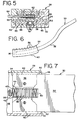
- FIGURE 6 is a side view of a backrest stem and a rack.
- FIGURE 7 is a top view of the stem and rack in Figure 6.
- FIGURE 8 is a side view of a tilt housing and a backrest support stem.
- FIGURE 9 is top view of the tilt housing in Figure 8 shown with a portion of a top wall removed for clarity.
- FIG. 1 shows a chair indicated generally at 10.
- the chair 10 includes a base structure 12 having a wheeled star-like base 14 and a vertically adjustable pedestal 16 extending upwardly therefrom.
- a stationary housing (not shown) is mounted to the pedestal 16, and a tilt housing 18 is mounted to the stationary housing for pivotal movement about a horizontal axis.
- the pivot axis of the tilt housing 18 can intersect the vertical axis of the pedestal 16, and a seat 20 is attached to the tilt housing 18.
- a spring (not shown) is provided for biasing the tilt housing 18 in an upward direction.
- a tilt control mechanism of this type is sold by Herman Miller, Inc. as P/N 238714 for use with its Ergon® line of office chairs.
- a pair of armrests (not shown) can extend upwardly from the tilt housing 18, and a backrest 24 is attached to the tilt housing by a backrest adjustment mechanism 26.
- the backrest adjustment mechanism can be incorporated into any type of tilting chair or even a non-tilting chair.
- the tilt housing can be rigidly mounted to the pedestal and the seat can be pivotally attached to a front end of the housing to provide a "knee-tilt" chair.
- a four-bar linkage or the like can also be employed to pivotally connect the seat to a stationary housing.
- the backrest adjustment mechanism 26 includes a housing 28 attached to the tilt housing 18 in a manner which will be described in more detail below.
- the backrest 24 includes an elongated, rectangular stem 30 having a curved lower portion 32 which is slidably received by the housing 28.
- the lower portion 32 preferably curves along an arc having a center defined by a horizontal axis through the hip joints of a user sitting in the seat 20. This allows the position of the backrest 24 to correspond to the natural position of a user's back when the user is in a desired reclined position.
- the backrest 24 can also tilt forward past a vertical plane to provide a comfortable support for a user leaning forward in a task-intensive work environment.
- a rack 34 is rigidly attached to or integral with the lower end of the stem 30 and has the same curvature as the curved portion 32 of the backrest stem 30.
- the rack 34 includes a top plate 36 having a plurality of teeth 38 extending outwardly from the longitudinal center thereof. Preferably, the teeth 38 extend upwardly at an angle toward the top of the rack 34.
- the rack 34 also has side flanges 40 extending downwardly from the top plate 36, and spaced apart ribs 42 extending downwardly from the longitudinal center of the top plate 36. As best shown in Figure 7, the ribs 42 fit within a longitudinal slot 44 formed in a lower end of the stem 30.
- the ribs 42 and slot 44 are preferably the same length as the top plate 36 and flanges 40 of the rack 34.
- the housing 28 has a cavity 46 configured to slidably receive the rack 34.
- the cavity 46 is defined by a bottom surface 48 having the same curvature as the rack 34, and side walls 50 which bear against the flanges 40 of the slidable rack 34.
- a top wall 52 and bottom wall 54 of the cavity 46 act as an upper and lower stop against which the rack 34 abuts.
- Further guidance of the backrest 24 is provided by a bushing 56 which is configured to slidably receive the curved portion 32 of the backrest stem.
- a spring 58 is preferably provided to bias the backrest 24 in an upward direction.
- the spring 58 is positioned between the ribs 42 and curved top plate 36 of the rack and the bottom surface 48 of the housing cavity 46.
- One end of the spring 58 bears against the bottom wall 54 of the cavity 46, and another end of the spring 58 bears against an inner wall 60 of the slot 44 in the stem 30. Because a substantial portion of the spring 58 is constrained between the curved top plate 36 of the rack 34 and the curved bottom surface 48 of the cavity 46, the axis of the spring 58 conforms to the curvature of these surfaces. As shown in Figure 3, the spring 58 retains this curvature even when a portion is not guided by the rack 34.
- a pawl 62 is positioned within the housing cavity 46 above the teeth 38 of the rack 34.
- the pawl 62 is rotatably attached to the housing 28 by a rod 64, and a handle 66 extends perpendicularly from an end of the rod 64 for actuating the pawl.
- the pawl is biased toward the rack.
- the pawl 62 is rotatable between a disengaged and engaged position with the teeth 38 of the rack 34 to lock the backrest 24 in a desired position.
- a user rotates the rod 64 in one direction by the handle 66 to disengage the pawl 62 from the rack 34.
- the user moves the backrest 24 and stem 30 in a curvilinear direction to a desired height and corresponding angular position.
- the user rotates the rod 64 in an opposite direction to reengage the pawl 62 with the rack 34 to lock the backrest 24 in the desired position.
- the housing 28 is movable in a linear direction between a forward position adjacent the tilt housing 18 ( Figure 3) and a rearward position spaced apart from the tilt housing 18 (Figure 4).
- the housing 28 is mounted to the tilt housing 18 by a support bracket 68 which extends outwardly from the housing 28 and into a slot 70 formed the tilt housing 18.
- a latch mechanism 72 is provided for locking the housing 28 and backrest 24 in a desired rearward position.
- the latch mechanism 72 includes a rack 74 and a pawl 76 positioned within the tilt housing 18.
- the rack 74 is mounted to the support bracket 68 and also fits into the slot 70.
- the rack 74 also has a plurality of teeth 78 extending outwardly from a side edge thereof.
- the pawl 76 is rotatably attached to the tilt housing 18 by a pivot pin 80 which extends vertically upward from a bottom wall 82 of the tilt housing 18.
- the pawl 76 has a pair of teeth 81 for engagement with two of the rack teeth 78.
- an actuator member (not shown) is rotated in one direction to disengage the pawl 76 from the teeth 78 of the rack 74, the backrest 24 is moved forwardly or rearwardly to a desired position, and the actuator member is rotated in an opposite direction to reengage the pawl 76 with the rack 74.
- movement of the housing 28 and backrest 24 in a forward linear direction is aided by a spring 84.
- the spring 84 has an end 86 fastened to the rack 74 and an end 88 fastened to a vertical pin 90 which is mounted to the tilt housing 18.
- the housing 28 of the adjustable backrest mechanism 26 can comprise various configurations in accordance with the present invention.
- the tilt housing 18 can be stationary and the seat 20 can tilt relative to the housing 18.
- the backrest housing 28 can also be configured as a stationary or tiltable seat support housing rather than a separate unit attached to a seat support housing.
- the seat and the backrest can be independently tiltable relative to each other.
- an apparatus for easily adjusting the backrest of a chair in a curvilinear direction and locking the backrest at a desired height and corresponding angular position. Also, the housing for the backrest adjustment mechanism is an attractive way to conceal the locking mechanism and provide guidance for the backrest stem.
Landscapes
- Health & Medical Sciences (AREA)
- Dentistry (AREA)
- General Health & Medical Sciences (AREA)
- Chairs Characterized By Structure (AREA)
- Chairs For Special Purposes, Such As Reclining Chairs (AREA)
- Chair Legs, Seat Parts, And Backrests (AREA)
Claims (18)
- Einstellvorrichtung für die Position einer Rückenlehne (24) relativ zu einem Stuhlsitz (20), welche umfaßt:daß die Rückenlehne (24) einen länglichen Schaft (30) mit einem gebogenen unteren Abschnitt (32) enthält, der längs eines Bogens verläuft mit einem Zentrum, welches durch eine annähernd durch die Hüftgelenke eines in dem Stuhlsitz sitzenden Benutzers gehende horizontale Linie definiert ist;eine wirksam an dem Schaft (30) zum Vorspannen des Schaftes in einer Richtung nach oben angreifende Feder (58);ein zur gleitenden Aufnahme des gebogenen Abschnittes (32) des Schaftes (30) und zum Führen der Feder (58) ausgelegtes Gehäuse (28);einen Riegel-Mechanismus (62, 34), der ausgelegt ist, den unteren Abschnitt (32) des Schaftes in einer Vielzahl festgelegter gewünschter Positionen innerhalb des Gehäuses (28) zu verriegeln, welcher Riegel-Mechanismus (62, 34) eine Zahnstange (34) am unteren Abschnitt des Schaftes und eine zum wirksamen Eingriff in die Zahnstange ausgelegte Klaue (64) umfaßt;ein Betätigungsteil (66), das ausgelegt ist, den Riegel-Mechanismus (62, 34) zwischen einer Eingriff- und einer Löse-Position zu bewegen; und
wobei Lösen des Riegel-Mechanismus (62, 34) eine Bewegung des Rückenlehnen-Schaftes (30) auf einem krummlinigen Weg zu einer Position mit gewünschter Höhe und entsprechender Winkelposition für die Rückenlehne (24) erlaubt, und ein darauffolgendes Wiedereingreifen des Riegel-Mechanismus (62, 34) den Rückenlehnen-Schaft (30) in dieser Position verriegelt. - Vorrichtung nach Anspruch 1, bei der das Gehäuse (28) eine Öffnung zur gleitenden Aufnahme des gebogenen Abschnittes (32) des Schaftes und einen darin befindlichen Hohlraum (46) zum Aufnehmen des gebogenen Abschnittes (32) besitzt, und bei der der Riegel-Mechanismus (62, 34) in den Gehäuse-Hohlraum eingesetzt ist.
- Vorrichtung nach Anspruch 1 oder 2, bei der die Zahnstange (34) eine größere Breite als der gebogene untere Abschnitt (32) und der Hohlraum (46) eine größere Breite als die Öffnung besitzt, wodurch die Zahnstange (34) gleitend in den Hohlraum (46) paßt und der Schaft gleitend in die Öffnung paßt, wobei die Breite der Zahnstange (34) größer als die Breite der Öffnung in dem Gehäuse (29) ist, um einen obersten Anschlag für das Einstellen der Rückenlehne zu schaffen.
- Vorrichtung nach einem der Ansprüche 1 oder 3, bei der die Zahnstange (34) eine Vielzahl von davon nach außen abstehenden Zähnen (36) besitzt, und die Klaue zum Eingriff mit den Zähnen ausgelegt ist.
- Vorrichtung nach einem der Ansprüche 3 oder 4, bei der die Zahnstange (34) im wesentlichen die gleiche Krümmung wie der gebogene untere Abschnitt (32) der Rückenlehne aufweist und das Gehäuse (28) zur gleitenden Aufnahme der Zahnstange (34) gestaltet ist.
- Vorrichtung nach Anspruch 5, bei der die Feder eine Achse aufweist und die Achse der Feder und eine untere Fläche (48) des Hohlraumes (46) im wesentlichen den gleichen Krümmungsverlauf wie der gebogene Abschnitt (32) der Rückenlehne (24) und die Zahnstange (34) aufweisen.
- Vorrichtung nach einem der vorangehenden Ansprüche, bei der die Feder (58) innerhalb des Gehäuse-Hohlraumes (46) eingesetzt ist.
- Vorrichtung nach Anspruch 7, die einen in einem unteren Ende des Schaftes (30) gebildeten Längsschlitz (44) umfaßt, wobei ein Ende der Feder (58) gegen die untere Wand (54) des Gehäuse-Hohlraumes (46) anliegt und ein anderes Ende der Feder (58) gegen eine Innenwand (60) des Längsschlitzes (44) anliegt.
- Vorrichtung nach Anspruch 8, bei der die Feder (58) wirksam an dem Schaft (30) an einer Stelle anliegt, die ausreichend weit von dem Ende des Schaftes (30) innerhalb des Gehäuse-Hohlraumes (46) entfernt ist, so daß die Feder (58) in ihrer Gesamtheit durch den Schaft (30) eingegrenzt wird, wenn die Rückenlehne (24) sich in einer abgesenkten Position befindet.
- Vorrichtung nach einem der vorangehenden Ansprüche, bei der das Betätigungsteil (66) von außerhalb des Gehäuses zugänglich ist.
- Vorrichtung nach einem der vorangehenden Ansprüche, bei der die Klaue (62) durch einen Stab (64) drehbar an dem Gehäuse (28) angebracht ist und das Betätigerteil einen außerhalb einer Seitenwand des Gehäuses (28) befindlichen Hebel (66) zum Drehen der Klaue (62) zwischen der Eingriffs- und der Löseposition mit der Zahnstange (34) umfaßt.
- Vorrichtung nach einem der vorangehenden Ansprüche, bei der das Gehäuse (28) einstellbar an einem hinteren Abschnitt eines Sitzstützteils angebracht ist, wobei das Gehäuse (28) zwischen einer vorderen, dem Sitzteil benachbarten Position und einer hinteren Position mit Abstand von dem Sitzstützteil bewegbar ist, so daß es für Vorwärts- und Rückwärts-Einstellung der Rückenlehne sorgt.
- Stuhl (10), welcher eine Rückenlehne (24), einen Stuhlsitz (20) und eine Vorrichtung zum Einstellen der Position der Rückenlehne (24) relativ zum Stuhlsitz gemäß einem der vorangehenden Ansprüche umfaßt.
- Stuhl (10), welcher umfaßt:einen Grundaufbau (12);ein an dem Grundaufbau (12) kippbar angebrachtes Sitzstützteil;eine Rückenlehne (24), die einen länglichen Schaft (30) mit einem gebogenen unteren Abschnitt (32) enthält; undein einstellbar an einem hinteren Abschnitt des Sitzstützteils angebrachtes Gehäuse (28), das zur gleitenden Aufnahme des gebogenen Abschnittes (32) des Schaftes (30) ausgelegt ist, wobei das Gehäuse (28) in einer allgemein linearen Richtung zwischen einer vorderen, dem Sitzstützteil benachbarten Position und einer hinteren Position mit Abstand von dem Sitzstützteil bewegbar ist;
wodurch die Rückenlehne (24) als eine Einheit mit dem Sitzstützteil kippen, sich in einem krummlinigen Weg zu einer gewünschten Höhe und der entsprechenden Winkelposition bewegen und nach vorne und hinten zu einer gewünschten Gesamtposition bewegen kann. - Stuhl nach Anspruch 14, bei dem das Gehäuse (28) eine Öffnung zur gleitenden Aufnahme des gebogenen Abschnittes (32) des Rückenlehnen-Schaftes, und einen darin befindlichen Hohlraum (46) zur Aufnahme des gebogenen Abschnittes (32) besitzt.
- Stuhl nach Anspruch 15, der weiter einen ersten Riegel-Mechanismus (62, 34) umfaßt, welcher innerhalb des Gehäuse-Hohlraums (46) eingesetzt und zum Eingriff mit dem Rückenlehnen-Schaft (30) zum Verriegeln der Rückenlehne (24) in einer gewünschten Position relativ zu dem Gehäuse (28) ausgelegt ist.
- Stuhl nach Anspruch 16, bei dem das Sitzstützteil ausgelegt ist zum Aufnehmen einer Lasche (68), die von dem Gehäuse (28) nach außen vorsteht, und weiter einen zweiten Riegel-Mechanismus (72) umfaßt, der innerhalb eines Hohlraums des Sitzstützteils eingesetzt ist, wobei der zweite Riegel-Mechanismus (72) zum Eingriff mit der Gehäuse-Lasche (68) ausgelegt ist, um das Gehäuse (28) in einer gewünschten Position relativ zum Sitzstützteil zu verriegeln.
- Stuhl nach einem der Ansprüche 14 bis 17, der weiter eine zum Vorspannen des Schaftes (30) in einer Richtung nach oben ausgelegte Feder (58) umfaßt.
Applications Claiming Priority (2)
| Application Number | Priority Date | Filing Date | Title |
|---|---|---|---|
| US22138 | 1993-02-25 | ||
| US08/022,138 US5511852A (en) | 1993-02-25 | 1993-02-25 | Adjustable backrest for a chair |
Publications (2)
| Publication Number | Publication Date |
|---|---|
| EP0614633A1 EP0614633A1 (de) | 1994-09-14 |
| EP0614633B1 true EP0614633B1 (de) | 1998-10-07 |
Family
ID=21808006
Family Applications (1)
| Application Number | Title | Priority Date | Filing Date |
|---|---|---|---|
| EP94300577A Expired - Lifetime EP0614633B1 (de) | 1993-02-25 | 1994-01-26 | Verstellbare Rückenlehne für einen Stuhl |
Country Status (7)
| Country | Link |
|---|---|
| US (1) | US5511852A (de) |
| EP (1) | EP0614633B1 (de) |
| JP (1) | JPH07248A (de) |
| KR (1) | KR940019265A (de) |
| CA (1) | CA2113951C (de) |
| DE (1) | DE69413735T2 (de) |
| ES (1) | ES2122160T3 (de) |
Families Citing this family (33)
| Publication number | Priority date | Publication date | Assignee | Title |
|---|---|---|---|---|
| US5765914A (en) | 1995-06-07 | 1998-06-16 | Herman Miller, Inc. | Chair with a tilt control mechanism |
| CA2201253C (en) * | 1997-03-27 | 2001-08-28 | William R. Breen | Chair control |
| US6250715B1 (en) * | 1998-01-21 | 2001-06-26 | Herman Miller, Inc. | Chair |
| US6007150A (en) | 1998-03-08 | 1999-12-28 | Milsco Manufacturing Company | Motorcycle seat with adjustable backrest |
| GB9928509D0 (en) * | 1999-12-03 | 2000-02-02 | Unit Press Limited | Improvements to chairs |
| US6334651B1 (en) | 2000-02-01 | 2002-01-01 | Schukra Geratebau Gmbh | Lumbar support adjusting mechanism |
| JP2004508891A (ja) * | 2000-09-19 | 2004-03-25 | ヨー、ハン−キール | 脊椎骨の異常整列を矯正するための椅子およびこの椅子で脊椎骨の異常整列を矯正するための方法 |
| US7249802B2 (en) * | 2002-02-13 | 2007-07-31 | Herman Miller, Inc. | Back support structure |
| DE20319457U1 (de) * | 2002-12-31 | 2004-04-22 | Metalseat S.R.L., Galliera Veneta | Sperrungsvorrichtung für eine Bürosesselstruktur mit Gelenk für die Bewegung des Sitzes und der Rückenlehne sowie dazugehörige Sesselstruktur |
| US20050006930A1 (en) * | 2003-03-26 | 2005-01-13 | Graco Children's Products Inc. | High chair |
| US20050017561A1 (en) * | 2003-07-21 | 2005-01-27 | Burmeister Richard F. | Seat, seat recliner mechanism, and seat recliner system |
| US20060103221A1 (en) * | 2004-10-08 | 2006-05-18 | Ronald Kleist | Ergonomic chair |
| DE102004050853A1 (de) * | 2004-10-18 | 2006-04-20 | Interstuhl Büromöbel GmbH & Co. KG | Stuhl |
| US7264312B1 (en) * | 2006-05-17 | 2007-09-04 | Chih Chiang Wang | Backrest adjusting mechanism |
| US8616641B2 (en) | 2006-10-04 | 2013-12-31 | Access Enterprise, Llc | Therapeutic back support and stabilization |
| US10842280B2 (en) | 2006-10-04 | 2020-11-24 | Access Enterprise, Llc | Therapeutic back support and stabilization |
| US20080084101A1 (en) * | 2006-10-04 | 2008-04-10 | Mark Powicki | Forward-biased postural chair |
| CN102772053A (zh) | 2007-01-29 | 2012-11-14 | 赫尔曼米勒有限公司 | 座位结构及其使用方法 |
| KR100791454B1 (ko) * | 2007-06-22 | 2008-01-03 | 주식회사 대하정공 | 의자 어셈블리 |
| KR100771416B1 (ko) * | 2007-06-25 | 2007-10-30 | 주식회사 대하정공 | 의자 어셈블리 |
| US20110095588A1 (en) * | 2008-08-19 | 2011-04-28 | Jen Li-Wen | Two-Stage Adjusting Member for Adjusting Slope of Seat Back |
| US7708344B1 (en) * | 2008-10-31 | 2010-05-04 | Midmark Corporation | Patient chair with locking assembly |
| US7802847B2 (en) * | 2008-12-16 | 2010-09-28 | Kuo-Ching Chou | Angle-adjusting structure for backrest of chair |
| US8251449B2 (en) * | 2010-04-26 | 2012-08-28 | Yao-Chuan Wu | Multi-section angle adjusting structure for a chair back |
| US8864230B2 (en) * | 2010-06-15 | 2014-10-21 | Betty A. Augustat | Ergometric chair apparatus |
| ITTO20110375A1 (it) * | 2011-04-29 | 2012-10-30 | Pro Cord Spa | Sedia con schienale oscillante |
| US11304528B2 (en) | 2012-09-20 | 2022-04-19 | Steelcase Inc. | Chair assembly with upholstery covering |
| USD697726S1 (en) | 2012-09-20 | 2014-01-21 | Steelcase Inc. | Chair |
| CN104433402B (zh) * | 2014-11-28 | 2017-08-15 | 叶佳 | 一种折叠坐具 |
| US9578971B2 (en) * | 2015-08-02 | 2017-02-28 | Dongguan Kentec Office Seating Co., Ltd. | Armrest interval adjustment structure for a chair |
| USD889152S1 (en) * | 2018-06-05 | 2020-07-07 | Herman Miller, Inc. | Chair |
| CN113729426A (zh) * | 2021-05-27 | 2021-12-03 | 广东联友办公家具有限公司 | 一种座椅底盘及座椅 |
| US11730269B1 (en) * | 2022-03-10 | 2023-08-22 | Gary Rosebrook | Posture control chair |
Family Cites Families (31)
| Publication number | Priority date | Publication date | Assignee | Title |
|---|---|---|---|---|
| GB190005254A (en) * | 1900-03-20 | 1900-04-21 | Eduard Wever | Body Support for Cycle Saddles. |
| US910357A (en) * | 1906-06-25 | 1909-01-19 | Harvard Company | Dental chair. |
| GB191423621A (en) * | 1914-12-05 | 1915-07-29 | Jethro Foot | Improvements in and connected with Reclining Chairs. |
| FR631285A (fr) * | 1927-03-08 | 1927-12-17 | Siège amovible pour motocyclette | |
| AT124229B (de) * | 1930-04-28 | 1931-08-25 | Sembustowerk Holzindustrie Und | Sessel. |
| GB381086A (en) * | 1932-03-09 | 1932-09-29 | Tan Sad Chair Co 1931 Ltd | An improved backrest or back support for a seat or the like |
| US2313023A (en) * | 1937-09-07 | 1943-03-02 | Ruegger Andre | Tiltable seat |
| US2272980A (en) * | 1939-02-11 | 1942-02-10 | Mclellan | Chair construction |
| US2271925A (en) * | 1939-06-12 | 1942-02-03 | Harry F Niles | Chair |
| US2307621A (en) * | 1940-05-21 | 1943-01-05 | John M Dorton | Adjustable chair |
| US2369580A (en) * | 1943-06-28 | 1945-02-13 | Edward L Koenig | Chair |
| GB793890A (en) * | 1956-02-23 | 1958-04-23 | Tan Sad Chair Co 1931 Ltd | Adjustable clamping means for the back rest of a chair or seat |
| US3232574A (en) * | 1963-05-22 | 1966-02-01 | Contour Chair Lounge | Adjustable counterbalancing structure |
| US3224807A (en) * | 1963-07-19 | 1965-12-21 | Steelcase Inc | Back support adjustment for torsion chair |
| GB1124241A (en) * | 1965-02-13 | 1968-08-21 | Tan Sad Chair Co 1931 Ltd | Improvements in chairs |
| GB1346420A (en) * | 1971-09-27 | 1974-02-13 | Tan Sad Chair Co Ltd | Chairs |
| US4102549A (en) * | 1977-04-13 | 1978-07-25 | Knoll International, Inc. | Apparatus for adjusting the back support of a chair |
| CH641658A5 (en) * | 1979-11-14 | 1984-03-15 | Drabert Soehne | Chair, in particular for operating visual display units |
| FR2469316A1 (fr) * | 1979-11-14 | 1981-05-22 | Faure Bertrand | Perfectionnements aux sieges de vehicules comprenant une ossature en coque |
| DE3009640A1 (de) * | 1980-03-13 | 1981-09-17 | Keiper Automobiltechnik Gmbh & Co Kg, 5630 Remscheid | Vorrichtung zum feststellen eines in unterschiedliche positionen einstellbaren beschlagteils, insbesondere eines beschlagteils fuer fahrzeugsitze |
| US4429917A (en) * | 1981-04-29 | 1984-02-07 | Hauserman Inc. Int. Furniture & Textile Division | Chair |
| US4529247A (en) * | 1982-04-15 | 1985-07-16 | Herman Miller, Inc. | One-piece shell chair |
| US4536031A (en) * | 1983-06-10 | 1985-08-20 | Knoll International, Inc. | Back support control mechanism for a chair or the like |
| CH663526A5 (en) * | 1984-05-16 | 1987-12-31 | Provenda Marketing Ag | Chair |
| DE3527783A1 (de) * | 1985-08-02 | 1987-02-12 | Froescher August Gmbh Co Kg | Verstelleinrichtung fuer die stufenweise arretierbare hoehenverstellung von rueckenlehnen an arbeitsstuehlen |
| US5050931A (en) * | 1986-04-10 | 1991-09-24 | Steelcase Inc. | Controlled deflection front lip for seating |
| NO160896C (no) * | 1986-05-09 | 1989-06-14 | Jurek Buchacz | Stillbar sitteanordning. |
| DE3800754A1 (de) * | 1987-06-24 | 1989-01-05 | Horst Sondergeld | Sitz fuer einen buerostuhl od. dgl. mit einem insbesondere durch koerpergewichtsverlagerung verstellbaren sitz- und rueckenteil |
| US4795212A (en) * | 1988-01-29 | 1989-01-03 | Herman Miller, Inc. | Chair back adjustment |
| WO1992019132A1 (en) * | 1991-05-08 | 1992-11-12 | Earl Owen | A chair |
| DE4135948C2 (de) * | 1991-10-31 | 1993-12-23 | Rolf Voelkle | Stuhl, insbesondere Bürodrehstuhl |
-
1993
- 1993-02-25 US US08/022,138 patent/US5511852A/en not_active Expired - Lifetime
-
1994
- 1994-01-20 KR KR1019940001001A patent/KR940019265A/ko active IP Right Grant
- 1994-01-21 CA CA002113951A patent/CA2113951C/en not_active Expired - Fee Related
- 1994-01-26 EP EP94300577A patent/EP0614633B1/de not_active Expired - Lifetime
- 1994-01-26 DE DE69413735T patent/DE69413735T2/de not_active Expired - Fee Related
- 1994-01-26 ES ES94300577T patent/ES2122160T3/es not_active Expired - Lifetime
- 1994-02-24 JP JP6026626A patent/JPH07248A/ja active Pending
Also Published As
| Publication number | Publication date |
|---|---|
| DE69413735D1 (de) | 1998-11-12 |
| DE69413735T2 (de) | 1999-02-25 |
| KR940019265A (ko) | 1994-09-14 |
| CA2113951C (en) | 1999-01-19 |
| CA2113951A1 (en) | 1994-08-26 |
| EP0614633A1 (de) | 1994-09-14 |
| JPH07248A (ja) | 1995-01-06 |
| US5511852A (en) | 1996-04-30 |
| ES2122160T3 (es) | 1998-12-16 |
Similar Documents
| Publication | Publication Date | Title |
|---|---|---|
| EP0614633B1 (de) | Verstellbare Rückenlehne für einen Stuhl | |
| US6709058B1 (en) | Ergonomic chair | |
| US6238000B1 (en) | Mechanism for chair | |
| US4533177A (en) | Reclining chair | |
| CA2394954C (en) | Ergonomic chair | |
| GB2252239A (en) | Reclining chair | |
| CA2087981A1 (en) | Work chair, more particularly an office chair | |
| US5263767A (en) | Adjustable chair | |
| US4504090A (en) | Swivel, tilt and recline arm chair | |
| US20050140183A1 (en) | Reclining chair with foot and leg rest | |
| EP0482439B1 (de) | Stuhlträger | |
| US20080084101A1 (en) | Forward-biased postural chair | |
| EP1384422B1 (de) | Sitzmöbelstück | |
| US7147282B2 (en) | Chair with backrest depth adjustment mechanism | |
| US20060284461A1 (en) | Chair with recline control mechanism, recline limit control and back tilt mechanism | |
| JPS6145706A (ja) | リクライニングチエア | |
| US5388889A (en) | Torque control mechanism for chairs | |
| IES58057B2 (en) | A chair tilting mechanism | |
| IES81161B2 (en) | A chair |
Legal Events
| Date | Code | Title | Description |
|---|---|---|---|
| PUAI | Public reference made under article 153(3) epc to a published international application that has entered the european phase |
Free format text: ORIGINAL CODE: 0009012 |
|
| AK | Designated contracting states |
Kind code of ref document: A1 Designated state(s): DE ES FR GB IT |
|
| 17P | Request for examination filed |
Effective date: 19950206 |
|
| 17Q | First examination report despatched |
Effective date: 19960202 |
|
| GRAG | Despatch of communication of intention to grant |
Free format text: ORIGINAL CODE: EPIDOS AGRA |
|
| GRAG | Despatch of communication of intention to grant |
Free format text: ORIGINAL CODE: EPIDOS AGRA |
|
| GRAH | Despatch of communication of intention to grant a patent |
Free format text: ORIGINAL CODE: EPIDOS IGRA |
|
| GRAH | Despatch of communication of intention to grant a patent |
Free format text: ORIGINAL CODE: EPIDOS IGRA |
|
| GRAA | (expected) grant |
Free format text: ORIGINAL CODE: 0009210 |
|
| AK | Designated contracting states |
Kind code of ref document: B1 Designated state(s): DE ES FR GB IT |
|
| REF | Corresponds to: |
Ref document number: 69413735 Country of ref document: DE Date of ref document: 19981112 |
|
| ET | Fr: translation filed | ||
| REG | Reference to a national code |
Ref country code: ES Ref legal event code: FG2A Ref document number: 2122160 Country of ref document: ES Kind code of ref document: T3 |
|
| PLBE | No opposition filed within time limit |
Free format text: ORIGINAL CODE: 0009261 |
|
| STAA | Information on the status of an ep patent application or granted ep patent |
Free format text: STATUS: NO OPPOSITION FILED WITHIN TIME LIMIT |
|
| 26N | No opposition filed | ||
| PGFP | Annual fee paid to national office [announced via postgrant information from national office to epo] |
Ref country code: FR Payment date: 20010102 Year of fee payment: 8 |
|
| PGFP | Annual fee paid to national office [announced via postgrant information from national office to epo] |
Ref country code: DE Payment date: 20010103 Year of fee payment: 8 |
|
| PGFP | Annual fee paid to national office [announced via postgrant information from national office to epo] |
Ref country code: GB Payment date: 20010105 Year of fee payment: 8 |
|
| PGFP | Annual fee paid to national office [announced via postgrant information from national office to epo] |
Ref country code: ES Payment date: 20010208 Year of fee payment: 8 |
|
| REG | Reference to a national code |
Ref country code: GB Ref legal event code: IF02 |
|
| PG25 | Lapsed in a contracting state [announced via postgrant information from national office to epo] |
Ref country code: GB Free format text: LAPSE BECAUSE OF NON-PAYMENT OF DUE FEES Effective date: 20020126 |
|
| PG25 | Lapsed in a contracting state [announced via postgrant information from national office to epo] |
Ref country code: ES Free format text: LAPSE BECAUSE OF NON-PAYMENT OF DUE FEES Effective date: 20020128 |
|
| PG25 | Lapsed in a contracting state [announced via postgrant information from national office to epo] |
Ref country code: DE Free format text: LAPSE BECAUSE OF NON-PAYMENT OF DUE FEES Effective date: 20020801 |
|
| GBPC | Gb: european patent ceased through non-payment of renewal fee |
Effective date: 20020126 |
|
| PG25 | Lapsed in a contracting state [announced via postgrant information from national office to epo] |
Ref country code: FR Free format text: LAPSE BECAUSE OF NON-PAYMENT OF DUE FEES Effective date: 20020930 |
|
| REG | Reference to a national code |
Ref country code: FR Ref legal event code: ST |
|
| REG | Reference to a national code |
Ref country code: ES Ref legal event code: FD2A Effective date: 20031122 |
|
| PG25 | Lapsed in a contracting state [announced via postgrant information from national office to epo] |
Ref country code: IT Free format text: LAPSE BECAUSE OF NON-PAYMENT OF DUE FEES;WARNING: LAPSES OF ITALIAN PATENTS WITH EFFECTIVE DATE BEFORE 2007 MAY HAVE OCCURRED AT ANY TIME BEFORE 2007. THE CORRECT EFFECTIVE DATE MAY BE DIFFERENT FROM THE ONE RECORDED. Effective date: 20050126 |