EP0614397B1 - Installation pour eaux usees avec ensemble grille de retenue incorpore - Google Patents
Installation pour eaux usees avec ensemble grille de retenue incorpore Download PDFInfo
- Publication number
- EP0614397B1 EP0614397B1 EP93921848A EP93921848A EP0614397B1 EP 0614397 B1 EP0614397 B1 EP 0614397B1 EP 93921848 A EP93921848 A EP 93921848A EP 93921848 A EP93921848 A EP 93921848A EP 0614397 B1 EP0614397 B1 EP 0614397B1
- Authority
- EP
- European Patent Office
- Prior art keywords
- waste water
- plant according
- water plant
- basin
- screening
- Prior art date
- Legal status (The legal status is an assumption and is not a legal conclusion. Google has not performed a legal analysis and makes no representation as to the accuracy of the status listed.)
- Expired - Lifetime
Links
- XLYOFNOQVPJJNP-UHFFFAOYSA-N water Substances O XLYOFNOQVPJJNP-UHFFFAOYSA-N 0.000 title claims abstract description 22
- 238000012216 screening Methods 0.000 title claims abstract description 20
- 239000010865 sewage Substances 0.000 title abstract description 8
- 238000009434 installation Methods 0.000 title abstract 2
- 238000004140 cleaning Methods 0.000 claims abstract description 18
- 238000005192 partition Methods 0.000 claims abstract description 7
- 239000002351 wastewater Substances 0.000 claims description 30
- 230000014759 maintenance of location Effects 0.000 claims description 10
- 239000000463 material Substances 0.000 claims description 6
- 238000007599 discharging Methods 0.000 claims 1
- 239000000126 substance Substances 0.000 description 7
- 230000000149 penetrating effect Effects 0.000 description 5
- 230000004048 modification Effects 0.000 description 3
- 238000012986 modification Methods 0.000 description 3
- 238000011109 contamination Methods 0.000 description 2
- 230000001419 dependent effect Effects 0.000 description 2
- 230000000694 effects Effects 0.000 description 2
- 238000011144 upstream manufacturing Methods 0.000 description 2
- 238000009825 accumulation Methods 0.000 description 1
- 239000000123 paper Substances 0.000 description 1
- 230000002085 persistent effect Effects 0.000 description 1
- 239000004033 plastic Substances 0.000 description 1
- 229920003023 plastic Polymers 0.000 description 1
- 230000000717 retained effect Effects 0.000 description 1
- 239000002023 wood Substances 0.000 description 1
Images

Classifications
-
- E—FIXED CONSTRUCTIONS
- E03—WATER SUPPLY; SEWERAGE
- E03F—SEWERS; CESSPOOLS
- E03F5/00—Sewerage structures
- E03F5/12—Emergency outlets
-
- B—PERFORMING OPERATIONS; TRANSPORTING
- B01—PHYSICAL OR CHEMICAL PROCESSES OR APPARATUS IN GENERAL
- B01D—SEPARATION
- B01D29/00—Filters with filtering elements stationary during filtration, e.g. pressure or suction filters, not covered by groups B01D24/00 - B01D27/00; Filtering elements therefor
- B01D29/01—Filters with filtering elements stationary during filtration, e.g. pressure or suction filters, not covered by groups B01D24/00 - B01D27/00; Filtering elements therefor with flat filtering elements
-
- B—PERFORMING OPERATIONS; TRANSPORTING
- B01—PHYSICAL OR CHEMICAL PROCESSES OR APPARATUS IN GENERAL
- B01D—SEPARATION
- B01D29/00—Filters with filtering elements stationary during filtration, e.g. pressure or suction filters, not covered by groups B01D24/00 - B01D27/00; Filtering elements therefor
- B01D29/44—Edge filtering elements, i.e. using contiguous impervious surfaces
- B01D29/445—Bar screens
-
- B—PERFORMING OPERATIONS; TRANSPORTING
- B01—PHYSICAL OR CHEMICAL PROCESSES OR APPARATUS IN GENERAL
- B01D—SEPARATION
- B01D29/00—Filters with filtering elements stationary during filtration, e.g. pressure or suction filters, not covered by groups B01D24/00 - B01D27/00; Filtering elements therefor
- B01D29/60—Filters with filtering elements stationary during filtration, e.g. pressure or suction filters, not covered by groups B01D24/00 - B01D27/00; Filtering elements therefor integrally combined with devices for controlling the filtration
- B01D29/605—Filters with filtering elements stationary during filtration, e.g. pressure or suction filters, not covered by groups B01D24/00 - B01D27/00; Filtering elements therefor integrally combined with devices for controlling the filtration by level measuring
-
- B—PERFORMING OPERATIONS; TRANSPORTING
- B01—PHYSICAL OR CHEMICAL PROCESSES OR APPARATUS IN GENERAL
- B01D—SEPARATION
- B01D29/00—Filters with filtering elements stationary during filtration, e.g. pressure or suction filters, not covered by groups B01D24/00 - B01D27/00; Filtering elements therefor
- B01D29/62—Regenerating the filter material in the filter
- B01D29/64—Regenerating the filter material in the filter by scrapers, brushes, nozzles, or the like, acting on the cake side of the filtering element
- B01D29/6469—Regenerating the filter material in the filter by scrapers, brushes, nozzles, or the like, acting on the cake side of the filtering element scrapers
- B01D29/6484—Regenerating the filter material in the filter by scrapers, brushes, nozzles, or the like, acting on the cake side of the filtering element scrapers with a translatory movement with respect to the filtering element
-
- B—PERFORMING OPERATIONS; TRANSPORTING
- B01—PHYSICAL OR CHEMICAL PROCESSES OR APPARATUS IN GENERAL
- B01D—SEPARATION
- B01D29/00—Filters with filtering elements stationary during filtration, e.g. pressure or suction filters, not covered by groups B01D24/00 - B01D27/00; Filtering elements therefor
- B01D29/88—Filters with filtering elements stationary during filtration, e.g. pressure or suction filters, not covered by groups B01D24/00 - B01D27/00; Filtering elements therefor having feed or discharge devices
- B01D29/92—Filters with filtering elements stationary during filtration, e.g. pressure or suction filters, not covered by groups B01D24/00 - B01D27/00; Filtering elements therefor having feed or discharge devices for discharging filtrate
- B01D29/925—Filters with filtering elements stationary during filtration, e.g. pressure or suction filters, not covered by groups B01D24/00 - B01D27/00; Filtering elements therefor having feed or discharge devices for discharging filtrate containing liquid displacement elements or cores
-
- B—PERFORMING OPERATIONS; TRANSPORTING
- B01—PHYSICAL OR CHEMICAL PROCESSES OR APPARATUS IN GENERAL
- B01D—SEPARATION
- B01D29/00—Filters with filtering elements stationary during filtration, e.g. pressure or suction filters, not covered by groups B01D24/00 - B01D27/00; Filtering elements therefor
- B01D29/88—Filters with filtering elements stationary during filtration, e.g. pressure or suction filters, not covered by groups B01D24/00 - B01D27/00; Filtering elements therefor having feed or discharge devices
- B01D29/94—Filters with filtering elements stationary during filtration, e.g. pressure or suction filters, not covered by groups B01D24/00 - B01D27/00; Filtering elements therefor having feed or discharge devices for discharging the filter cake, e.g. chutes
- B01D29/945—Filters with filtering elements stationary during filtration, e.g. pressure or suction filters, not covered by groups B01D24/00 - B01D27/00; Filtering elements therefor having feed or discharge devices for discharging the filter cake, e.g. chutes for continuously discharging concentrated liquid
-
- E—FIXED CONSTRUCTIONS
- E03—WATER SUPPLY; SEWERAGE
- E03F—SEWERS; CESSPOOLS
- E03F5/00—Sewerage structures
- E03F5/12—Emergency outlets
- E03F5/125—Emergency outlets providing screening of overflowing water
Definitions
- the invention relates to a wastewater system, consisting of a relief basin connected to at least one inflow line and at least one outflow line and a screen unit arranged therein, which comprises a screen screen consisting of rake bars arranged parallel to one another and a reciprocating cleaning wagon, on which a cleaning comb arranged with teeth between the screen bars of the screen rack is attached.
- Waste water systems with sieve screens installed in appropriately dimensioned channels to retain bulky floating materials, such as pieces of wood, plastics, paper or the like, are generally known.
- so-called flood relief is installed at various points, through which part of the rainwater mixed with dirty water is discharged into a body of water during heavy rainfall.
- so-called relief basins can be assigned, in which the mixed water is stored.
- a sieve screen unit is known from EP-A 0 358 952 which comprises a screen screen consisting essentially of rake bars arranged parallel to one another, between which triangular teeth of a cleaning comb which can be moved back and forth for cleaning the rake bars are arranged .
- the invention has for its object to improve a sewage system of the type mentioned in such a way that avoiding a risk of backing up and without reducing the retention volume even for longer Persistent rainy weather, but especially during thunderstorms, which can absorb mixed water quantities that accumulate in a relatively short time and are heavily contaminated with floating substances and, freed from floating substances, can be discharged as purified waste water.
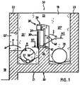
- FIG. 1 shows, as a first exemplary embodiment, a schematic and section view of a section of a sewage system, designated as a whole by 50, which essentially comprises a retention basin 10 partially shown and a relief basin 20 connected thereto via an overflow opening 22 '.
- the relief basin 20 has a bottom 21 and two spaced-apart side walls 22 and 23, a front wall 19 and rear wall 18 and an intermediate wall 24, which in the exemplary embodiment shown is arranged in the longitudinal direction of the relief basin 20.
- a pool space 25 formed by the floor 21 and by the side walls 22 and 23 and by the front and rear walls 19, 18 is divided by the intermediate wall 24 into a storage space (inflow space) 25 'and a discharge space 25' '.
- the overflow opening 22 ' extends largely over the entire length of the side wall 22.
- the storage space 25' is connected to an inflow line 26 penetrating the front wall 19 and an outflow line 27 penetrating the rear wall 18.
- a drain line 28 penetrating the rear wall 18 is assigned to the drain chamber 25 ′′.
- FIG. 1 a sieve screen unit 30 which is arranged on the intermediate wall 24 and is shown schematically and which, together with the upper edge 29, forms an emergency relief from the storage space 25 'to the drainage space 25''.
- the screen rake unit 30 comprises a diagrammatically shown screen rake 30 'with rake bars 31 arranged at a parallel distance from one another.
- the screen rake 30' is a cleaning carriage 35 which can be moved back and forth in the longitudinal direction (Fig. 2) assigned. If the screen rake 30 'is longer, a plurality of cleaning trolleys can also be provided.
- a preferred cleaning trolley which is provided with appropriately designed teeth and is arranged between the rake bars of the sieve rake, is known from EP-A 0 358 952 mentioned at the outset, wherein other cleaning elements which remove the sieve from floating substances can also be installed.
- baffle element 40 On the back or outflow side of the sieve rake 30 'there is a schematically illustrated baffle element 40 which is designed as a weir.
- the damming element 40 protruding into the discharge space 25 ′′ is arranged on the intermediate wall 24 inclined at an angle ⁇ with respect to the sieve ridges 30 ′ lying in the vertical plane and fastened by means not shown.
- a schematically shown holding and fastening device 41 is designed such that the baffle element 40 is adjustable in its relative position to the sieve 30 'and can be locked in the desired position.
- the relative position of the damming element 40 to the sieve screen 30 ' can be set and determined with suitable means, for example sensor-controlled, depending on the load which is dependent on the amount of water which arises.
- the level height N1 of the outflow from the storage space 25 ′ to the outflow space 25 ′′ is increased. This ensures that on the one hand the retention volume is increased and on the other hand the water pressure is largely distributed evenly over the entire surface of the screen. Furthermore, the flow rate of the water through the lower regions of the screen rake 30 'is reduced, as a result of which the floating substances can be retained better by the individual rake bars and an optimal cleaning effect is thus achieved. The reduction in flow rate also causes the existing floating substances are no longer carried away.
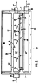
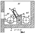
- the sewage system 50 is shown in a top view, and one can see the relief basin 20 arranged next to the partially and schematically shown retention basin 10, which essentially consists of the front wall 19 and the rear wall 18, the two side walls 22 and 23 and the intermediate wall 24 is formed. Furthermore, one can see the diagrammatically shown screen rake 30 'of the screen rake unit 30 as well as the cleaning carriage 35 which can be moved back and forth in the double arrow direction X by means not shown, which is provided with triangular teeth 36 arranged between the rake bars 31 of the screen rake 30'.
- the inflow line 26 is arranged on the front wall 19, through which the waste water or rainwater is supplied to the inflow space 25 'in the direction of the arrow 1.
- the wastewater is discharged through the line 27 in the direction of the arrow 1 ′′ and, at a certain level N, as shown in FIG. 1, through the opening 22 ′ in the direction of the arrow 1 ′ into the retention basin 10.
- a level N2 is reached, the wastewater is directed in the direction of arrow 2 through the sieve rake 30 'and over the upper edge of the damming element 40 into the drainage space 25' 'and discharged via the drain line 28 as water cleaned from floating substances in the direction of the arrow 3.
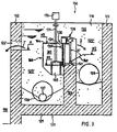
- FIG. 3 shows, as a second exemplary embodiment, a section of a wastewater system, designated schematically and in section, of a whole, designated 150, which essentially comprises a partially illustrated retention basin 110 and a first relief basin 120 connected thereto via an overflow opening 122 '.
- the waste water system 150 essentially corresponds to the waste water system 50 described above in connection with FIGS. 1 and 2.
- the waste water system 150 comprises the relief basin 120 consisting of a floor 121, two side walls 122 and 123, a front wall 119 and a rear wall 118, and an intermediate wall 124 oriented in the longitudinal direction of the relief basin 120.
- the side wall 122 there is a largely the entire length of the Side wall 122 extending overflow opening 122 'is provided.
- a pool space 125 formed by the floor 121 and by the side walls 122 and 123 as well as the front and rear wall 119, 118 is divided by the intermediate wall 124 into a storage space 125 'and a drainage space 125' '.
- FIG. 3 shows a screen screen unit 130, which is shown schematically and is arranged on the intermediate wall 124 and has a screen screen 130 'with rake bars 131 arranged parallel to one another.
- a cleaning carriage 135 (FIG. 4) which can be moved back and forth in the longitudinal direction is assigned to the screen rake 130 '.
- An upper edge of the screen unit 130 designated 129, essentially forms a so-called emergency relief from the storage space 125 'to the drainage space 125' '.
- baffle element 140 On the back or outflow side of the screen rake 130 'there is a schematically illustrated baffle element 140 which is designed as a weir.
- the damming element 140 projecting into the drainage space 125 ′′ is arranged and fastened to the intermediate wall 124 with respect to the screen rake 130 ′, inclined at an angle ⁇ ′.
- a schematically illustrated holding and fastening device 141 is designed such that the baffle element 140 is adjustable in its relative position to the sieve 130 'and in the desired position is noticeable.
- the relative position of the damming element 140 to the sieve screen 130 ' can be set and determined with suitable means, for example sensor-controlled, depending on the load which is dependent on the amount of water occurring.
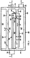
- the sewage system 150 is shown in plan view, and one can see the first relief basin 120 arranged next to the partially and schematically shown retention basin 110, which essentially consists of the front wall 119 and the rear wall 118, the two side walls 122 and 123 and the intermediate wall 124 is formed. Furthermore, one can see the diagrammatically shown sieve rake 130 'of the sieve rake unit 130 and the cleaning carriage 135 which can be moved back and forth in the double-arrow direction X' by means not shown, and which is provided with triangular teeth 136 arranged between the rake bars 131.
- the inflow line 126 is arranged on the front wall 119, through which the waste water is fed to the inflow space 125 ′ in the direction of the arrow 1.
- a second relief basin 160 assigned to the screen unit 130 is provided in the inflow space 125 'of the first relief basin 120.
- the second relief basin 160 forms a prechamber 161 upstream of the screen rake 130 ′, which has an overflow edge 164 in the upper region (FIG. 3).
- the prechamber 161 of the second relief basin 160 is, as shown in FIG. 4, divided to form a screen well 162 by a partition 163, the pre-chamber 161 being connected to the screen well 162 by an opening 162 '.
- the sieve shaft 162 serves to receive the sieve material fed from the sieve screen 130 '.
- a sliding element 165 for draining the sieved material (not shown) is provided for the sieved material shaft 162. To open and close the slide element 165, this is, as shown in FIG. 3, operatively connected to a drive 170 via a tension member 171.
- the wastewater supplied to the inflow space 125 ′ via the line 126 is discharged through the line 127 in the direction of the arrow 1 ′′.
- the waste water as shown in FIG. 3, is conducted into the retention basin 110 in the direction of the arrow 1 ′.
- the waste water reaches the antechamber 161 of the second relief basin 160 and is dammed up there until the level N2 of the additional damming element 140, which is increased in relation to the level N1 (overflow edge of the intermediate wall 124) is reached.
- the water flowing in the direction of the arrow 2 through the sieve rake 130 ′ over the damming element 140 reaches the drainage space 128 and is then discharged as water cleaned of floating substances.
- the baffle element 40 or 140 with respect to the screen unit 30 or 130 at an angle ⁇ or ⁇ 'on the order of 30 ° to 45 ° on the intermediate wall 24 or 124 or possibly also on the screen unit is arranged and fastened.
- the flow rate can be adjusted by the adjustable inclination of the damming element 40 or 140 with respect to the screen unit 30 or 130.
- FIGS. 1 and 2 show a modified embodiment of the exemplary embodiment according to FIGS. 1 and 2.
- This modified embodiment is correct with the exemplary embodiment with the exception of the changes specified below 1 and 2 completely correspond and is therefore not explained again in this respect.
- the embodiment according to FIG. 5 differs from that according to FIG. 1 in that the screen unit 30 is inclined, in such a way that its upper edge is tilted in the direction of the inflow space 25 '.
- the - in the embodiment according to FIG. 1 flat - surface of the intermediate wall 24 is also oriented obliquely, so that the screen unit 30 lies flat with its underside on the top of the intermediate wall 24 .
- the screen rake 30 ' is arranged on the side of the screen rake unit 30 facing the inflow space 25' and its bottom point essentially corresponds to the side face of the intermediate wall 24 facing the inflow area 25 ', the upper edge of the side face facing the drain space 25' 'lies the intermediate wall 24 is significantly higher than the lowest point of the screen rake 30 '.
- the inclined surface 224 of the intermediate wall 24 itself takes over the function of the baffle element 40 according to FIG. forms this dam element.
- a separate damming element can also be positively placed on the surface 224, for example in the form of a thin sheet, in order to protect the top 224 of the intermediate wall 24 against the action of the water flowing over it.
- the holding of the stowage element is thus drastically simplified or, as already stated, it can also be completely on a separate stowage element - with the exception of the inclined surface 224 of the intermediate wall 24 - are dispensed with, so that the effort is reduced accordingly.
- the baffle element can be formed in a particularly simple manner directly through the base plate of the screen unit 30 ', with which the screen unit 30' is mounted on the intermediate wall 24, covering the upper side 224 and possibly pulled down over the edges to the side surfaces of the intermediate wall 24.
- the base plate thus takes on the additional function of damming up the water level on the inflow side.
- tilting the screen unit 30 Another advantage of tilting the screen unit 30 is that the water can flow better out of the screen back to the inlet channel when the water level in the inlet channel begins to drop. In this way, the remaining residual water in the screen unit can be reliably avoided after the water level on the inlet side has dropped to normal level.
- the tilting of the screen rake unit has the advantage that the screenings can be wiped off better in the end positions of the cleaning comb, since the screenings fall better. There is therefore no risk of an undesirably large accumulation of screenings in the edge areas of the screen rack.
- the hydraulic unit mounted on the top of the screen 30 'and driving the cleaning comb (s) is located higher or further away from the drainage level, so that the risk of contamination or contamination of the hydraulic unit is reduced.
- the angle between the horizontal plane and the base plate of the screen unit 30 'or the upper side 224 of the intermediate wall 24 is 30 ° according to FIG. 5.
- the angle of inclination can be varied between 15 ° and 60 °. It is preferably between 30 ° and 40 °, since optimal results are achieved here with regard to the advantages explained above.
- FIG. 6 shows a modified embodiment of the exemplary embodiment according to FIGS. 3 and 4.
- the screen rake unit 130 is also inclined here as in the embodiment according to FIG. 5. All of the above statements regarding the inclined position of the screen rake unit, the design and arrangement of the damming element, the advantages which can be achieved by the inclined position, etc., which were explained above with reference to FIG. 5, also apply in an identical manner to the embodiment according to FIG. 6, so that reference is made to the above statements in order to avoid repetitions.
Landscapes
- Chemical & Material Sciences (AREA)
- Chemical Kinetics & Catalysis (AREA)
- Public Health (AREA)
- Water Supply & Treatment (AREA)
- Health & Medical Sciences (AREA)
- Life Sciences & Earth Sciences (AREA)
- Engineering & Computer Science (AREA)
- Hydrology & Water Resources (AREA)
- Business, Economics & Management (AREA)
- Emergency Management (AREA)
- Sewage (AREA)
- Filtration Of Liquid (AREA)
- Separation Of Suspended Particles By Flocculating Agents (AREA)
- Purification Treatments By Anaerobic Or Anaerobic And Aerobic Bacteria Or Animals (AREA)
- Sink And Installation For Waste Water (AREA)
- Sanitary Device For Flush Toilet (AREA)
- Sampling And Sample Adjustment (AREA)
- Materials For Photolithography (AREA)
Claims (13)
- Installation d'évacuation des eaux usées, constituée par un bassin de déversement (20;120) relié à au moins une canalisation d'amenée (26;126) et à au moins une canalisation d'évacuation (28;128), et par une unité à râteau de tamisage (30;130), disposée dans ce bassin et qui comprend un râteau de tamisage, constitué par des dents parallèles, ainsi qu'un chariot de nettoyage déplaçable en va-et-vient et sur lequel est fixé un peigne de nettoyage, dont les dents s'étendent entre les branches du râteau de tamisage, caractérisée en ce que le bassin de déversement (20;120) est subdivisé par une paroi intercalaire (24;124), en une chambre d'amenée (25';125') et une chambre d'évacuation (25'';125'') et que l'unité à râteau de tamisage (30; 130) est disposée sur la paroi intercalaire (24;124), et que pour accroître le volume de retenue, il est prévu un élément de retenue (40;140), qui est disposé dans la direction d'écoulement en arrière de l'unité formant râteau de tamisage (30;130) en étant incliné d'un angle (α;α') par rapport au plan vertical.
- Installation d'évacuation des eaux usées selon la revendication 1, caractérisée en ce que l'élément de retenue est fixé dans la chambre d'évacuation (25''; 125'') dans une position en saillie sur la paroi intercalaire (34;134).
- Installation d'évacuation des eaux usées selon la revendication 1 ou 2, caractérisée en ce que l'élément de retenue est fixé au bord supérieur oblique de la paroi intercalaire (24;124) ou est formé par cette paroi.
- Installation d'évacuation des eaux usées selon la revendication 1, 2 ou 3, caractérisée en ce que l'élément de retenue (40;140) est disposé de manière à faire, par rapport au plan vertical, un angle (α;α') de l'ordre de 30° à 45°.
- Installation d'évacuation des eaux usées selon l'une des revendications précédentes, caractérisée en ce que l'inclinaison de l'élément de retenue (40;140) par rapport à l'unité formant râteau de tamisage (30;130) peut être réglée et fixée en fonction de la quantité d'eau arrivante.
- Installation d'évacuation des eaux usées selon l'une des revendications précédentes, caractérisée en ce que le niveau en hauteur (N1) de la paroi intercalaire (24) se situe au-dessus du niveau en hauteur (N) d'une ouverture de débordement (22'), au moyen de laquelle le bassin de déchargement (20) est relié à un bassin de retenue associé (10).
- Installation d'évacuation des eaux usées selon l'une des revendications 1 à 5, caractérisée en ce que dans la chambre d'arrivée (125') est disposé un bassin de déchargement (160), qui est associé à l'unité formant râteau de tamisage (130) et est équipé d'une chambre amont (161) et qui possède un bord-déversoir (164) situé au-dessus de l'unité à râteau de tamisage (160).
- Installation d'évacuation des eaux usées selon la revendication 7, caractérisée en ce que le niveau en hauteur (N3) du bord-déversoir (164) du bassin de déchargement (160) est situé au-dessus du niveau en hauteur (N) d'une ouverture-déversoir (122'), par laquelle le bassin de déchargement (120) est relié à un bassin de retenue associé (110).
- Installation d'évacuation des eaux usées selon la revendication 7 ou 8, caractérisée en ce que l'inclinaison de l'élément de retenue (140) par rapport à l'unité à râteau de tamisage (130) peut être réglée et fixée, d'une manière commandée par un capteur, en fonction du niveau de l'eau dans la chambre amont (161).
- Installation d'évacuation des eaux usées selon la revendication 7, 8 ou 9, caractérisée en ce que la chambre amont (161) du bassin de déchargement (160) est équipée d'un conduit (162) pour la matière retenue par tamisage, qui est relié par l'intermédiaire d'une ouverture (162') à ce bassin et auquel un poussoir (165) est associé pour évacuer la matière retenue par tamisage.
- Installation d'évacuation des eaux usées selon la revendication 10, caractérisée en ce que le poussoir (165) peut être actionné pour l'ouverture et la fermeture par l'intermédiaire d'un organe de traction (171) relié selon une liaison active à un dispositif d'entraînement (170).
- Installation d'évacuation des eaux usées selon l'une des revendications précédentes, caractérisée en ce que le bord supérieur de l'unité à râteau de tamisage est basculé en direction de la chambre d'amenée.
- Installation d'évacuation des eaux usées selon la revendication 12, caractérisée en ce que l'angle de basculement de l'unité à râteau de tamisage (30;130) par rapport au plan vertical est compris entre 15° et 60° et de préférence entre 30° et 40°.
Applications Claiming Priority (3)
| Application Number | Priority Date | Filing Date | Title |
|---|---|---|---|
| CH3015/92 | 1992-09-25 | ||
| CH3015/92A CH685554A5 (de) | 1992-09-25 | 1992-09-25 | Abwasseranlage mit eingebauter Siebrecheneinheit. |
| PCT/EP1993/002594 WO1994007585A1 (fr) | 1992-09-25 | 1993-09-24 | Installation pour eaux usees avec ensemble grille de retenue incorpore |
Publications (2)
| Publication Number | Publication Date |
|---|---|
| EP0614397A1 EP0614397A1 (fr) | 1994-09-14 |
| EP0614397B1 true EP0614397B1 (fr) | 1997-02-12 |
Family
ID=4246728
Family Applications (1)
| Application Number | Title | Priority Date | Filing Date |
|---|---|---|---|
| EP93921848A Expired - Lifetime EP0614397B1 (fr) | 1992-09-25 | 1993-09-24 | Installation pour eaux usees avec ensemble grille de retenue incorpore |
Country Status (10)
| Country | Link |
|---|---|
| US (1) | US5490922A (fr) |
| EP (1) | EP0614397B1 (fr) |
| AT (1) | ATE148836T1 (fr) |
| CA (1) | CA2124327C (fr) |
| CH (1) | CH685554A5 (fr) |
| DE (1) | DE59305456D1 (fr) |
| DK (1) | DK0614397T3 (fr) |
| ES (1) | ES2097543T3 (fr) |
| GR (1) | GR3022562T3 (fr) |
| WO (1) | WO1994007585A1 (fr) |
Cited By (1)
| Publication number | Priority date | Publication date | Assignee | Title |
|---|---|---|---|---|
| DE102004014762A1 (de) * | 2004-03-26 | 2005-10-06 | Hans Huber Ag Maschinen- Und Anlagenbau | Abwasseranlage und Verfahren zum Betätigen eines Stauelements einer Abwasseranlage |
Families Citing this family (21)
| Publication number | Priority date | Publication date | Assignee | Title |
|---|---|---|---|---|
| US5849181A (en) * | 1997-06-02 | 1998-12-15 | Stormceptor Corporation | Catch basin |
| DE19801104C2 (de) * | 1998-01-15 | 2000-04-13 | Bormet Maschinenbau Gmbh | Siebrechen |
| GB9806071D0 (en) * | 1998-03-20 | 1998-05-20 | Tj Brent Limited | Raked bar screen |
| US6311905B1 (en) | 2000-02-07 | 2001-11-06 | Franklin Miller, Inc. | Screen cleaning and comminuting system |
| US6830207B2 (en) * | 2000-02-07 | 2004-12-14 | Franklin Miller, Inc. | Screen cleaning and comminuting system |
| DE60126292T2 (de) * | 2000-08-29 | 2007-05-31 | Hydro International Plc, Clevedon | Siebanordnung für eine überlaufschwelle für einen schmutzwasserkanal |
| DE20103875U1 (de) * | 2001-03-07 | 2001-08-16 | Vollmar Gmbh | Abwasseranlage mit Reinigungsvorrichtung |
| KR100429686B1 (ko) * | 2001-04-09 | 2004-05-03 | (주) 상원이엔씨 | 우수토실 유출조 |
| US6616834B2 (en) * | 2001-10-14 | 2003-09-09 | Jim Anderson | Wastewater processor |
| US7582216B2 (en) | 2007-08-22 | 2009-09-01 | Imbrium Systems Corp. | Water treatment and bypass system |
| EP2116649A3 (fr) | 2008-05-05 | 2011-07-13 | Jörg-Michael Dipl.-Ing. Steinhardt | Grille doté d'un dispositif pour enlever les déchets |
| WO2011035364A1 (fr) * | 2009-09-22 | 2011-03-31 | Water Solutions (Aust) Pty Ltd | Séparateur |
| IT1398752B1 (it) * | 2010-02-17 | 2013-03-18 | Friulana Costruzioni S R L | Dispositivo filtrante. |
| US8727248B2 (en) | 2010-08-11 | 2014-05-20 | William Galanty | Comminutor with screening conditioner |
| USD715409S1 (en) | 2012-04-05 | 2014-10-14 | Leo Michael Raimondi | Pipe vent fitting |
| CN105888037A (zh) * | 2016-04-06 | 2016-08-24 | 重庆大学 | 一种雨水跌水弃流集水装置 |
| CN105863031A (zh) * | 2016-04-06 | 2016-08-17 | 重庆大学 | 一种高效雨水跌水弃流集水装置 |
| USD853869S1 (en) | 2018-04-13 | 2019-07-16 | Silicon Controls Pty Ltd. | Telemetric device for asset monitoring and reporting |
| ES2909464B2 (es) * | 2020-11-05 | 2023-02-20 | Deyma La Mancha S L | Dispositivo de desbaste en pozos de gruesos, de una estación depuradora de aguas residuales |
| CN115544461B (zh) * | 2022-11-28 | 2023-04-28 | 成都同飞科技有限责任公司 | 一种雨污混接分析方法、系统、设备及介质 |
| CN116556499A (zh) * | 2023-06-05 | 2023-08-08 | 江苏全心建设有限公司 | 市政雨水收集系统 |
Family Cites Families (13)
| Publication number | Priority date | Publication date | Assignee | Title |
|---|---|---|---|---|
| US799829A (en) * | 1905-06-02 | 1905-09-19 | William L Church | Dam. |
| US909484A (en) * | 1907-06-24 | 1909-01-12 | Byron E Van Auken | Water-of-condensation-cleaning apparatus. |
| US1035480A (en) * | 1907-10-09 | 1912-08-13 | Milton Schnaier | Area-drain. |
| US1474938A (en) * | 1919-08-19 | 1923-11-20 | Samuel L Marsh | Grease interceptor |
| US1825169A (en) * | 1928-04-09 | 1931-09-29 | Wyckoff Munro | Fish guard for irrigation ditches |
| US1758743A (en) * | 1929-04-05 | 1930-05-13 | Harman Jay Floyd | Oil and water separator |
| GB487803A (en) * | 1937-11-04 | 1938-06-27 | Claude Suckling | An improved means of safeguarding a water intake against choking by debris |
| DE2743580A1 (de) * | 1977-09-28 | 1979-03-29 | Herbert Reppert | Spuelrechen fuer regenentlastungen in mischwasserkanaelen |
| US4134833A (en) * | 1977-09-29 | 1979-01-16 | Mccormick Dennis J | Water recycle unit-grey water clearifier |
| US4689145A (en) * | 1986-08-01 | 1987-08-25 | Mathews Lester R | Dry well filtration system |
| CH677001A5 (fr) * | 1988-09-05 | 1991-03-28 | Romag Roehren & Masch | |
| WO1992021837A1 (fr) * | 1991-05-30 | 1992-12-10 | Kevin John Banner | Deflecteur de debris et procede de filtration |
| US5277799A (en) * | 1991-09-13 | 1994-01-11 | Bransch Edward J | Pump compartment screening arrangement for a tank |
-
1992
- 1992-09-25 CH CH3015/92A patent/CH685554A5/de not_active IP Right Cessation
-
1993
- 1993-09-24 EP EP93921848A patent/EP0614397B1/fr not_active Expired - Lifetime
- 1993-09-24 DE DE59305456T patent/DE59305456D1/de not_active Expired - Lifetime
- 1993-09-24 ES ES93921848T patent/ES2097543T3/es not_active Expired - Lifetime
- 1993-09-24 CA CA002124327A patent/CA2124327C/fr not_active Expired - Fee Related
- 1993-09-24 DK DK93921848.3T patent/DK0614397T3/da active
- 1993-09-24 US US08/240,765 patent/US5490922A/en not_active Expired - Lifetime
- 1993-09-24 WO PCT/EP1993/002594 patent/WO1994007585A1/fr not_active Ceased
- 1993-09-24 AT AT93921848T patent/ATE148836T1/de not_active IP Right Cessation
-
1997
- 1997-02-13 GR GR970400191T patent/GR3022562T3/el unknown
Cited By (1)
| Publication number | Priority date | Publication date | Assignee | Title |
|---|---|---|---|---|
| DE102004014762A1 (de) * | 2004-03-26 | 2005-10-06 | Hans Huber Ag Maschinen- Und Anlagenbau | Abwasseranlage und Verfahren zum Betätigen eines Stauelements einer Abwasseranlage |
Also Published As
| Publication number | Publication date |
|---|---|
| CH685554A5 (de) | 1995-08-15 |
| DE59305456D1 (de) | 1997-03-27 |
| CA2124327C (fr) | 2005-02-15 |
| DK0614397T3 (da) | 1997-03-17 |
| CA2124327A1 (fr) | 1994-04-14 |
| EP0614397A1 (fr) | 1994-09-14 |
| ATE148836T1 (de) | 1997-02-15 |
| ES2097543T3 (es) | 1997-04-01 |
| WO1994007585A1 (fr) | 1994-04-14 |
| GR3022562T3 (en) | 1997-05-31 |
| US5490922A (en) | 1996-02-13 |
Similar Documents
| Publication | Publication Date | Title |
|---|---|---|
| WO1994007585A1 (fr) | Installation pour eaux usees avec ensemble grille de retenue incorpore | |
| DE69420395T2 (de) | Vorrichtung zur abtrennung von feststoffen aus einer strömenden flüssigkeit | |
| AT396801B (de) | Siebanordnung sowie verwendung der siebanordnung | |
| DE69401914T2 (de) | Verteil- und reguliereinheit | |
| EP0596052B1 (fr) | Procede et dispositif d'entree pour l'alimentation de dessableurs plats ou de bassins de decantation/bassin de decantation finale | |
| EP1366245B1 (fr) | Installation d'epuration des eaux usees equipee d'un dispositif de purification | |
| EP1090664B1 (fr) | Evacuation des boues flottantes | |
| EP0358952B1 (fr) | Grillage de tamis, notamment tamis pour l'eau pluviale | |
| AT400599B (de) | Siebrechenanordnung für überlaufbecken | |
| DE69810267T2 (de) | Geneigter abwasserrechen | |
| DE3403985A1 (de) | Filtriertrommel einer filtrieranlage fuer metallurgische schlacke | |
| DE4124006A1 (de) | Vorrichtung zum spuelen des rechens in einem regenueberlaufbecken sowie zum reinigen des beckens | |
| EP1632619B1 (fr) | Installation d'eau avec dispositif de commande du débordement | |
| DE2263549C3 (de) | Vorrichtung zum Auswaschen von Verunreinigungen aus körnigen Feststoffen | |
| DE19649814C2 (de) | Sedimentationsbecken mit rechteckigem Grundriß zum Abscheiden von Schlamm aus Abwasser | |
| DE19721629C1 (de) | Aufstromsortierer | |
| DE19820259C2 (de) | Vorrichtung zum Reinigen, Spülen und Waschen eines Abwasserstromes in einem Zulaufgerinne einer Kläranlage | |
| DE10033484A1 (de) | Ablaufeinrichtung | |
| DE1274044B (de) | In einen Abwasserkanal eingeschaltetes Ausgleichs- und Absetzbecken fuer Regenwassermit einer in einen Vorfluter entwaessernden UEberlaufrinne | |
| DE19618300C2 (de) | Durchströmte Tauchwand | |
| DE3821521A1 (de) | Klaerbecken | |
| DE19801104C2 (de) | Siebrechen | |
| DE9017739U1 (de) | Vorrichtung zum Sammeln und Abgeben von Feststoffen aus strömendem Wasser | |
| EP0305606B1 (fr) | Dispositif de filtration à nettoyage par contre-courant | |
| DE8916132U1 (de) | Siebrechen, insbesondere Regenwassersieb |
Legal Events
| Date | Code | Title | Description |
|---|---|---|---|
| PUAI | Public reference made under article 153(3) epc to a published international application that has entered the european phase |
Free format text: ORIGINAL CODE: 0009012 |
|
| AK | Designated contracting states |
Kind code of ref document: A1 Designated state(s): AT BE CH DE DK ES FR GB GR IE IT LI LU MC NL PT SE |
|
| 17P | Request for examination filed |
Effective date: 19941013 |
|
| GRAG | Despatch of communication of intention to grant |
Free format text: ORIGINAL CODE: EPIDOS AGRA |
|
| 17Q | First examination report despatched |
Effective date: 19951220 |
|
| GRAH | Despatch of communication of intention to grant a patent |
Free format text: ORIGINAL CODE: EPIDOS IGRA |
|
| GRAH | Despatch of communication of intention to grant a patent |
Free format text: ORIGINAL CODE: EPIDOS IGRA |
|
| GRAA | (expected) grant |
Free format text: ORIGINAL CODE: 0009210 |
|
| AK | Designated contracting states |
Kind code of ref document: B1 Designated state(s): AT BE CH DE DK ES FR GB GR IE IT LI LU MC NL PT SE |
|
| REF | Corresponds to: |
Ref document number: 148836 Country of ref document: AT Date of ref document: 19970215 Kind code of ref document: T |
|
| REG | Reference to a national code |
Ref country code: CH Ref legal event code: NV Representative=s name: ISLER & PEDRAZZINI AG Ref country code: CH Ref legal event code: EP |
|
| ITF | It: translation for a ep patent filed | ||
| GBT | Gb: translation of ep patent filed (gb section 77(6)(a)/1977) |
Effective date: 19970214 |
|
| REG | Reference to a national code |
Ref country code: DK Ref legal event code: T3 |
|
| REF | Corresponds to: |
Ref document number: 59305456 Country of ref document: DE Date of ref document: 19970327 |
|
| REG | Reference to a national code |
Ref country code: ES Ref legal event code: FG2A Ref document number: 2097543 Country of ref document: ES Kind code of ref document: T3 |
|
| ET | Fr: translation filed | ||
| REG | Reference to a national code |
Ref country code: GR Ref legal event code: FG4A Free format text: 3022562 |
|
| REG | Reference to a national code |
Ref country code: IE Ref legal event code: FG4D Free format text: 72046 |
|
| REG | Reference to a national code |
Ref country code: PT Ref legal event code: SC4A Free format text: AVAILABILITY OF NATIONAL TRANSLATION Effective date: 19970213 |
|
| PLBE | No opposition filed within time limit |
Free format text: ORIGINAL CODE: 0009261 |
|
| STAA | Information on the status of an ep patent application or granted ep patent |
Free format text: STATUS: NO OPPOSITION FILED WITHIN TIME LIMIT |
|
| 26N | No opposition filed | ||
| PG25 | Lapsed in a contracting state [announced via postgrant information from national office to epo] |
Ref country code: MC Free format text: LAPSE BECAUSE OF NON-PAYMENT OF DUE FEES Effective date: 19980331 |
|
| REG | Reference to a national code |
Ref country code: GB Ref legal event code: IF02 |
|
| PGFP | Annual fee paid to national office [announced via postgrant information from national office to epo] |
Ref country code: PT Payment date: 20020809 Year of fee payment: 10 |
|
| PGFP | Annual fee paid to national office [announced via postgrant information from national office to epo] |
Ref country code: SE Payment date: 20020812 Year of fee payment: 10 |
|
| PGFP | Annual fee paid to national office [announced via postgrant information from national office to epo] |
Ref country code: GR Payment date: 20020816 Year of fee payment: 10 |
|
| PGFP | Annual fee paid to national office [announced via postgrant information from national office to epo] |
Ref country code: BE Payment date: 20020830 Year of fee payment: 10 |
|
| PGFP | Annual fee paid to national office [announced via postgrant information from national office to epo] |
Ref country code: LU Payment date: 20020918 Year of fee payment: 10 |
|
| PGFP | Annual fee paid to national office [announced via postgrant information from national office to epo] |
Ref country code: NL Payment date: 20020930 Year of fee payment: 10 |
|
| PGFP | Annual fee paid to national office [announced via postgrant information from national office to epo] |
Ref country code: IE Payment date: 20030814 Year of fee payment: 11 |
|
| PGFP | Annual fee paid to national office [announced via postgrant information from national office to epo] |
Ref country code: CH Payment date: 20030922 Year of fee payment: 11 |
|
| PG25 | Lapsed in a contracting state [announced via postgrant information from national office to epo] |
Ref country code: LU Free format text: LAPSE BECAUSE OF NON-PAYMENT OF DUE FEES Effective date: 20030924 |
|
| PGFP | Annual fee paid to national office [announced via postgrant information from national office to epo] |
Ref country code: GB Payment date: 20030924 Year of fee payment: 11 |
|
| PG25 | Lapsed in a contracting state [announced via postgrant information from national office to epo] |
Ref country code: SE Free format text: LAPSE BECAUSE OF NON-PAYMENT OF DUE FEES Effective date: 20030925 |
|
| PG25 | Lapsed in a contracting state [announced via postgrant information from national office to epo] |
Ref country code: BE Free format text: LAPSE BECAUSE OF NON-PAYMENT OF DUE FEES Effective date: 20030930 |
|
| BERE | Be: lapsed |
Owner name: ROHREN UND MASCHINEN A.G. *ROMAG Effective date: 20030930 |
|
| PG25 | Lapsed in a contracting state [announced via postgrant information from national office to epo] |
Ref country code: PT Free format text: LAPSE BECAUSE OF NON-PAYMENT OF DUE FEES Effective date: 20040331 |
|
| PG25 | Lapsed in a contracting state [announced via postgrant information from national office to epo] |
Ref country code: NL Free format text: LAPSE BECAUSE OF NON-PAYMENT OF DUE FEES Effective date: 20040401 |
|
| PG25 | Lapsed in a contracting state [announced via postgrant information from national office to epo] |
Ref country code: GR Free format text: LAPSE BECAUSE OF NON-PAYMENT OF DUE FEES Effective date: 20040402 |
|
| EUG | Se: european patent has lapsed | ||
| NLV4 | Nl: lapsed or anulled due to non-payment of the annual fee |
Effective date: 20040401 |
|
| REG | Reference to a national code |
Ref country code: PT Ref legal event code: MM4A Free format text: LAPSE DUE TO NON-PAYMENT OF FEES Effective date: 20040331 |
|
| PGFP | Annual fee paid to national office [announced via postgrant information from national office to epo] |
Ref country code: FR Payment date: 20040830 Year of fee payment: 12 |
|
| PG25 | Lapsed in a contracting state [announced via postgrant information from national office to epo] |
Ref country code: IE Free format text: LAPSE BECAUSE OF NON-PAYMENT OF DUE FEES Effective date: 20040924 Ref country code: GB Free format text: LAPSE BECAUSE OF NON-PAYMENT OF DUE FEES Effective date: 20040924 |
|
| PG25 | Lapsed in a contracting state [announced via postgrant information from national office to epo] |
Ref country code: LI Free format text: LAPSE BECAUSE OF NON-PAYMENT OF DUE FEES Effective date: 20040930 Ref country code: CH Free format text: LAPSE BECAUSE OF NON-PAYMENT OF DUE FEES Effective date: 20040930 |
|
| GBPC | Gb: european patent ceased through non-payment of renewal fee |
Effective date: 20040924 |
|
| REG | Reference to a national code |
Ref country code: CH Ref legal event code: PL |
|
| REG | Reference to a national code |
Ref country code: IE Ref legal event code: MM4A |
|
| PGFP | Annual fee paid to national office [announced via postgrant information from national office to epo] |
Ref country code: ES Payment date: 20050905 Year of fee payment: 13 |
|
| PGFP | Annual fee paid to national office [announced via postgrant information from national office to epo] |
Ref country code: DK Payment date: 20050914 Year of fee payment: 13 Ref country code: AT Payment date: 20050914 Year of fee payment: 13 |
|
| PG25 | Lapsed in a contracting state [announced via postgrant information from national office to epo] |
Ref country code: FR Free format text: LAPSE BECAUSE OF NON-PAYMENT OF DUE FEES Effective date: 20060531 |
|
| REG | Reference to a national code |
Ref country code: FR Ref legal event code: ST Effective date: 20060531 |
|
| PG25 | Lapsed in a contracting state [announced via postgrant information from national office to epo] |
Ref country code: AT Free format text: LAPSE BECAUSE OF NON-PAYMENT OF DUE FEES Effective date: 20060924 |
|
| PGFP | Annual fee paid to national office [announced via postgrant information from national office to epo] |
Ref country code: IT Payment date: 20060930 Year of fee payment: 14 |
|
| PG25 | Lapsed in a contracting state [announced via postgrant information from national office to epo] |
Ref country code: DK Free format text: LAPSE BECAUSE OF NON-PAYMENT OF DUE FEES Effective date: 20061002 |
|
| REG | Reference to a national code |
Ref country code: DK Ref legal event code: EBP |
|
| REG | Reference to a national code |
Ref country code: ES Ref legal event code: FD2A Effective date: 20060925 |
|
| PG25 | Lapsed in a contracting state [announced via postgrant information from national office to epo] |
Ref country code: ES Free format text: LAPSE BECAUSE OF NON-PAYMENT OF DUE FEES Effective date: 20060925 |
|
| PG25 | Lapsed in a contracting state [announced via postgrant information from national office to epo] |
Ref country code: IT Free format text: LAPSE BECAUSE OF NON-PAYMENT OF DUE FEES Effective date: 20070924 |
|
| PGFP | Annual fee paid to national office [announced via postgrant information from national office to epo] |
Ref country code: DE Payment date: 20090916 Year of fee payment: 17 |
|
| REG | Reference to a national code |
Ref country code: DE Ref legal event code: R119 Ref document number: 59305456 Country of ref document: DE Effective date: 20110401 |
|
| PG25 | Lapsed in a contracting state [announced via postgrant information from national office to epo] |
Ref country code: DE Free format text: LAPSE BECAUSE OF NON-PAYMENT OF DUE FEES Effective date: 20110401 |