EP0612976A2 - Interféromètre à modulation de phase - Google Patents
Interféromètre à modulation de phase Download PDFInfo
- Publication number
- EP0612976A2 EP0612976A2 EP93119046A EP93119046A EP0612976A2 EP 0612976 A2 EP0612976 A2 EP 0612976A2 EP 93119046 A EP93119046 A EP 93119046A EP 93119046 A EP93119046 A EP 93119046A EP 0612976 A2 EP0612976 A2 EP 0612976A2
- Authority
- EP
- European Patent Office
- Prior art keywords
- phase
- interferometer
- frequency
- phase modulator
- arm
- Prior art date
- Legal status (The legal status is an assumption and is not a legal conclusion. Google has not performed a legal analysis and makes no representation as to the accuracy of the status listed.)
- Granted
Links
- 230000010363 phase shift Effects 0.000 claims abstract description 12
- 238000011156 evaluation Methods 0.000 claims abstract description 9
- 230000003287 optical effect Effects 0.000 claims description 10
- 238000005259 measurement Methods 0.000 claims description 6
- 238000001228 spectrum Methods 0.000 claims description 3
- 238000007796 conventional method Methods 0.000 claims description 2
- 230000001419 dependent effect Effects 0.000 claims description 2
- 230000005855 radiation Effects 0.000 claims description 2
- 230000001105 regulatory effect Effects 0.000 claims description 2
- 230000007704 transition Effects 0.000 claims 1
- 230000003750 conditioning effect Effects 0.000 abstract 1
- 238000001914 filtration Methods 0.000 description 3
- 238000000034 method Methods 0.000 description 2
- 238000005215 recombination Methods 0.000 description 2
- 230000006798 recombination Effects 0.000 description 2
- 230000001629 suppression Effects 0.000 description 2
- 238000013461 design Methods 0.000 description 1
- 238000001514 detection method Methods 0.000 description 1
- 238000010586 diagram Methods 0.000 description 1
- 238000006073 displacement reaction Methods 0.000 description 1
- 230000005284 excitation Effects 0.000 description 1
- 238000003384 imaging method Methods 0.000 description 1
- 230000005693 optoelectronics Effects 0.000 description 1
- 238000000926 separation method Methods 0.000 description 1
Images
Classifications
-
- G—PHYSICS
- G01—MEASURING; TESTING
- G01B—MEASURING LENGTH, THICKNESS OR SIMILAR LINEAR DIMENSIONS; MEASURING ANGLES; MEASURING AREAS; MEASURING IRREGULARITIES OF SURFACES OR CONTOURS
- G01B9/00—Measuring instruments characterised by the use of optical techniques
- G01B9/02—Interferometers
- G01B9/02049—Interferometers characterised by particular mechanical design details
- G01B9/02051—Integrated design, e.g. on-chip or monolithic
-
- G—PHYSICS
- G01—MEASURING; TESTING
- G01B—MEASURING LENGTH, THICKNESS OR SIMILAR LINEAR DIMENSIONS; MEASURING ANGLES; MEASURING AREAS; MEASURING IRREGULARITIES OF SURFACES OR CONTOURS
- G01B9/00—Measuring instruments characterised by the use of optical techniques
- G01B9/02—Interferometers
- G01B9/02001—Interferometers characterised by controlling or generating intrinsic radiation properties
- G01B9/0201—Interferometers characterised by controlling or generating intrinsic radiation properties using temporal phase variation
-
- G—PHYSICS
- G01—MEASURING; TESTING
- G01B—MEASURING LENGTH, THICKNESS OR SIMILAR LINEAR DIMENSIONS; MEASURING ANGLES; MEASURING AREAS; MEASURING IRREGULARITIES OF SURFACES OR CONTOURS
- G01B9/00—Measuring instruments characterised by the use of optical techniques
- G01B9/02—Interferometers
- G01B9/02015—Interferometers characterised by the beam path configuration
- G01B9/02027—Two or more interferometric channels or interferometers
- G01B9/02028—Two or more reference or object arms in one interferometer
-
- G—PHYSICS
- G01—MEASURING; TESTING
- G01B—MEASURING LENGTH, THICKNESS OR SIMILAR LINEAR DIMENSIONS; MEASURING ANGLES; MEASURING AREAS; MEASURING IRREGULARITIES OF SURFACES OR CONTOURS
- G01B9/00—Measuring instruments characterised by the use of optical techniques
- G01B9/02—Interferometers
- G01B9/02083—Interferometers characterised by particular signal processing and presentation
-
- G—PHYSICS
- G01—MEASURING; TESTING
- G01J—MEASUREMENT OF INTENSITY, VELOCITY, SPECTRAL CONTENT, POLARISATION, PHASE OR PULSE CHARACTERISTICS OF INFRARED, VISIBLE OR ULTRAVIOLET LIGHT; COLORIMETRY; RADIATION PYROMETRY
- G01J9/00—Measuring optical phase difference; Determining degree of coherence; Measuring optical wavelength
- G01J9/02—Measuring optical phase difference; Determining degree of coherence; Measuring optical wavelength by interferometric methods
-
- G—PHYSICS
- G01—MEASURING; TESTING
- G01B—MEASURING LENGTH, THICKNESS OR SIMILAR LINEAR DIMENSIONS; MEASURING ANGLES; MEASURING AREAS; MEASURING IRREGULARITIES OF SURFACES OR CONTOURS
- G01B2290/00—Aspects of interferometers not specifically covered by any group under G01B9/02
- G01B2290/45—Multiple detectors for detecting interferometer signals
-
- G—PHYSICS
- G01—MEASURING; TESTING
- G01J—MEASUREMENT OF INTENSITY, VELOCITY, SPECTRAL CONTENT, POLARISATION, PHASE OR PULSE CHARACTERISTICS OF INFRARED, VISIBLE OR ULTRAVIOLET LIGHT; COLORIMETRY; RADIATION PYROMETRY
- G01J1/00—Photometry, e.g. photographic exposure meter
- G01J1/42—Photometry, e.g. photographic exposure meter using electric radiation detectors
- G01J2001/4242—Modulated light, e.g. for synchronizing source and detector circuit
-
- G—PHYSICS
- G01—MEASURING; TESTING
- G01J—MEASUREMENT OF INTENSITY, VELOCITY, SPECTRAL CONTENT, POLARISATION, PHASE OR PULSE CHARACTERISTICS OF INFRARED, VISIBLE OR ULTRAVIOLET LIGHT; COLORIMETRY; RADIATION PYROMETRY
- G01J9/00—Measuring optical phase difference; Determining degree of coherence; Measuring optical wavelength
- G01J9/02—Measuring optical phase difference; Determining degree of coherence; Measuring optical wavelength by interferometric methods
- G01J2009/0249—Measuring optical phase difference; Determining degree of coherence; Measuring optical wavelength by interferometric methods with modulation
-
- G—PHYSICS
- G01—MEASURING; TESTING
- G01J—MEASUREMENT OF INTENSITY, VELOCITY, SPECTRAL CONTENT, POLARISATION, PHASE OR PULSE CHARACTERISTICS OF INFRARED, VISIBLE OR ULTRAVIOLET LIGHT; COLORIMETRY; RADIATION PYROMETRY
- G01J9/00—Measuring optical phase difference; Determining degree of coherence; Measuring optical wavelength
- G01J9/04—Measuring optical phase difference; Determining degree of coherence; Measuring optical wavelength by beating two waves of a same source but of different frequency and measuring the phase shift of the lower frequency obtained
Definitions
- the invention relates to a phase-modulated interferometer for evaluating phase shifts due to changes in optical path lengths in the measuring arm of the interferometer.
- it is used for precision length measuring systems, which preferably use the heterodyne method for evaluation.
- phase modulation can be implemented in the strip waveguide.
- Sideband suppression can be achieved with precisely defined electrical control of the modulator. This is how VOGES describes in IEEE Journ. Quant. Electr. QE-18 (1982), pp. 124-129 a defined electrical control of the modulator by sawtooth pulses with a defined return and thus achieves a sideband suppression of 40dB.
- the generation of such control signals is complex and requires a very high level of control.
- the invention is based on the object of realizing a phase-modulated interferometer which, without complicated control of the phase modulator, obtains superimposed signals from the measuring and reference arm of the interferometer which can be evaluated.
- m and n are positive integers, so that in the equation there are on the one hand even and on the other hand odd indices of the Bessel function.
- One or more signals of different frequencies for regulating the control signals are expediently filtered out from the superimposed signal.
- a phase modulator in each of the reference arms, so that only one of the two different sinusoidal control signals is modulated in each reference arm.
- a phase modulator in each of the measuring arms, the two different modulation frequencies being fed to each of these modulators.
- the basic idea of the invention lies in the idea of using a simple sine control of the phase modulator to achieve a signal structure of the superimposed signal from the measuring and reference arm signals which can be evaluated in a known manner with regard to phase shifts in the measuring arm.
- This is achieved according to the invention by modulating with two phase-coupled frequency-stable sinusoidal signals and filtering out a narrow-band frequency from the local signal which corresponds to both an odd harmonic of the first modulation frequency and an even harmonic of the second modulation frequency.
- the result of the filtering is a cosine signal that can be analyzed for phase shift in the usual way.
- phase-modulated interferometer With the phase-modulated interferometer according to the invention, it is possible, instead of the complicated sawtooth control, to achieve the same signal structure with a double sine control, which permits the evaluation of the phase shift and thus the desired path measurement.
- the simple sine control also has the advantage that corresponding electro-optical modulators can be implemented on integrated-optical chips (IOC) and thus an integrated-optical phase-modulated interferometer, in particular heterodyne interferometer, can be manufactured industrially for various technical applications.
- IOC integrated-optical chips
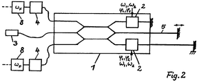
- FIG. 2 shows an integrated optical chip 1 for a three-armed interferometer with two reference arms. If the measuring and reference arms - as indicated schematically there - are arranged in the following reference arm - measuring arm - reference arm and if the measuring mirror moves in the interval between the two reference mirror positions, then a distance measurement of wavelength drifts of the laser diode 3 and changes in the optical properties can be carried out make the measuring section 5 independent.
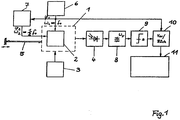
- this three-arm interferometer is a double interferometer with a common laser diode 3 and a common measuring section 5, because in each partial interferometer an excitation according to the invention of the phase modulator 2 with two modulation frequencies ⁇ 1 and ⁇ 2 is required in order to adjust the respective phase shift between the measuring arm and a reference arm via the detector 4 and to determine the bandpass filter 8 according to FIG. 1 and the prior art.
- the modulation frequencies ⁇ 1 and ⁇ 2 need not necessarily be chosen identically for the two phase modulators 2. It is also conceivable to use a single phase modulator 2 in the measuring arm before the measuring section 5 begins.
- a (not shown) three-armed interferometer with two measuring arms, preferably for coupled two-coordinate displacement measurement, is in principle constructed analogously to the interferometer according to FIG. 2, with the reference arm then is centered on the chip 1.
- the classification as a double interferometer with separate superimposition and evaluation remains the same.
Applications Claiming Priority (2)
| Application Number | Priority Date | Filing Date | Title |
|---|---|---|---|
| DE4305458 | 1993-02-23 | ||
| DE19934305458 DE4305458C2 (de) | 1993-02-23 | 1993-02-23 | Phasenmoduliertes Interferometer |
Publications (3)
| Publication Number | Publication Date |
|---|---|
| EP0612976A2 true EP0612976A2 (fr) | 1994-08-31 |
| EP0612976A3 EP0612976A3 (en) | 1995-09-20 |
| EP0612976B1 EP0612976B1 (fr) | 1997-01-29 |
Family
ID=6481080
Family Applications (1)
| Application Number | Title | Priority Date | Filing Date |
|---|---|---|---|
| EP93119046A Expired - Lifetime EP0612976B1 (fr) | 1993-02-23 | 1993-11-25 | Interféromètre à modulation de phase |
Country Status (4)
| Country | Link |
|---|---|
| US (1) | US5459571A (fr) |
| EP (1) | EP0612976B1 (fr) |
| AT (1) | ATE148554T1 (fr) |
| DE (1) | DE59305343D1 (fr) |
Cited By (3)
| Publication number | Priority date | Publication date | Assignee | Title |
|---|---|---|---|---|
| EP0614067B1 (fr) * | 1993-03-05 | 1997-03-05 | JENOPTIK Aktiengesellschaft | Interféromètre à modulation en phase |
| CN102589856A (zh) * | 2012-03-07 | 2012-07-18 | 清华大学 | 一种双频He-Ne激光器频率测量装置及其测量方法 |
| CN111351585A (zh) * | 2019-12-10 | 2020-06-30 | 西南技术物理研究所 | 一种使用锯齿波调相的相位测量方法 |
Families Citing this family (10)
| Publication number | Priority date | Publication date | Assignee | Title |
|---|---|---|---|---|
| GB9320500D0 (en) * | 1993-10-05 | 1993-11-24 | Rensihaw Plc | Interferometric distance measuring apparatus |
| JP3513247B2 (ja) * | 1994-07-11 | 2004-03-31 | キヤノン株式会社 | 周波数シフター及びそれを用いた光学式変位計測装置 |
| US20040166593A1 (en) * | 2001-06-22 | 2004-08-26 | Nolte David D. | Adaptive interferometric multi-analyte high-speed biosensor |
| US7365858B2 (en) * | 2001-12-18 | 2008-04-29 | Massachusetts Institute Of Technology | Systems and methods for phase measurements |
| US7557929B2 (en) | 2001-12-18 | 2009-07-07 | Massachusetts Institute Of Technology | Systems and methods for phase measurements |
| US6788420B1 (en) | 2002-01-29 | 2004-09-07 | The United States Of America As Represented By The Administrator Of The National Aeronautics And Space Administration | Heterodyne interferometer with a phase modulated source |
| DE10242777A1 (de) * | 2002-09-14 | 2004-04-08 | Robert Bosch Gmbh | Verfahren zum Bestimmen einer Entfernung und Entfernungsmessgerät |
| US7428054B2 (en) * | 2002-10-15 | 2008-09-23 | University Of Maryland | Micro-optical sensor system for pressure, acceleration, and pressure gradient measurements |
| US6901176B2 (en) * | 2002-10-15 | 2005-05-31 | University Of Maryland | Fiber tip based sensor system for acoustic measurements |
| US7224465B2 (en) * | 2002-10-15 | 2007-05-29 | University Of Maryland | Fiber tip based sensor system for measurements of pressure gradient, air particle velocity and acoustic intensity |
Citations (4)
| Publication number | Priority date | Publication date | Assignee | Title |
|---|---|---|---|---|
| US3563664A (en) * | 1967-11-09 | 1971-02-16 | James W Campbell | Method and apparatus for resolving transducer ambiguity |
| EP0290789A2 (fr) * | 1987-05-11 | 1988-11-17 | Hommelwerke GmbH | Dispositif pour la mesure de la distance entre le dispositif et une surface de mesure |
| EP0444843A2 (fr) * | 1990-03-02 | 1991-09-04 | Hitachi, Ltd. | Capteurs interférentiels et méthodes pour mesurer une grandeur physique utilisant tel capteurs aussi bien que système de contrôle d'un véhicule |
| EP0448751A1 (fr) * | 1990-03-27 | 1991-10-02 | Wolfgang Prof. Dr. Sohler | Interféromètre hétérodyne acousto-optique intégré |
Family Cites Families (5)
| Publication number | Priority date | Publication date | Assignee | Title |
|---|---|---|---|---|
| US4422764A (en) * | 1980-12-12 | 1983-12-27 | The University Of Rochester | Interferometer apparatus for microtopography |
| GB2233445A (en) * | 1989-06-24 | 1991-01-09 | British Aerospace | Ring resonator gyro |
| GB8921341D0 (en) * | 1989-09-21 | 1989-11-08 | Smiths Industries Plc | Optical multiplexing |
| US5212825A (en) * | 1990-11-09 | 1993-05-18 | Litton Systems, Inc. | Synthetic heterodyne demodulator circuit |
| US5319438A (en) * | 1992-01-24 | 1994-06-07 | Board Of Regents, The University Of Texas System | Interferometric, self-homodyne optical receiver and method and optical transmission system incorporating same |
-
1993
- 1993-11-25 DE DE59305343T patent/DE59305343D1/de not_active Expired - Fee Related
- 1993-11-25 EP EP93119046A patent/EP0612976B1/fr not_active Expired - Lifetime
- 1993-11-25 AT AT93119046T patent/ATE148554T1/de not_active IP Right Cessation
-
1994
- 1994-02-01 US US08/189,931 patent/US5459571A/en not_active Expired - Fee Related
Patent Citations (4)
| Publication number | Priority date | Publication date | Assignee | Title |
|---|---|---|---|---|
| US3563664A (en) * | 1967-11-09 | 1971-02-16 | James W Campbell | Method and apparatus for resolving transducer ambiguity |
| EP0290789A2 (fr) * | 1987-05-11 | 1988-11-17 | Hommelwerke GmbH | Dispositif pour la mesure de la distance entre le dispositif et une surface de mesure |
| EP0444843A2 (fr) * | 1990-03-02 | 1991-09-04 | Hitachi, Ltd. | Capteurs interférentiels et méthodes pour mesurer une grandeur physique utilisant tel capteurs aussi bien que système de contrôle d'un véhicule |
| EP0448751A1 (fr) * | 1990-03-27 | 1991-10-02 | Wolfgang Prof. Dr. Sohler | Interféromètre hétérodyne acousto-optique intégré |
Cited By (3)
| Publication number | Priority date | Publication date | Assignee | Title |
|---|---|---|---|---|
| EP0614067B1 (fr) * | 1993-03-05 | 1997-03-05 | JENOPTIK Aktiengesellschaft | Interféromètre à modulation en phase |
| CN102589856A (zh) * | 2012-03-07 | 2012-07-18 | 清华大学 | 一种双频He-Ne激光器频率测量装置及其测量方法 |
| CN111351585A (zh) * | 2019-12-10 | 2020-06-30 | 西南技术物理研究所 | 一种使用锯齿波调相的相位测量方法 |
Also Published As
| Publication number | Publication date |
|---|---|
| EP0612976B1 (fr) | 1997-01-29 |
| ATE148554T1 (de) | 1997-02-15 |
| DE59305343D1 (de) | 1997-03-13 |
| EP0612976A3 (en) | 1995-09-20 |
| US5459571A (en) | 1995-10-17 |
Similar Documents
| Publication | Publication Date | Title |
|---|---|---|
| EP0977973B1 (fr) | Montage pour la mise en forme de signaux apparaissant dans un interferometre heterodyne | |
| DE3326555C2 (fr) | ||
| DE19522262C2 (de) | Heterodyn-Interferometer-Anordnung | |
| DE3306709C2 (fr) | ||
| DE19738328B4 (de) | Interferometrische Vorrichtung zur Messung von Bewegungen eines Objektträgers relativ zu festen Reflektoren | |
| EP0612976B1 (fr) | Interféromètre à modulation de phase | |
| DE19528676A1 (de) | Interferometeranordnung zur absoluten Distanzmessung | |
| DE102005023489B4 (de) | Positionsmesseinrichtung zur Bestimmung der Position zweier entlang einer Messrichtung zueinander beweglicher Objekte und Verfahren zur Bildung eines Referenzimpulses für eine derartige Positionsmesseinrichtung | |
| DE19537647C1 (de) | Verfahren und Anordnung zur Messung physikalischer Größen von lichtstreuenden bewegten Teilchen mittels eines Laser-Doppler-Anemometers | |
| WO1993005364A1 (fr) | Detecteur optique pour mouvements de rotation | |
| EP1649242B1 (fr) | Procede de determination de l'indice de refraction lors de mesures de longueurs interferometriques et dispositif interferometrique correspondant | |
| DE4305458C2 (de) | Phasenmoduliertes Interferometer | |
| EP0614067B1 (fr) | Interféromètre à modulation en phase | |
| EP0492225A2 (fr) | Dispositif comprenant deux diodes laser pour la production de lumière à deux longueurs d'ondes | |
| EP0636858A1 (fr) | Interféromètre à modulation en phase | |
| DE4306884C2 (de) | Phasenmoduliertes Interferometer | |
| DE4035373C2 (de) | Faseroptischer Druck- oder Verschiebungsfühler | |
| EP0646766A2 (fr) | Procédé et dispositif pour l'interférométrie absolue avec du rayonnement à diode-laser | |
| DE10346379B4 (de) | Verfahren zum Bestimmen des Frequenzgangs eines elektrooptischen Bauelements | |
| DE1960116C3 (de) | Vorrichtung zur Bestimmung der Verschiebung eines Gegenstandes mit Hilfe eines mit dem Gegenstand mechanisch starr verbundenen Gitters | |
| DE3816755C3 (de) | Vorrichtung zum berührungslosen Erfassen der durch Ultraschallwellen verursachten Oberflächenauslenkung eines Prüflings | |
| EP0576885B1 (fr) | Interféromètre multi-bras | |
| DE4114253A1 (de) | Faseroptischer sensor | |
| EP1064517B1 (fr) | Procede et dispositif de mesure de longueur interferometrique absolue | |
| DE102022120607A1 (de) | Optische Vorrichtung, System und Verfahren zur Dispersionsinterferometrie |
Legal Events
| Date | Code | Title | Description |
|---|---|---|---|
| PUAI | Public reference made under article 153(3) epc to a published international application that has entered the european phase |
Free format text: ORIGINAL CODE: 0009012 |
|
| AK | Designated contracting states |
Kind code of ref document: A2 Designated state(s): AT CH DE FR GB IT LI |
|
| PUAL | Search report despatched |
Free format text: ORIGINAL CODE: 0009013 |
|
| AK | Designated contracting states |
Kind code of ref document: A3 Designated state(s): AT CH DE FR GB IT LI |
|
| 17P | Request for examination filed |
Effective date: 19950901 |
|
| GRAG | Despatch of communication of intention to grant |
Free format text: ORIGINAL CODE: EPIDOS AGRA |
|
| GRAH | Despatch of communication of intention to grant a patent |
Free format text: ORIGINAL CODE: EPIDOS IGRA |
|
| 17Q | First examination report despatched |
Effective date: 19960328 |
|
| RAP1 | Party data changed (applicant data changed or rights of an application transferred) |
Owner name: JENOPTIK AKTIENGESELLSCHAFT |
|
| GRAH | Despatch of communication of intention to grant a patent |
Free format text: ORIGINAL CODE: EPIDOS IGRA |
|
| GRAA | (expected) grant |
Free format text: ORIGINAL CODE: 0009210 |
|
| AK | Designated contracting states |
Kind code of ref document: B1 Designated state(s): AT CH DE FR GB IT LI |
|
| REF | Corresponds to: |
Ref document number: 148554 Country of ref document: AT Date of ref document: 19970215 Kind code of ref document: T |
|
| REG | Reference to a national code |
Ref country code: CH Ref legal event code: NV Representative=s name: DR. P. FILLINGER PATENTANWALT AG Ref country code: CH Ref legal event code: EP |
|
| ITF | It: translation for a ep patent filed |
Owner name: JACOBACCI & PERANI S.P.A. |
|
| GBT | Gb: translation of ep patent filed (gb section 77(6)(a)/1977) |
Effective date: 19970203 |
|
| REF | Corresponds to: |
Ref document number: 59305343 Country of ref document: DE Date of ref document: 19970313 |
|
| ET | Fr: translation filed | ||
| ET | Fr: translation filed |
Free format text: CORRECTIONS |
|
| PGFP | Annual fee paid to national office [announced via postgrant information from national office to epo] |
Ref country code: AT Payment date: 19971128 Year of fee payment: 5 |
|
| PLBE | No opposition filed within time limit |
Free format text: ORIGINAL CODE: 0009261 |
|
| STAA | Information on the status of an ep patent application or granted ep patent |
Free format text: STATUS: NO OPPOSITION FILED WITHIN TIME LIMIT |
|
| 26N | No opposition filed | ||
| PG25 | Lapsed in a contracting state [announced via postgrant information from national office to epo] |
Ref country code: DE Free format text: LAPSE BECAUSE OF NON-PAYMENT OF DUE FEES Effective date: 19980801 |
|
| PG25 | Lapsed in a contracting state [announced via postgrant information from national office to epo] |
Ref country code: AT Free format text: LAPSE BECAUSE OF NON-PAYMENT OF DUE FEES Effective date: 19981125 |
|
| PGFP | Annual fee paid to national office [announced via postgrant information from national office to epo] |
Ref country code: FR Payment date: 20001110 Year of fee payment: 8 |
|
| PGFP | Annual fee paid to national office [announced via postgrant information from national office to epo] |
Ref country code: GB Payment date: 20001122 Year of fee payment: 8 |
|
| PGFP | Annual fee paid to national office [announced via postgrant information from national office to epo] |
Ref country code: CH Payment date: 20001128 Year of fee payment: 8 |
|
| PG25 | Lapsed in a contracting state [announced via postgrant information from national office to epo] |
Ref country code: GB Free format text: LAPSE BECAUSE OF NON-PAYMENT OF DUE FEES Effective date: 20011125 |
|
| PG25 | Lapsed in a contracting state [announced via postgrant information from national office to epo] |
Ref country code: LI Free format text: LAPSE BECAUSE OF NON-PAYMENT OF DUE FEES Effective date: 20011130 Ref country code: CH Free format text: LAPSE BECAUSE OF NON-PAYMENT OF DUE FEES Effective date: 20011130 |
|
| REG | Reference to a national code |
Ref country code: GB Ref legal event code: IF02 |
|
| REG | Reference to a national code |
Ref country code: CH Ref legal event code: PL |
|
| GBPC | Gb: european patent ceased through non-payment of renewal fee |
Effective date: 20011125 |
|
| PG25 | Lapsed in a contracting state [announced via postgrant information from national office to epo] |
Ref country code: FR Free format text: LAPSE BECAUSE OF NON-PAYMENT OF DUE FEES Effective date: 20020730 |
|
| REG | Reference to a national code |
Ref country code: FR Ref legal event code: ST |
|
| REG | Reference to a national code |
Ref country code: FR Ref legal event code: ST |
|
| PG25 | Lapsed in a contracting state [announced via postgrant information from national office to epo] |
Ref country code: IT Free format text: LAPSE BECAUSE OF NON-PAYMENT OF DUE FEES;WARNING: LAPSES OF ITALIAN PATENTS WITH EFFECTIVE DATE BEFORE 2007 MAY HAVE OCCURRED AT ANY TIME BEFORE 2007. THE CORRECT EFFECTIVE DATE MAY BE DIFFERENT FROM THE ONE RECORDED. Effective date: 20051125 |