EP0612958B1 - Fuel burner apparatus and method employing divergent flow nozzle - Google Patents
Fuel burner apparatus and method employing divergent flow nozzle Download PDFInfo
- Publication number
- EP0612958B1 EP0612958B1 EP94300509A EP94300509A EP0612958B1 EP 0612958 B1 EP0612958 B1 EP 0612958B1 EP 94300509 A EP94300509 A EP 94300509A EP 94300509 A EP94300509 A EP 94300509A EP 0612958 B1 EP0612958 B1 EP 0612958B1
- Authority
- EP
- European Patent Office
- Prior art keywords
- oxidant
- fuel
- jet
- combustion
- nozzle means
- Prior art date
- Legal status (The legal status is an assumption and is not a legal conclusion. Google has not performed a legal analysis and makes no representation as to the accuracy of the status listed.)
- Expired - Lifetime
Links
Images


Classifications
-
- F—MECHANICAL ENGINEERING; LIGHTING; HEATING; WEAPONS; BLASTING
- F23—COMBUSTION APPARATUS; COMBUSTION PROCESSES
- F23D—BURNERS
- F23D14/00—Burners for combustion of a gas, e.g. of a gas stored under pressure as a liquid
- F23D14/20—Non-premix gas burners, i.e. in which gaseous fuel is mixed with combustion air on arrival at the combustion zone
- F23D14/22—Non-premix gas burners, i.e. in which gaseous fuel is mixed with combustion air on arrival at the combustion zone with separate air and gas feed ducts, e.g. with ducts running parallel or crossing each other
-
- F—MECHANICAL ENGINEERING; LIGHTING; HEATING; WEAPONS; BLASTING
- F23—COMBUSTION APPARATUS; COMBUSTION PROCESSES
- F23C—METHODS OR APPARATUS FOR COMBUSTION USING FLUID FUEL OR SOLID FUEL SUSPENDED IN A CARRIER GAS OR AIR
- F23C6/00—Combustion apparatus characterised by the combination of two or more combustion chambers or combustion zones, e.g. for staged combustion
- F23C6/04—Combustion apparatus characterised by the combination of two or more combustion chambers or combustion zones, e.g. for staged combustion in series connection
- F23C6/045—Combustion apparatus characterised by the combination of two or more combustion chambers or combustion zones, e.g. for staged combustion in series connection with staged combustion in a single enclosure
-
- F—MECHANICAL ENGINEERING; LIGHTING; HEATING; WEAPONS; BLASTING
- F23—COMBUSTION APPARATUS; COMBUSTION PROCESSES
- F23D—BURNERS
- F23D14/00—Burners for combustion of a gas, e.g. of a gas stored under pressure as a liquid
- F23D14/32—Burners for combustion of a gas, e.g. of a gas stored under pressure as a liquid using a mixture of gaseous fuel and pure oxygen or oxygen-enriched air
-
- F—MECHANICAL ENGINEERING; LIGHTING; HEATING; WEAPONS; BLASTING
- F23—COMBUSTION APPARATUS; COMBUSTION PROCESSES
- F23C—METHODS OR APPARATUS FOR COMBUSTION USING FLUID FUEL OR SOLID FUEL SUSPENDED IN A CARRIER GAS OR AIR
- F23C2201/00—Staged combustion
- F23C2201/20—Burner staging
-
- F—MECHANICAL ENGINEERING; LIGHTING; HEATING; WEAPONS; BLASTING
- F23—COMBUSTION APPARATUS; COMBUSTION PROCESSES
- F23D—BURNERS
- F23D2900/00—Special features of, or arrangements for burners using fluid fuels or solid fuels suspended in a carrier gas
- F23D2900/00006—Liquid fuel burners using pure oxygen or oxygen-enriched air as oxidant
-
- F—MECHANICAL ENGINEERING; LIGHTING; HEATING; WEAPONS; BLASTING
- F23—COMBUSTION APPARATUS; COMBUSTION PROCESSES
- F23D—BURNERS
- F23D2900/00—Special features of, or arrangements for burners using fluid fuels or solid fuels suspended in a carrier gas
- F23D2900/00012—Liquid or gas fuel burners with flames spread over a flat surface, either premix or non-premix type, e.g. "Flächenbrenner"
- F23D2900/00013—Liquid or gas fuel burners with flames spread over a flat surface, either premix or non-premix type, e.g. "Flächenbrenner" with means for spreading the flame in a fan or fishtail shape over a melting bath
Definitions
- the present invention relates to a fuel burner apparatus and method for burning a fuel in an oxidant. More particularly, the present invention relates to such a fuel burner apparatus and method in which the oxidant is oxygen or oxygen enriched air.
- the present invention also relates to a nozzle that is capable of producing a flat, divergent uniform flow of a fluid that is particularly suited for forming oxidant nozzles used in a fuel burner apparatus and method in accordance with the present invention.
- Fuel burners are used in many industrial applications in which a material to be processed is melted, for example, glass, copper, aluminium, iron, and steel.
- oxy-fuel burners have evolved in which the fuel is burned in oxygen or oxygen enriched air.
- These burners generally produce flames having a highly concentrated power output which can in turn produce hot spots in the melt.
- such burners utilise high velocity oxidant and high mass flow rates of fuel to produce the high power outputs.
- the concentrated heating tends to evolve volatiles within the melt and the high velocities tend to entrain feed material to the exhaust of the furnace.
- the entrained feed material and evolved volatiles can thereby be lost and pollute the atmosphere or can form a deposit which accumulates within the furnace or exhaust heat recovery systems used in conjunction with furnaces.
- a still further problem in oxy-fuel burners is that the high temperature combustion of the fuel in oxygen or oxygen enriched air can produce polluting NO x .
- the present invention provides a burner apparatus and method that is less susceptible than prior art apparatus and methodology to forming hot spots and entraining feed particles within the flow of oxidant and fuel and further, is readily adaptable to employ a NO x limiting form of combustion.
- the present invention provides a method of burning fuel in an oxidant comprising producing a fuel jet of outwardly divergent, fan-shaped configuration so that the fuel jet will burn within the oxidant with an outwardly extending and divergent flame; and producing a lower oxidant jet separate and distinct from the fuel jet and below the fuel jet, characterised by producing an upper oxidant jet separate and distinct from the lower oxidant jet and from the fuel jet and above the fuel jet, and by producing the oxidant jets so as to have a lower velocity than the fuel jet such that the oxidant is aspirated into the fuel.
- the present invention also provides a burner for burning fuel in an oxidant comprising fuel nozzle means for producing a fuel jet of outwardly divergent, fan-shaped configuration, the fuel jet adapted to burn within the oxidant with an outwardly extending and divergent flame, and lower oxidant nozzle means separate and distinct from the fuel nozzle means for producing a lower oxidant jet of outwardly divergent, fan-shaped configuration located below the fuel jet, characterised in that upper oxidant nozzle means are provided, separate and distinct from the lower oxidant nozzle means and from the fuel nozzle means, for producing an upper oxidant jet of outwardly-divergent, fan-shaped configuration located above the fuel jet, in that each of the upper and lower oxidant nozzle means comprises a passageway having an outlet for discharging the oxidant and an inlet to the passageway for introducing a flow of the oxidant into the passageway, and means dividing the passageways in a lengthwise direction thereof and the flow of the oxidant into a plurality of subflows having
- the fuel jet and oxidant nozzle are outwardly divergent and fan-shaped to produce an outwardly extending flame burning over a wide area.
- the wide area of combustion has the advantage of permitting high levels of heat input into a melt while eliminating hot spots within the melt.
- the upper and lower oxidant nozzle means produce low velocity and therefore high pressure oxidant jets which in turn produces a pressure differential to aspirate the oxidant into the fuel. Since, however, the oxidant jets are of low velocity, they tend not to entrain feed particles and thus serve to shield the fuel jet.
- a nozzle for producing a flat, uniformly divergent flow of a fluid which nozzle is particularly well suited for serving as the upper and lower oxidant nozzle means, comprises a body portion including a passageway.
- the passageway has an outlet for discharging a fluid flow and an inlet to the passageway for introducing the fluid flow into the passageway.
- a means is provided for dividing the passageway in a lengthwise direction thereof and thus, the flow of the fluid into a plurality of subflows having velocities of essentially equal magnitude and oriented so as to gradually diverge in a transverse direction of the flow of the fluid.
- the present invention can be adapted to reduce NO x formation.
- atmospheric nitrogen can react with oxygen to produce thermal NO x .
- fuel radicals such as CH can react with atmospheric nitrogen to form prompt NO x .
- combustion of the fuel occurs in two stages in order to reduce both thermal and prompt NO x formation. In a first of the two stages of combustion, combustion of the fuel within the oxidant supplied by the upper and lower oxidant jets is substoichiometric.
- the burner further comprises secondary upper and lower oxidant nozzle means separate and distinct from one another and the upper and lower oxidant nozzle and fuel jet means.
- the upper and lower oxidant nozzle and fuel jet means produce at least one pair of upper and lower secondary oxidant jets of outwardly divergent, fan-shaped configuration located above and below the upper and lower oxidant jets, respectively, for supplying sufficient amounts of oxidant to complete combustion of the fuel.
- the combustion of the fuel is thereby completed in a second of two stages of combustion.
- the sufficient amounts of oxidant can either be just that required to complete combustion or alternatively, can be in superstoichiometric amounts.
- the methodology involved in this aspect of the present invention comprises producing at least one pair of upper and lower secondary oxidant jets of outwardly divergent, fan-shaped configurations at locations above and below the upper and lower oxidant jets, respectively, so as to supply sufficient amounts of oxidant to complete combustion of the fuel.
- This staging of combustion has been found to lower NO x formation.
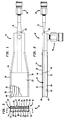
- Burner 10 includes a fuel nozzle 12, which, as will be described, is designed to produce a fuel jet of outwardly divergent, fan-shaped configuration. Such a fuel jet will burn within suitably shaped oxidant jets with an outwardly extending and divergent flame.
- Upper and lower oxidant nozzles 14 and 16 are provided for producing upper and lower oxidant jets of outwardly divergent, fan-shaped configuration located above and below the fuel jet.
- the upper and lower oxidant jets of upper and lower oxidant nozzles 14 and 16 have a lower velocity than the fuel jet.
- Burner 10 is specifically designed to burn natural gas in an oxidant of essentially pure oxygen. It is understood that more generally the teachings set forth herein have applicability to different fuel gases such as hydrogen, ethane, propane, butane, acetylene and liquid fuels such as diesel fuel, heating oils, etc. Additionally the oxidant can be oxygen enriched air.
- lower oxidant nozzle means 16 can be designed such that the lower oxidant jet has a higher mass flow rate than that of the upper oxidant jet issuing from upper oxidant nozzle 14. This will result in the combustion of the fuel being primarily in oxidant supplied by the lower oxidant jet of higher mass flow rate with the increasingly more buoyant unburned fuel burning in the oxidant supplied by the upper oxidant jet.
- an embodiment of the present invention could be constructed with upper and lower oxidant nozzles producing oxidant jets of equal mass flow rates.
- Burner 10 is provided with a body 18 of elongated configuration having top and bottom walls 20 and 22 and side walls 24 and 26. Angled reinforcement members 28-34 are provided to stiffen body portion 18. Central fuel nozzle 12 divides body portion 18 into upper and lower oxidant nozzles 14 and 16 which include upper and lower passageways 36 and 38 having outlets 40 and 42 and inlets 44 and 46.
- a coupling assembly 48 is connected to the rear of body portion 18 to introduce oxidant into body portion 18 which in turn flows into inlets 44 and 46 of upper and lower oxidant nozzles 14 and 16 and thereafter, flows of outlets 40 and 42 thereof.
- Fuel nozzle 12 is supported within body 18 by upper and lower sets of vanes 50 and 52. Vanes 50 and 52 are connected to top and bottom walls 20 and 22 and to fuel nozzle 12. Vanes 50 and 52 divide passageways 36 and 38 in the lengthwise direction and therefore the flow of oxidant passing through upper and lower passageways 36 and 38 into a plurality of subflows. Vanes 50 and 52 are specifically designed such that the velocities of the subflows will have an essentially equal magnitude and be oriented so as to gradually diverge in a transverse direction to the flow of the oxidant.
- vanes 50 and 52 which are designed such that tangents drawn at their maximum curvatures all intersect at one location within the respective of the passageways 40 and 42 of which vanes 50 and 52 subdivide. Although hidden, the vanes extend rearwardly to the inlets 44 and 46 of upper and lower oxidant nozzles 14 and 16.
- a further advantage of the vaned upper and lower oxidant nozzles is that the vanes allow for effective self cooling of burner 10 without external water cooling.
- upper and lower oxidant nozzles 14 and 16 are designed such that the lower oxidant jet will have a higher mass flow rate than the upper oxidant nozzle jet. This is effected by appropriately sizing the rectangular, transverse cross-section of upper and lower oxidant nozzles to be in a ratio of cross-sectional areas smaller than unity. The ratios are preferably in a range of between about 0.125 and about 0.5.
- oxidant nozzles 14 and 16 could be used in other applications.
- an oxidant nozzle could be designed in the manner provided herein for use in creating a flat, fan-shaped outwardly divergent field of oxidant below a fuel jet or burner or in other words, for oxygen-lancing purposes.
- fuel nozzle 12 is preferably formed in two sections 56 and 58.
- Fuel nozzle 12 is in the form therefore of a central body portion having a chamber 60 and a plurality of passageways 62 of equal length, spaced apart from one another, and gradually fanning out from chamber 60.
- Chamber 60 communicates between passages 62 and a fuel inlet 64 such that fuel flows from fuel inlet 64 and out of passages 62.
- Passages 62 gradually fan out from chamber 60 so that the resultant fuel jet will fan out.
- the equal length of passages 62 produce an equal pressure drop and therefore equal velocity so that the fuel jet will fan out or horizontally diverge with little decay.
- the ratio of the average velocities of the fuel versus oxidant is approximately 13.5 to 1.0.
- a conduit 66 of rectangular-transverse cross-section connects to a coupling 68 by means of a transition piece 70 which transitions from a circular, transverse cross-section to a rectangular, transverse cross-section. If fuel nozzle 12 were to be employed to burn liquid fuels, suitable fuel nozzles (known well in the art) would have to be attached to passages 62.
- FIGs. 5, 6 and 7 an alternative embodiment of a fuel burner apparatus of the present invention is illustrated.
- the illustrated embodiment stages oxidant into the fuel to reduce polluting NO x emissions while producing a flame pattern illustrated in Figs. 8 and 9 which is horizontally divergent, fan-shaped and resistant to decay along the length of the flame pattern.
- This is effected with the use of burner 10 such that fuel and oxidant is supplied from oxidant nozzles 14 and 16 in substoichiometric amounts or in other words the oxidant supplied does not completely support combustion of the fuel.
- combustion of fuel is completed in upper and lower secondary oxidant jets of outwardly divergent, fan-shaped configuration supplied at locations above and below the upper and lower oxidant jets, respectively, by upper and lower secondary oxidant nozzles 72 and 74 set within a burner block 75 along with burner 10.
- the incomplete combustion occurs in a first stage of the combustion and the completed combustion occurs in a second stage of the combustion located downstream from the first stage of the combustion.
- NO x emissions are also lowered by the spacing of passages 62 of fuel nozzle 12. The spaces between passages 62 permit recirculation zones to aspirate combustion gases into the fuel and thereby reduce NO x emissions.
- Upper and lower secondary oxidant nozzles 72 and 74 have opposed side walls 76 and 78 (for upper secondary oxidant nozzle 72) and 80 and 82 (for lower secondary oxidant nozzle 74) connected to sets of top and bottom walls 84, 85, 86 and 87 are provided which are connected to side walls 76 and 78 and 80 and 82 of upper and lower secondary oxidant nozzles 72 and 74, respectively.
- the nozzles are also provided with back walls 88 and 90.
- Nozzles 72 and 74 are also provided with rectangular discharge outlets 92 and 94 and vanes 96 and 98 having the same configuration as vanes 34 and 36 of upper and lower nozzles 14 and 16.
- discharge outlets 92 and 94 are designed to inject oxidant in the same ratio as upper and lower nozzles 14 and 16, an embodiment of the present invention is possible in which discharge outlets 92 and 94 have the same cross-sectional area and therefore possibly not in the same ratio of upper and lower nozzles 14 and 16.
- nozzle 72 is provided with a front wall 97 within which discharge outlet 92 is defined.
- Nozzles 72 and 74 and burner 10 are set within passages 100, 102, and 104 provided in burner block 75. It should be noted that passage 102 recesses burner 10 from nozzles 72 and 74 to allow for the downstream injection of oxidant by nozzles 72 and 74 and therefore the second stage of combustion. Furthermore, the surfaces 106, 108, 110, and 112 of burner block 75, located in front of burner 10 and forming the front of passage 102, are designed to allow the flame produced by burner 10 to gradually diverge.
- Conventional quick-disconnect fittings 114 and 116 are connected to upper and lower secondary oxidant nozzles 72 and 74, respectively, for introducing the secondary oxidant into the upper and lower secondary oxidant nozzles 72 and 74, respectively.
Landscapes
- Engineering & Computer Science (AREA)
- Chemical & Material Sciences (AREA)
- Combustion & Propulsion (AREA)
- Mechanical Engineering (AREA)
- General Engineering & Computer Science (AREA)
- Gas Burners (AREA)
- Pre-Mixing And Non-Premixing Gas Burner (AREA)
- Combustion Of Fluid Fuel (AREA)
Applications Claiming Priority (2)
| Application Number | Priority Date | Filing Date | Title |
|---|---|---|---|
| US23511 | 1993-02-26 | ||
| US08/023,511 US5299929A (en) | 1993-02-26 | 1993-02-26 | Fuel burner apparatus and method employing divergent flow nozzle |
Publications (3)
| Publication Number | Publication Date |
|---|---|
| EP0612958A2 EP0612958A2 (en) | 1994-08-31 |
| EP0612958A3 EP0612958A3 (en) | 1994-10-26 |
| EP0612958B1 true EP0612958B1 (en) | 1998-09-09 |
Family
ID=21815527
Family Applications (1)
| Application Number | Title | Priority Date | Filing Date |
|---|---|---|---|
| EP94300509A Expired - Lifetime EP0612958B1 (en) | 1993-02-26 | 1994-01-24 | Fuel burner apparatus and method employing divergent flow nozzle |
Country Status (10)
| Country | Link |
|---|---|
| US (2) | US5299929A (pl) |
| EP (1) | EP0612958B1 (pl) |
| JP (1) | JP3426320B2 (pl) |
| CN (1) | CN1094146A (pl) |
| AT (1) | ATE170967T1 (pl) |
| AU (1) | AU673871B2 (pl) |
| CA (1) | CA2110829C (pl) |
| DE (1) | DE69413091T2 (pl) |
| NZ (1) | NZ250362A (pl) |
| PL (1) | PL174969B1 (pl) |
Families Citing this family (81)
| Publication number | Priority date | Publication date | Assignee | Title |
|---|---|---|---|---|
| US5516279A (en) * | 1994-07-06 | 1996-05-14 | The Boc Group, Inc. | Oxy-fuel burner system designed for alternate fuel usage |
| US5575637A (en) * | 1994-11-04 | 1996-11-19 | Air Products And Chemicals, Inc. | Method and device for low-NOx high efficiency heating in high temperature furnaces |
| US5546874A (en) * | 1994-12-22 | 1996-08-20 | Duquesne Light Company | Low nox inter-tube burner for roof-fired furnaces |
| US5694869A (en) * | 1994-12-29 | 1997-12-09 | Duquesne Light Company And Energy Systems Associates | Reducing NOX emissions from a roof-fired furnace using separated parallel flow overfire air |
| US5567141A (en) * | 1994-12-30 | 1996-10-22 | Combustion Tec, Inc. | Oxy-liquid fuel combustion process and apparatus |
| US5725367A (en) * | 1994-12-30 | 1998-03-10 | Combustion Tec, Inc. | Method and apparatus for dispersing fuel and oxidant from a burner |
| US5545031A (en) * | 1994-12-30 | 1996-08-13 | Combustion Tec, Inc. | Method and apparatus for injecting fuel and oxidant into a combustion burner |
| US5500033A (en) * | 1995-01-23 | 1996-03-19 | The Boc Group, Inc. | Melt heating method |
| US5984667A (en) * | 1995-07-17 | 1999-11-16 | American Air Liquide, Inc. | Combustion process and apparatus therefore containing separate injection of fuel and oxidant streams |
| EP0754912B1 (en) * | 1995-07-17 | 2004-06-09 | L'air Liquide, S.A. à Directoire et Conseil de Surveillance pour l'Etude et l'Exploitation des Procédés Georges Claude | Combustion process and apparatus therefor containing separate injection of fuel and oxidant streams |
| US5611682A (en) * | 1995-09-05 | 1997-03-18 | Air Products And Chemicals, Inc. | Low-NOx staged combustion device for controlled radiative heating in high temperature furnaces |
| US5814121A (en) * | 1996-02-08 | 1998-09-29 | The Boc Group, Inc. | Oxygen-gas fuel burner and glass forehearth containing the oxygen-gas fuel burner |
| US5975886A (en) | 1996-11-25 | 1999-11-02 | L'air Liquide, Societe Anonyme Pour L'etude Et L'exploitation Des Procedes Georges Claude | Combustion process and apparatus therefore containing separate injection of fuel and oxidant streams |
| TW393675B (en) * | 1998-03-04 | 2000-06-11 | United Microelectronics Corp | Reacting gas injector for the horizontal oxidation chamber pipe |
| FR2777068B1 (fr) * | 1998-04-02 | 2000-05-05 | Air Liquide | Procede de combustion par injections separees du combustible et du comburant |
| US6132204A (en) | 1998-06-30 | 2000-10-17 | Praxair Technology, Inc. | Wide flame burner |
| US6705117B2 (en) | 1999-08-16 | 2004-03-16 | The Boc Group, Inc. | Method of heating a glass melting furnace using a roof mounted, staged combustion oxygen-fuel burner |
| WO2001013041A1 (en) * | 1999-08-17 | 2001-02-22 | Nippon Furnace Kogyo Kabushiki Kaisha | Combustion method and burner |
| US7296992B2 (en) * | 1999-12-21 | 2007-11-20 | Davis-Standard, Llc | Multiple layer combining adapter |
| US20060289675A1 (en) * | 2001-02-01 | 2006-12-28 | Miodrag Oljaca | Chemical vapor deposition devices and methods |
| FR2823290B1 (fr) | 2001-04-06 | 2006-08-18 | Air Liquide | Procede de combustion comportant des injections separees de combustible et d oxydant et ensemble bruleur pour la mise en oeuvre de ce procede |
| US6659762B2 (en) | 2001-09-17 | 2003-12-09 | L'air Liquide - Societe Anonyme A' Directoire Et Conseil De Surveillance Pour L'etude Et L'exploitation Des Procedes Georges Claude | Oxygen-fuel burner with adjustable flame characteristics |
| US7390189B2 (en) * | 2004-08-16 | 2008-06-24 | Air Products And Chemicals, Inc. | Burner and method for combusting fuels |
| SE527766C2 (sv) * | 2004-10-22 | 2006-05-30 | Sandvik Intellectual Property | Förfarande för förbränning med brännare för industriugnar, jämte brännare |
| US7581948B2 (en) * | 2005-12-21 | 2009-09-01 | Johns Manville | Burner apparatus and methods for making inorganic fibers |
| US7802452B2 (en) * | 2005-12-21 | 2010-09-28 | Johns Manville | Processes for making inorganic fibers |
| US8075305B2 (en) * | 2006-01-24 | 2011-12-13 | Exxonmobil Chemical Patents Inc. | Dual fuel gas-liquid burner |
| US7909601B2 (en) * | 2006-01-24 | 2011-03-22 | Exxonmobil Chemical Patents Inc. | Dual fuel gas-liquid burner |
| US7901204B2 (en) * | 2006-01-24 | 2011-03-08 | Exxonmobil Chemical Patents Inc. | Dual fuel gas-liquid burner |
| US20070232739A1 (en) * | 2006-03-30 | 2007-10-04 | General Electric Company | Thermoplastic polycarbonate compositions with improved mechanical properties, articles made therefrom and method of manufacture |
| US20070281264A1 (en) * | 2006-06-05 | 2007-12-06 | Neil Simpson | Non-centric oxy-fuel burner for glass melting systems |
| US20100159409A1 (en) * | 2006-06-05 | 2010-06-24 | Richardson Andrew P | Non-centric oxy-fuel burner for glass melting systems |
| US20080096146A1 (en) * | 2006-10-24 | 2008-04-24 | Xianming Jimmy Li | Low NOx staged fuel injection burner for creating plug flow |
| JP5229957B2 (ja) * | 2008-02-27 | 2013-07-03 | 信越化学工業株式会社 | 光ファイバ用ガラス母材製造用バーナ |
| DE102008063101A1 (de) | 2008-12-24 | 2010-07-01 | Messer Austria Gmbh | Flachflammenbrenner und Verfahren zum Betreiben eines Flachflammenbrenners |
| JP5395535B2 (ja) * | 2009-06-26 | 2014-01-22 | 大阪瓦斯株式会社 | 燃焼設備構造 |
| CN101696800B (zh) * | 2009-10-22 | 2011-01-19 | 中国计量学院 | 变截面微油燃烧室 |
| JP5421728B2 (ja) * | 2009-10-23 | 2014-02-19 | 大阪瓦斯株式会社 | 溶解炉用の燃焼装置及び溶解炉 |
| US8973405B2 (en) | 2010-06-17 | 2015-03-10 | Johns Manville | Apparatus, systems and methods for reducing foaming downstream of a submerged combustion melter producing molten glass |
| US9776903B2 (en) | 2010-06-17 | 2017-10-03 | Johns Manville | Apparatus, systems and methods for processing molten glass |
| US10322960B2 (en) | 2010-06-17 | 2019-06-18 | Johns Manville | Controlling foam in apparatus downstream of a melter by adjustment of alkali oxide content in the melter |
| US8707739B2 (en) | 2012-06-11 | 2014-04-29 | Johns Manville | Apparatus, systems and methods for conditioning molten glass |
| US9096452B2 (en) | 2010-06-17 | 2015-08-04 | Johns Manville | Methods and systems for destabilizing foam in equipment downstream of a submerged combustion melter |
| US9032760B2 (en) | 2012-07-03 | 2015-05-19 | Johns Manville | Process of using a submerged combustion melter to produce hollow glass fiber or solid glass fiber having entrained bubbles, and burners and systems to make such fibers |
| US9021838B2 (en) | 2010-06-17 | 2015-05-05 | Johns Manville | Systems and methods for glass manufacturing |
| US8707740B2 (en) | 2011-10-07 | 2014-04-29 | Johns Manville | Submerged combustion glass manufacturing systems and methods |
| US8991215B2 (en) | 2010-06-17 | 2015-03-31 | Johns Manville | Methods and systems for controlling bubble size and bubble decay rate in foamed glass produced by a submerged combustion melter |
| US8769992B2 (en) | 2010-06-17 | 2014-07-08 | Johns Manville | Panel-cooled submerged combustion melter geometry and methods of making molten glass |
| US8997525B2 (en) | 2010-06-17 | 2015-04-07 | Johns Manville | Systems and methods for making foamed glass using submerged combustion |
| US8875544B2 (en) | 2011-10-07 | 2014-11-04 | Johns Manville | Burner apparatus, submerged combustion melters including the burner, and methods of use |
| US8973400B2 (en) | 2010-06-17 | 2015-03-10 | Johns Manville | Methods of using a submerged combustion melter to produce glass products |
| US8650914B2 (en) | 2010-09-23 | 2014-02-18 | Johns Manville | Methods and apparatus for recycling glass products using submerged combustion |
| US9533905B2 (en) | 2012-10-03 | 2017-01-03 | Johns Manville | Submerged combustion melters having an extended treatment zone and methods of producing molten glass |
| WO2014055199A1 (en) | 2012-10-03 | 2014-04-10 | Johns Manville | Methods and systems for destabilizing foam in equipment downstream of a submerged combustion melter |
| US9227865B2 (en) | 2012-11-29 | 2016-01-05 | Johns Manville | Methods and systems for making well-fined glass using submerged combustion |
| EP2999923B1 (en) | 2013-05-22 | 2018-08-15 | Johns Manville | Submerged combustion melter with improved burner and corresponding method |
| US10131563B2 (en) | 2013-05-22 | 2018-11-20 | Johns Manville | Submerged combustion burners |
| WO2014189506A1 (en) | 2013-05-22 | 2014-11-27 | Johns Manville | Submerged combustion burners and melters, and methods of use |
| US9777922B2 (en) | 2013-05-22 | 2017-10-03 | Johns Mansville | Submerged combustion burners and melters, and methods of use |
| WO2014189501A1 (en) | 2013-05-22 | 2014-11-27 | Johns Manville | Submerged combustion burners, melters, and methods of use |
| PL3003996T3 (pl) | 2013-05-30 | 2020-12-28 | Johns Manville | Układy do topienia szkła ze spalaniem zanurzeniowym i sposoby ich zastosowania |
| PL3003997T3 (pl) | 2013-05-30 | 2021-11-02 | Johns Manville | Palniki do spalania pod powierzchnią cieczy ze środkami usprawniającymi mieszanie przeznaczone do pieców do topienia szkła oraz zastosowanie |
| WO2015007252A1 (en) | 2013-07-15 | 2015-01-22 | Flammatec, Spol. S R.O. | The way of gas combustion in industrial furnaces and burner for realization of this method |
| WO2015009300A1 (en) | 2013-07-18 | 2015-01-22 | Johns Manville | Fluid cooled combustion burner and method of making said burner |
| US9751792B2 (en) | 2015-08-12 | 2017-09-05 | Johns Manville | Post-manufacturing processes for submerged combustion burner |
| US10041666B2 (en) | 2015-08-27 | 2018-08-07 | Johns Manville | Burner panels including dry-tip burners, submerged combustion melters, and methods |
| US10670261B2 (en) | 2015-08-27 | 2020-06-02 | Johns Manville | Burner panels, submerged combustion melters, and methods |
| US9815726B2 (en) | 2015-09-03 | 2017-11-14 | Johns Manville | Apparatus, systems, and methods for pre-heating feedstock to a melter using melter exhaust |
| US9982884B2 (en) | 2015-09-15 | 2018-05-29 | Johns Manville | Methods of melting feedstock using a submerged combustion melter |
| US10837705B2 (en) | 2015-09-16 | 2020-11-17 | Johns Manville | Change-out system for submerged combustion melting burner |
| US10081563B2 (en) | 2015-09-23 | 2018-09-25 | Johns Manville | Systems and methods for mechanically binding loose scrap |
| US10144666B2 (en) | 2015-10-20 | 2018-12-04 | Johns Manville | Processing organics and inorganics in a submerged combustion melter |
| JP6121024B1 (ja) * | 2016-04-22 | 2017-04-26 | 大阪瓦斯株式会社 | 溶解炉用の燃焼装置、及びそれを備えた溶解炉 |
| US10246362B2 (en) | 2016-06-22 | 2019-04-02 | Johns Manville | Effective discharge of exhaust from submerged combustion melters and methods |
| US10301208B2 (en) | 2016-08-25 | 2019-05-28 | Johns Manville | Continuous flow submerged combustion melter cooling wall panels, submerged combustion melters, and methods of using same |
| US10337732B2 (en) | 2016-08-25 | 2019-07-02 | Johns Manville | Consumable tip burners, submerged combustion melters including same, and methods |
| US10196294B2 (en) | 2016-09-07 | 2019-02-05 | Johns Manville | Submerged combustion melters, wall structures or panels of same, and methods of using same |
| US10233105B2 (en) | 2016-10-14 | 2019-03-19 | Johns Manville | Submerged combustion melters and methods of feeding particulate material into such melters |
| JP2023530837A (ja) | 2020-05-19 | 2023-07-20 | フラマテック,スポル.ス エル.オ. | マルチノズルバーナによる工業炉、特に、ガラス炉または金属溶融炉における水素燃焼の方法およびバーナ |
| US20250011214A1 (en) * | 2023-07-03 | 2025-01-09 | Air Products And Chemicals, Inc. | Method and System for Heat Recovery in an Oxy-Fuel Fired Glass Furnace |
| CN117006460A (zh) * | 2023-08-07 | 2023-11-07 | 江苏凯希盟科技有限公司 | 一种扩散式鸭嘴型燃料燃烧器 |
Family Cites Families (14)
| Publication number | Priority date | Publication date | Assignee | Title |
|---|---|---|---|---|
| US441810A (en) * | 1890-12-02 | strawson | ||
| US1159249A (en) * | 1915-05-22 | 1915-11-02 | Andrew J Morton | Twin oil-burner. |
| US1513828A (en) * | 1922-01-10 | 1924-11-04 | Robert B Kernohan | Structure and method of operation of heating furnaces |
| US1870066A (en) * | 1930-03-27 | 1932-08-02 | Olson Louis | Oil burner |
| US2314078A (en) * | 1941-02-26 | 1943-03-16 | Elizabeth Anderton | Window drier |
| DE874562C (de) * | 1943-02-16 | 1953-04-23 | Daimler Benz Ag | Luftduese, insbesondere Entfroster- und Frischluftduese fuer Heizungs- und Lueftungseinrichtungen von Kraftfahrzeugen |
| US2684690A (en) * | 1949-10-01 | 1954-07-27 | Paper Patents Co | Flow control apparatus |
| US2864406A (en) * | 1954-09-01 | 1958-12-16 | Schewel Abe | Exhaust deflector |
| US3685740A (en) * | 1969-10-29 | 1972-08-22 | Air Reduction | Rocket burner with flame pattern control |
| US3998393A (en) * | 1976-01-20 | 1976-12-21 | The United States Of America As Represented By The Secretary Of The Air Force | Supersonic diffuser |
| FR2369005A1 (fr) * | 1976-10-29 | 1978-05-26 | Neu Ets | Dispositif pour epandage de poudre |
| SU858932A1 (ru) * | 1979-12-13 | 1981-08-30 | Проектно-конструкторское бюро по проектированию оборудования для производства пластических масс и синтетических смол | Щелевое сопло |
| CA1337097C (en) * | 1988-04-01 | 1995-09-26 | Loo Tjay Yap | Method and apparatus for gas lancing |
| US5199867A (en) * | 1991-09-30 | 1993-04-06 | The Boc Group, Inc. | Fuel-burner apparatus and method for use in a furnace |
-
1993
- 1993-02-26 US US08/023,511 patent/US5299929A/en not_active Expired - Lifetime
- 1993-10-25 US US08/142,266 patent/US5360171A/en not_active Expired - Lifetime
- 1993-12-06 NZ NZ250362A patent/NZ250362A/en unknown
- 1993-12-07 CA CA002110829A patent/CA2110829C/en not_active Expired - Fee Related
-
1994
- 1994-01-18 JP JP00375594A patent/JP3426320B2/ja not_active Expired - Fee Related
- 1994-01-24 DE DE69413091T patent/DE69413091T2/de not_active Expired - Fee Related
- 1994-01-24 AT AT94300509T patent/ATE170967T1/de not_active IP Right Cessation
- 1994-01-24 EP EP94300509A patent/EP0612958B1/en not_active Expired - Lifetime
- 1994-02-09 AU AU55035/94A patent/AU673871B2/en not_active Ceased
- 1994-02-25 CN CN94102061A patent/CN1094146A/zh active Pending
- 1994-02-25 PL PL94302394A patent/PL174969B1/pl not_active IP Right Cessation
Also Published As
| Publication number | Publication date |
|---|---|
| CN1094146A (zh) | 1994-10-26 |
| AU5503594A (en) | 1994-09-01 |
| NZ250362A (en) | 1995-04-27 |
| US5299929A (en) | 1994-04-05 |
| PL302394A1 (en) | 1994-09-05 |
| US5360171A (en) | 1994-11-01 |
| CA2110829A1 (en) | 1994-08-27 |
| CA2110829C (en) | 1996-07-23 |
| ATE170967T1 (de) | 1998-09-15 |
| PL174969B1 (pl) | 1998-10-30 |
| JPH074623A (ja) | 1995-01-10 |
| EP0612958A2 (en) | 1994-08-31 |
| EP0612958A3 (en) | 1994-10-26 |
| DE69413091T2 (de) | 1999-06-02 |
| DE69413091D1 (de) | 1998-10-15 |
| AU673871B2 (en) | 1996-11-28 |
| JP3426320B2 (ja) | 2003-07-14 |
Similar Documents
| Publication | Publication Date | Title |
|---|---|---|
| EP0612958B1 (en) | Fuel burner apparatus and method employing divergent flow nozzle | |
| RU2288405C2 (ru) | Способ сжигания, включающий раздельное инжектирование топлива и окислителя, а также устройство для сжигания, предназначенное для осуществления данного способа | |
| US5934899A (en) | In-line method of burner firing and NOx emission control for glass melting | |
| CN100381755C (zh) | 具有辅助点火燃料喷管的分段燃烧系统 | |
| RU2426030C2 (ru) | УЗЕЛ ГОРЕЛОК С УЛЬТРАНИЗКОЙ ЭМИССИЕЙ NOx | |
| US5545031A (en) | Method and apparatus for injecting fuel and oxidant into a combustion burner | |
| US5346524A (en) | Oxygen/fuel firing of furnaces with massive, low velocity, turbulent flames | |
| CA2515485C (en) | Burner and method for combusting fuels | |
| CN101852430A (zh) | 柯恩达气体燃烧器装置和方法 | |
| EP0535846B1 (en) | Burner | |
| JPH05141631A (ja) | 囲い内の加熱方法及びバーナ | |
| CN101839641A (zh) | 使热分布均匀和减少NOx的量的方法 | |
| CN108700287B (zh) | 用于喷射微粒状固体燃料和氧化剂的方法及其喷射器 | |
| US8021145B2 (en) | Gas burners | |
| AU2008200617B2 (en) | Burner and method for combusting fuels | |
| CA2175934C (en) | Fuel burner apparatus and method employing divergent flow nozzle | |
| SU1763801A1 (ru) | Способ ступенчатого сжигани топлива |
Legal Events
| Date | Code | Title | Description |
|---|---|---|---|
| PUAI | Public reference made under article 153(3) epc to a published international application that has entered the european phase |
Free format text: ORIGINAL CODE: 0009012 |
|
| AK | Designated contracting states |
Kind code of ref document: A2 Designated state(s): AT BE CH DE ES FR GB IE IT LI LU NL PT SE |
|
| PUAL | Search report despatched |
Free format text: ORIGINAL CODE: 0009013 |
|
| AK | Designated contracting states |
Kind code of ref document: A3 Designated state(s): AT BE CH DE ES FR GB IE IT LI LU NL PT SE |
|
| 17P | Request for examination filed |
Effective date: 19941109 |
|
| 17Q | First examination report despatched |
Effective date: 19960926 |
|
| GRAG | Despatch of communication of intention to grant |
Free format text: ORIGINAL CODE: EPIDOS AGRA |
|
| GRAG | Despatch of communication of intention to grant |
Free format text: ORIGINAL CODE: EPIDOS AGRA |
|
| GRAH | Despatch of communication of intention to grant a patent |
Free format text: ORIGINAL CODE: EPIDOS IGRA |
|
| GRAH | Despatch of communication of intention to grant a patent |
Free format text: ORIGINAL CODE: EPIDOS IGRA |
|
| GRAA | (expected) grant |
Free format text: ORIGINAL CODE: 0009210 |
|
| AK | Designated contracting states |
Kind code of ref document: B1 Designated state(s): AT BE CH DE ES FR GB IE IT LI LU NL PT SE |
|
| PG25 | Lapsed in a contracting state [announced via postgrant information from national office to epo] |
Ref country code: NL Free format text: LAPSE BECAUSE OF FAILURE TO SUBMIT A TRANSLATION OF THE DESCRIPTION OR TO PAY THE FEE WITHIN THE PRESCRIBED TIME-LIMIT Effective date: 19980909 Ref country code: LI Free format text: LAPSE BECAUSE OF FAILURE TO SUBMIT A TRANSLATION OF THE DESCRIPTION OR TO PAY THE FEE WITHIN THE PRESCRIBED TIME-LIMIT Effective date: 19980909 Ref country code: ES Free format text: THE PATENT HAS BEEN ANNULLED BY A DECISION OF A NATIONAL AUTHORITY Effective date: 19980909 Ref country code: CH Free format text: LAPSE BECAUSE OF FAILURE TO SUBMIT A TRANSLATION OF THE DESCRIPTION OR TO PAY THE FEE WITHIN THE PRESCRIBED TIME-LIMIT Effective date: 19980909 Ref country code: BE Free format text: LAPSE BECAUSE OF FAILURE TO SUBMIT A TRANSLATION OF THE DESCRIPTION OR TO PAY THE FEE WITHIN THE PRESCRIBED TIME-LIMIT Effective date: 19980909 Ref country code: AT Free format text: LAPSE BECAUSE OF FAILURE TO SUBMIT A TRANSLATION OF THE DESCRIPTION OR TO PAY THE FEE WITHIN THE PRESCRIBED TIME-LIMIT Effective date: 19980909 |
|
| REF | Corresponds to: |
Ref document number: 170967 Country of ref document: AT Date of ref document: 19980915 Kind code of ref document: T |
|
| REG | Reference to a national code |
Ref country code: CH Ref legal event code: EP |
|
| REF | Corresponds to: |
Ref document number: 69413091 Country of ref document: DE Date of ref document: 19981015 |
|
| REG | Reference to a national code |
Ref country code: IE Ref legal event code: FG4D |
|
| PG25 | Lapsed in a contracting state [announced via postgrant information from national office to epo] |
Ref country code: SE Free format text: LAPSE BECAUSE OF FAILURE TO SUBMIT A TRANSLATION OF THE DESCRIPTION OR TO PAY THE FEE WITHIN THE PRESCRIBED TIME-LIMIT Effective date: 19981209 |
|
| PG25 | Lapsed in a contracting state [announced via postgrant information from national office to epo] |
Ref country code: PT Free format text: LAPSE BECAUSE OF FAILURE TO SUBMIT A TRANSLATION OF THE DESCRIPTION OR TO PAY THE FEE WITHIN THE PRESCRIBED TIME-LIMIT Effective date: 19981214 |
|
| PGFP | Annual fee paid to national office [announced via postgrant information from national office to epo] |
Ref country code: CH Payment date: 19990114 Year of fee payment: 6 |
|
| PGFP | Annual fee paid to national office [announced via postgrant information from national office to epo] |
Ref country code: BE Payment date: 19990118 Year of fee payment: 6 |
|
| ET | Fr: translation filed | ||
| PGFP | Annual fee paid to national office [announced via postgrant information from national office to epo] |
Ref country code: IE Payment date: 19990126 Year of fee payment: 6 |
|
| NLV1 | Nl: lapsed or annulled due to failure to fulfill the requirements of art. 29p and 29m of the patents act | ||
| PGFP | Annual fee paid to national office [announced via postgrant information from national office to epo] |
Ref country code: LU Payment date: 19990218 Year of fee payment: 6 |
|
| REG | Reference to a national code |
Ref country code: CH Ref legal event code: PL |
|
| PLBE | No opposition filed within time limit |
Free format text: ORIGINAL CODE: 0009261 |
|
| STAA | Information on the status of an ep patent application or granted ep patent |
Free format text: STATUS: NO OPPOSITION FILED WITHIN TIME LIMIT |
|
| 26N | No opposition filed | ||
| PG25 | Lapsed in a contracting state [announced via postgrant information from national office to epo] |
Ref country code: LU Free format text: LAPSE BECAUSE OF NON-PAYMENT OF DUE FEES Effective date: 20000124 Ref country code: IE Free format text: LAPSE BECAUSE OF NON-PAYMENT OF DUE FEES Effective date: 20000124 |
|
| REG | Reference to a national code |
Ref country code: IE Ref legal event code: MM4A |
|
| REG | Reference to a national code |
Ref country code: GB Ref legal event code: IF02 |
|
| PGFP | Annual fee paid to national office [announced via postgrant information from national office to epo] |
Ref country code: FR Payment date: 20050117 Year of fee payment: 12 |
|
| PGFP | Annual fee paid to national office [announced via postgrant information from national office to epo] |
Ref country code: DE Payment date: 20050228 Year of fee payment: 12 |
|
| PG25 | Lapsed in a contracting state [announced via postgrant information from national office to epo] |
Ref country code: FR Free format text: LAPSE BECAUSE OF NON-PAYMENT OF DUE FEES Effective date: 20060131 |
|
| PGFP | Annual fee paid to national office [announced via postgrant information from national office to epo] |
Ref country code: IT Payment date: 20060131 Year of fee payment: 13 |
|
| PG25 | Lapsed in a contracting state [announced via postgrant information from national office to epo] |
Ref country code: DE Free format text: LAPSE BECAUSE OF NON-PAYMENT OF DUE FEES Effective date: 20060801 |
|
| REG | Reference to a national code |
Ref country code: FR Ref legal event code: ST Effective date: 20060929 |
|
| PGFP | Annual fee paid to national office [announced via postgrant information from national office to epo] |
Ref country code: GB Payment date: 20080129 Year of fee payment: 15 |
|
| GBPC | Gb: european patent ceased through non-payment of renewal fee |
Effective date: 20090124 |
|
| PG25 | Lapsed in a contracting state [announced via postgrant information from national office to epo] |
Ref country code: IT Free format text: LAPSE BECAUSE OF NON-PAYMENT OF DUE FEES Effective date: 20070124 |
|
| PG25 | Lapsed in a contracting state [announced via postgrant information from national office to epo] |
Ref country code: GB Free format text: LAPSE BECAUSE OF NON-PAYMENT OF DUE FEES Effective date: 20090124 |