EP0612565A1 - Swinging bucket centrifuge rotor - Google Patents
Swinging bucket centrifuge rotor Download PDFInfo
- Publication number
- EP0612565A1 EP0612565A1 EP94101355A EP94101355A EP0612565A1 EP 0612565 A1 EP0612565 A1 EP 0612565A1 EP 94101355 A EP94101355 A EP 94101355A EP 94101355 A EP94101355 A EP 94101355A EP 0612565 A1 EP0612565 A1 EP 0612565A1
- Authority
- EP
- European Patent Office
- Prior art keywords
- rotor
- leg
- swivel
- swivel cup
- rotor according
- Prior art date
- Legal status (The legal status is an assumption and is not a legal conclusion. Google has not performed a legal analysis and makes no representation as to the accuracy of the status listed.)
- Granted
Links
Images


Classifications
-
- B—PERFORMING OPERATIONS; TRANSPORTING
- B04—CENTRIFUGAL APPARATUS OR MACHINES FOR CARRYING-OUT PHYSICAL OR CHEMICAL PROCESSES
- B04B—CENTRIFUGES
- B04B5/00—Other centrifuges
- B04B5/04—Radial chamber apparatus for separating predominantly liquid mixtures, e.g. butyrometers
- B04B5/0407—Radial chamber apparatus for separating predominantly liquid mixtures, e.g. butyrometers for liquids contained in receptacles
- B04B5/0414—Radial chamber apparatus for separating predominantly liquid mixtures, e.g. butyrometers for liquids contained in receptacles comprising test tubes
- B04B5/0421—Radial chamber apparatus for separating predominantly liquid mixtures, e.g. butyrometers for liquids contained in receptacles comprising test tubes pivotably mounted
Definitions
- the invention relates to a rotor for a swivel cup centrifuge according to the preamble of patent claim 1.
- Such a rotor has become known from DE 89 03 511 U1, which goes back to the same applicant.
- the swivel cups are designed as sample tubes so that they are filled directly with a sample liquid and, moreover, consist of plastic.
- Radially front and rear recesses lying one behind the other in the radial direction are incorporated in the rotor, which is essentially designed as a horizontal disk, and are intended to enable the swivel cup to pivot into these recesses when the swivel cup swings out.
- the known swivel cups When swinging out, the known swivel cups rest with their bottom regions on a circumferential, radially outer flange of the rotor, the handle-like legs serving as swivel bearings, which engage in the associated recesses in the disk, no longer being supposed to have a load-transmitting effect.
- the known rotor therefore had the advantage that relatively inexpensive sample vessels could be used, which could be hooked into the rotor with their handle-like, free legs without any additional aids.
- the invention is therefore based on the object of developing a rotor of the type mentioned in such a way that the rotor itself can be of simple construction and nevertheless high centrifugal forces can be transmitted from the swivel cups to the rotor.
- the invention is characterized by the technical teaching of claim 1.
- the rotor is now essentially in the form of a disk which bears a series of slots distributed in the circumferential direction. There is now no need to provide a load-transmitting, radial, cranked flange on the outer circumference of the rotor, which absorbs the centrifugal force of the swivel cup, as was required in DE 89 03 511 U1.
- the centrifugal force which is exerted on the swivel cups is transmitted directly from the swivel cups to the support part assigned to each swivel cup, which support part essentially consists of an annular metal part which is embedded in the sleeve of the swivel cup, with this ring part - preferably made of one piece of material - at least one leg is formed, with which this carrier part engages through the slot in the rotor and is pivotably mounted there.
- the legs are preferably inclined and are dimensioned (length, width and thickness, as well as angular position to the longitudinal axis of the sleeve of the swivel cup), that in a first preferred embodiment there is an approximate weight compensation for the swivel cup when the target speed of the rotor is reached.
- the length of the leg is chosen so that the free lower end of the leg approximately ends with the bottom region of the sleeve of the swivel cup, so that the swivel cup can be set up freely on an installation level and the leg thus serves as a supporting foot.
- the leg is bent, preferably an approximately Z-shaped shape is preferred, so that the free, bent end of the leg rests on certain stop surfaces of the disk-shaped rotor when the swivel cup swings out.
- the leg is bent so that in the rest position of the hanger, i.e. when the rotor is at a standstill, the free outer end of the leg bears against the rotor head so as to define the pivoting position of the swivel cup when the rotor is at a standstill.
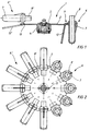
- the rotor 1 according to Figures 1 and 2 consists essentially of a disc 2, which is preferably made of a high-strength, rustproof metal material, for. B. consists of a nickel-chromium alloy.
- the disk 2 is connected via screws 5 to a rotor head 4, which is connected to the drive shaft of a drive motor, not shown, via the fastening means shown.
- the disc 2 is provided with a central recess 3, through which parts of the rotor head 4 pass.
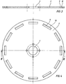
- slots 9 are worked into the disk 2 evenly distributed on the circumference of the rotor, the radially outer edges 10 of the slots 9 preferably being machined, for example having a round profile, around a pivot bearing for the swinging-out carrier parts 11 of the pivot cups 6 form.
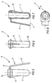
- Each swivel cup 6 consists of a sleeve 7, which preferably consists of a plastic material, in the upper, collar-shaped, enlarged edge of which the carrier part 11 is embedded.
- the carrier part 11 consists of a ring 14 made of a high-strength metal material, on which a part 13 is integrally formed, which merges into a leg 12 bent downwards over a bending edge.
- the parts 12, 13, 14 preferably consist of a material which is integrally connected to one another.
- a rib 15 is formed on the side of the sleeve 7 opposite the leg 12 in order to ensure that the sleeve 7 is stabilized in this area.
- a sample tube 8 is placed, which receives the sample liquid.
- the sleeve 7 is adapted to the sample tube 8.
- the free end of the leg 12 is chosen so long that it forms approximately a line 17 with the bottom region of the sleeve 7, it being possible for a rib 16 to be additionally formed on the bottom region of the sleeve.
- the leg 12 serves as a support foot for the swivel cup 6, which can thus be placed freely on a footprint.
- the swivel cups 6 pivot outwards, as shown in FIG. 1, 2 on the left side.
- the edges 10 of the slots 9 serve as pivot bearings and the swinging out takes place in the transition region between the straight part 13 and the leg 12 of the carrier part 11 bent downwards.
- the carrier part 11 transmits the centrifugal force to the slot 9 via the edge 10 to the disk 2 in a load-transmitting manner.
- the rotor can thus be of the simplest design and no complex contact surfaces on the rotor are required to absorb centrifugal forces.
- FIG. 12 shows a further rotor 20 which holds swivel cups 6 which are connected to differently designed carrier parts 21.
- Each carrier part here has a leg 22 which is bent approximately in a Z-shape and which, in the rest position of the swivel cup 6, rests with its end edge 23 on the rotor head 4. In this way, in the rest position of the rotor, a certain, desired and adjustable by the shape of the legs 22 inclined position of the swivel cup is achieved.
- a swivel position can also be set arbitrarily by shaping the legs 22 when the swivel cup is swung out. In this case, the end edge 23 of the leg 22 then strikes (not shown) on the associated stop surfaces of the rotor.
Landscapes
- Centrifugal Separators (AREA)
Abstract
Description
Die Erfindung betrifft einen Rotor für eine Schwenkbecherzentrifuge nach dem Oberbegriff des Patentanspruchs 1.The invention relates to a rotor for a swivel cup centrifuge according to the preamble of patent claim 1.
Ein derartiger Rotor ist mit dem auf den gleichen Anmelder Zurückgehenden DE 89 03 511 U1 bekannt geworden. Bei diesem Rotor sind die Schwenkbecher als Probenröhrchen ausgebildet, so daß diese unmittelbar mit einer Probeflüssigkeit gefüllt sind und im übrigen aus Kunststoff bestehen. Es sind radial vordere und hintere in radialer Richtung hintereinander liegende Ausnehmungen in dem im wesentlichen als horizontale Scheibe ausgebildeten Rotor eingearbeitet, die ein Einschwenken des Schwenkbechers in diese Ausnehmungen beim Ausschwingen der Schwenkbecher ermöglichen sollen. Beim Ausschwingen legen sich die bekannten Schwenkbecher mit ihren Bodenbereichen an einem umlaufenden radial äußeren Flansch des Rotors an, wobei die als Schwenklager dienenden, henkelartigen Schenkel, die in zugeordnete Ausnehmungen der Scheibe eingreifen, nicht lastübertragend mehr wirken sollen. Es handelt sich also um Schwenklager, die lediglich der Lagensicherung und der Drehsicherung der ausschwingenden Schwenkbecher dienen und die mindestens bei Erreichen der Solldrehzahl keine weitere Zentrifugalkraft mehr übertragen sollen, weil diese über den Bodenbereich des Schwenkbechers auf den radial außen liegenden, umlaufenden Flansch des Rotors übertragen wird.Such a rotor has become known from DE 89 03 511 U1, which goes back to the same applicant. In this rotor, the swivel cups are designed as sample tubes so that they are filled directly with a sample liquid and, moreover, consist of plastic. Radially front and rear recesses lying one behind the other in the radial direction are incorporated in the rotor, which is essentially designed as a horizontal disk, and are intended to enable the swivel cup to pivot into these recesses when the swivel cup swings out. When swinging out, the known swivel cups rest with their bottom regions on a circumferential, radially outer flange of the rotor, the handle-like legs serving as swivel bearings, which engage in the associated recesses in the disk, no longer being supposed to have a load-transmitting effect. These are swivel bearings that only serve to secure the position and the rotation of the swinging out swivel cups and that should no longer transmit any centrifugal force at least when the setpoint speed is reached, because they transfer to the radially outer circumferential flange of the rotor via the bottom area of the swivel cup becomes.
Mit dem bekannten Rotor bestand also der Vorteil, daß man relativ kostengünstige Probengefäße verwenden konnte, die mit ihren henkelartigen, freien Schenkeln ohne weitere Hilfsmittel in den Rotor eingehängt werden konnten.The known rotor therefore had the advantage that relatively inexpensive sample vessels could be used, which could be hooked into the rotor with their handle-like, free legs without any additional aids.
Wegen der Notwendigkeit der Lastübertragung der auf die Schwenkbecher wirkenden Zentrifugalkraft über den radial außen liegenden Flansch des Rotors ergab sich jedoch ein erhöhter Herstellungsaufwand für den Rotor.Because of the necessity of the load transmission of the centrifugal force acting on the swivel cups via the radially outer flange of the rotor, however, there was an increased manufacturing outlay for the rotor.
Der Erfindung liegt deshalb die Aufgabe zugrunde, einen Rotor der eingangs genannten Art so weiterzubilden, daß der Rotor selbst einfach ausgebildet sein kann und trotzdem hohe Zentrifugalkräfte von den Schwenkbechern auf den Rotor übertragbar sind.The invention is therefore based on the object of developing a rotor of the type mentioned in such a way that the rotor itself can be of simple construction and nevertheless high centrifugal forces can be transmitted from the swivel cups to the rotor.
Zur Lösung der gestellten Aufgabe ist die Erfindung durch die technische Lehre des Anspruches 1 gekennzeichnet.To achieve the object, the invention is characterized by the technical teaching of claim 1.
Wesentliches Merkmal der Erfindung ist, daß nun der Rotor im wesentlichen als Scheibe ausgebildet ist, die eine Reihe in Umfangsrichtung verteilt angeordneter Schlitze trägt. Es entfällt nun die Notwendigkeit, am Außenumfang des Rotors einen lastübertragenden, radialen, abgekröpften Flansch vorzusehen, welcher die Zentrifugalkraft der Schwenkbecher aufnimmt, wie dies bei dem DE 89 03 511 U1 gefordert war.An essential feature of the invention is that the rotor is now essentially in the form of a disk which bears a series of slots distributed in the circumferential direction. There is now no need to provide a load-transmitting, radial, cranked flange on the outer circumference of the rotor, which absorbs the centrifugal force of the swivel cup, as was required in DE 89 03 511 U1.
Erfindungsgemäß wird die Zentrifugalkraft, welche auf die Schwenkbecher wird, direkt von den Schwenkbechern auf das jedem Schwenkbecher zugeordnete Trägerteil übertragen, welches Trägerteil im wesentlichen aus einem ringförmigen Metallteil besteht, welches in der Hülse des Schwenkbechers eingebettet ist, wobei an diesem Ringteil - bevorzugt werkstoffeinstückig - mindestens ein Schenkel angeformt ist, mit dem dieses Trägerteil durch den Schlitz im Rotor hindurchgreift und dort schwenkbar gelagert ist.According to the invention, the centrifugal force which is exerted on the swivel cups is transmitted directly from the swivel cups to the support part assigned to each swivel cup, which support part essentially consists of an annular metal part which is embedded in the sleeve of the swivel cup, with this ring part - preferably made of one piece of material - at least one leg is formed, with which this carrier part engages through the slot in the rotor and is pivotably mounted there.
Damit ergibt sich ein extrem einfacher Aufbau des Rotors, weil lediglich eine Scheibe mit Schlitzen vorgesehen werden muß, durch welche die einzelnen Schenkel der Trägerteile der jeweiligen Schwenkbecher hindurchgreifen.This results in an extremely simple construction of the rotor, because only a disk with slots has to be provided, through which the individual legs of the carrier parts of the respective swivel cups pass.
Die genannten Schenkel greifen also kraftschlüssig und lastübertragend in die zugeordneten Schlitze der Scheibe des Rotors ein, während dies bei der älteren Druckschrift vermieden werden sollte.The legs mentioned thus engage in a force-locking and load-transmitting manner in the associated slots in the rotor disk, while this should be avoided in the older publication.
Die Schenkel sind bevorzugt schräg gestellt und sind so dimensioniert (Länge, Breite und Dicke, sowie Winkelstellung zur Längsachse der Hülse des Schwenkbechers), daß sich in einem ersten bevorzugten Ausführungsbeispiel ein annähernder Gewichtsausgleich für den Schwenkbecher bei Erreichen der Solldrehzahl des Rotors ergibt. Das heißt, die vom Schenkel ausgeübte Zentrifugalkraft und die von der Hülse des Schwenkbechers auf den Schlitz des Rotors ausgeübte Zentrifugalkraft soll bei Erreichen der Solldrehzahl der Zentrifuge etwa gleich sein, so daß sich der Schwenkbecher in einer horizontalen Schwenklage einstellt.The legs are preferably inclined and are dimensioned (length, width and thickness, as well as angular position to the longitudinal axis of the sleeve of the swivel cup), that in a first preferred embodiment there is an approximate weight compensation for the swivel cup when the target speed of the rotor is reached. This means that the centrifugal force exerted by the leg and the centrifugal force exerted by the sleeve of the swivel cup on the slot of the rotor should be approximately the same when the desired speed of the centrifuge is reached, so that the swivel cup is set in a horizontal swivel position.
In einem zweiten Ausführungsbeispiel ist es vorgesehen, daß ein beabsichtigtes Ungleichgewicht zwischen der vom Schenkel auf den Schlitz ausgeübten Zentrifugalkraft im Vergleich zu der von der Hülse auf den Schlitz ausgeübten Zentrifugalkraft ergibt, so daß eine beabsichtigte Schrägstellung des gesamten Schwenkbechers bei Erreichen der Solldrehzahl des Rotors gegeben ist.In a second embodiment it is provided that there is an intended imbalance between the centrifugal force exerted by the leg on the slot in comparison with the centrifugal force exerted by the sleeve on the slot, so that there is an intended inclination of the entire swivel cup when the target speed of the rotor is reached is.
In einem Ausführungsbeispiel ist die Länge des Schenkels so gewählt, daß das freie untere Ende des Schenkels etwa mit dem Bodenbereich der Hülse des Schwenkbechers abschließt, so daß der Schwenkbecher frei auf einer Aufstellebene aufgestellt werden kann und der Schenkel somit als Stützfuß dient.In one embodiment, the length of the leg is chosen so that the free lower end of the leg approximately ends with the bottom region of the sleeve of the swivel cup, so that the swivel cup can be set up freely on an installation level and the leg thus serves as a supporting foot.
In einer anderen Ausgestaltung ist es vorgesehen, daß der Schenkel abgekröpft ausgebildet ist, wobei bevorzugt eine etwa Z-förmige Formgebung bevorzugt wird, so daß sich das freie, abgekröpfte Ende des Schenkels bei ausschwingendem Schwenkbecher an bestimmten Anschlagflächen des scheibenförmigen Rotors anlegt.In another embodiment it is provided that the leg is bent, preferably an approximately Z-shaped shape is preferred, so that the free, bent end of the leg rests on certain stop surfaces of the disk-shaped rotor when the swivel cup swings out.
Damit kann die Winkellage des ausschwingenden Schwenkbechers begrenzt werden.This allows the angular position of the swinging swing cup to be limited.
In einer anderen Ausgestaltung der Erfindung ist es vorgesehen, daß der Schenkel so abgekröpft ist, daß sich in der Ruhelage des Gehänges, d.h. bei stillstehendem Rotor, sich das freie äußere Ende des Schenkels an dem Rotorkopf anlegt, um so die Schwenkstellung des Schwenkbechers bei stillstehendem Rotor zu definieren.In another embodiment of the invention it is provided that the leg is bent so that in the rest position of the hanger, i.e. when the rotor is at a standstill, the free outer end of the leg bears against the rotor head so as to define the pivoting position of the swivel cup when the rotor is at a standstill.
Der Erfindungsgegenstand der vorliegenden Erfindung ergibt sich nicht nur aus dem Gegenstand der einzelnen Patentansprüche, sondern auch aus der Kombination der einzelnen Patentansprüche untereinander. Alle in den Unterlagen, einschließlich der Zusammenfassung, offenbarten Angaben und Merkmale, insbesondere die in den Zeichnungen dargestellte räumliche Ausbildung werden als erfindungswesentlich beansprucht, soweit sie einzeln oder in Kombination gegenüber dem Stand der Technik neu sind.The subject matter of the present invention results not only from the subject matter of the individual patent claims, but also from the combination of the individual patent claims with one another. All information and features disclosed in the documents, including the summary, in particular the spatial design shown in the drawings are claimed as essential to the invention, insofar as they are new to the prior art, individually or in combination.
Im folgenden wird die Erfindung anhand von lediglich einen Ausführungsweg darstellenden Zeichnungen näher erläutert.In the following the invention is based on only one Execution path illustrating drawings explained in more detail.
Hierbei gehen aus den Zeichnungen und ihrer Beschreibung weitere erfindungswesentliche Merkmale und Vorteile der Erfindung hervor.Here, from the drawings and their description, further features and advantages of the invention that are essential to the invention emerge.
Es zeigen:
- Figur 1:
- einen Schnitt durch einen Rotor in Arbeits- und Ruhestellung;
- Figur 2:
- Draufsicht auf die Anordnung nach Figur 1;
- Figur 3:
- Schnitt durch die Rotorscheibe;
- Figur 4:
- Draufsicht auf die Rotorscheibe;
- Figur 5:
- Seitenansicht eines ersten Ausführungsbeispiels eines Schwenkbechers;
- Figur 6:
- die um 90° gedrehte Seitenansicht;
- Figur 7:
- Schnitt durch den Schwenkbecher nach
Figur 5; - Figur 8:
- Draufsicht auf den Schwenkbecher nach
Figur 5; - Figur 9:
- Schnitt durch das Trägerteil;
- Figur 10:
- Draufsicht auf das Trägerteil;
- Figur 11:
- das Trägerteil in Draufsicht vor Anbringung einer Biegung;
- Figur 12:
- Schnitt durch eine zweite Ausführungsform eines Rotors.
- Figure 1:
- a section through a rotor in the working and rest position;
- Figure 2:
- Top view of the arrangement according to Figure 1;
- Figure 3:
- Section through the rotor disc;
- Figure 4:
- Top view of the rotor disc;
- Figure 5:
- Side view of a first embodiment of a swivel cup;
- Figure 6:
- the side view rotated by 90 °;
- Figure 7:
- Section through the swivel cup according to Figure 5;
- Figure 8:
- Top view of the swivel cup according to Figure 5;
- Figure 9:
- Section through the support part;
- Figure 10:
- Top view of the carrier part;
- Figure 11:
- the carrier part in plan view before making a bend;
- Figure 12:
- Section through a second embodiment of a rotor.
Der Rotor 1 nach Figur 1 und 2 besteht im wesentlichen aus einer Scheibe 2, die bevorzugt aus einem hochfesten, nicht rostenden Metallmaterial, z. B. einer Nickel-Chrom-Legierung besteht.The rotor 1 according to Figures 1 and 2 consists essentially of a
In an sich bekannter Weise ist die Scheibe 2 über Schrauben 5 mit einem Rotorkopf 4 verbunden, der über die dargestellten Befestigungsmittel mit der Antriebswelle eines nicht näher dargestellten Antriebsmotors verbunden ist.In a manner known per se, the
Im übrigen ist die Scheibe 2 mit einer mittleren Ausnehmung 3 versehen, durch welche Teile des Rotorkopfes 4 hindurchgreifen.In addition, the
Gemäß den Figuren 3 und 4 sind gleichmäßig verteilt am Umfang des Rotors Schlitze 9 in die Scheibe 2 eingearbeitet, wobei bevorzugt die radial außen liegenden Kanten 10 der Schlitze 9 bearbeitet sind, etwa rundprofiliert ausgebildet sind, um ein Schwenklager für die ausschwingenden Trägerteile 11 der Schwenkbecher 6 zu bilden.According to FIGS. 3 and 4,
Jeder Schwenkbecher 6 besteht aus einer Hülse 7, die bevorzugt aus einem Kunststoffmaterial besteht, in deren oberen, kragenförmig erweiterten Rand das Trägerteil 11 eingebettet ist. Das Trägerteil 11 besteht aus einem Ring 14 aus einem hochfesten Metallmaterial, an dem werkstoffeinstückig ein Teil 13 angeformt ist, welches in einen nach unten abgebogenen Schenkel 12 über eine Biegekante übergeht.Each
Die Teile 12,13,14 bestehen bevorzugt aus einem werkstoffeinstückig miteinander verbundenen Material.The
An der dem Schenkel 12 gegenüberliegenden Seite der Hülse 7 ist eine Rippe 15 angeformt, um eine Stabilisierung der Hülse 7 in diesem Bereich zu gewährleisten.A
In die Hülse 7 wird ein Probenröhrchen 8 eingestellt, welches die Probenflüssigkeit aufnimmt.In the
Je nach der Dimensionierung des Probenröhrchens (Füllvolumen, Länge, Durchmesser usw.) ist die Hülse 7 dem Probenröhrchen 8 angepaßt.Depending on the dimensioning of the sample tube (filling volume, length, diameter, etc.), the
In einem bevorzugten Ausführungsbeispiel gemäß den Figuren 5 bis 7 ist das freie Ende des Schenkels 12 so lang gewählt, daß es etwa eine Linie 17 mit dem Bodenbereich der Hülse 7 bildet, wobei am Bodenbereich der Hülse noch zusätzlich eine Rippe 16 angeformt sein kann. Auf diese Weise dient der Schenkel 12 als Stützfuß für den Schwenkbecher 6, der damit frei auf einer Aufstellfläche aufgestellt werden kann.In a preferred exemplary embodiment according to FIGS. 5 to 7, the free end of the
Im Ruhezustand des Rotors 1 greifen somit alle Schwenkbecher 6 mit ihren Schenkeln 12 durch die zugeordneten Schlitze 9 in der Scheibe 2 hindurch.In the idle state of the rotor 1, all
Bei Erreichen der Nenndrehzahl des Rotors verschwenken die Schwenkbecher 6 nach außen, wie dies in Figur 1,2 auf der linken Seite dargestellt ist. Hierbei dienen die Kanten 10 der Schlitze 9 als Schwenklager und das Ausschwingen erfolgt im Übergangsbereich zwischen dem geraden Teil 13 und dem nach unten abgebogenen Schenkel 12 des Trägerteils 11.When the nominal speed of the rotor is reached, the swivel cups 6 pivot outwards, as shown in FIG. 1, 2 on the left side. Here, the
Bei der Erfindung ist demzufolge wichtig, daß das Trägerteil 11 lastübertragend die Zentrifugalkraft auf den Schlitz 9 über die Kante 10 auf die Scheibe 2 überträgt. Der Rotor kann somit einfachst ausgebildet sein und es bedarf keiner aufwendigen Anlageflächen am Rotor, um Zentrifugalkräfte aufzunehmen.It is therefore important in the invention that the
In Figur 12 ist ein weiterer Rotor 20 dargestellt, der Schwenkbecher 6 hält, die mit anders ausgebildeten Trägerteilen 21 verbunden sind. Jedes Trägerteil weist hierbei einen Schenkel 22 auf, der etwa Z-förmig abgekröpft ist und der sich in der Ruhelage des Schwenkbechers 6 mit seiner Stirnkante 23 an dem Rotorkopf 4 anlegt. Auf diese Weise wird in der Ruhestellung des Rotors eine bestimmte, gewünschte und durch die Formgebung der Schenkel 22 einstellbare Schräglage der Schwenkbecher erreicht.FIG. 12 shows a
Umgekehrt kann auch eine Schwenklage willkürlich durch Formgebung der Schenkel 22 bei ausgeschwungenem Schwenkbecher eingestellt werden. Hierbei schlägt dann (nicht dargestellt) die Stirnkante 23 des Schenkels 22 an zugeordneten Anschlagflächen des Rotors an.Conversely, a swivel position can also be set arbitrarily by shaping the
- 11
- Rotorrotor
- 22nd
- Scheibedisc
- 33rd
- AusnehmungRecess
- 44th
- RotorkopfRotor head
- 55
- Schraubescrew
- 66
- SchwenkbecherSwivel cup
- 77
- HülseSleeve
- 88th
- ProbenröhrchenSample tube
- 99
- Schlitzslot
- 1010th
- KanteEdge
- 1111
- TrägerteilCarrier part
- 1212th
- Schenkelleg
- 1313
- Teilpart
- 1414
- Ringring
- 1515
- Ripperib
- 1616
- Ripperib
- 1717th
- Linieline
- 2020th
- Rotorrotor
- 2121
- TrägerteilCarrier part
- 2222
- Schenkelleg
- 2323
- StirnkanteFront edge
Claims (11)
Applications Claiming Priority (2)
| Application Number | Priority Date | Filing Date | Title |
|---|---|---|---|
| DE4305581A DE4305581A1 (en) | 1993-02-24 | 1993-02-24 | Rotor for a swivel cup centrifuge |
| DE4305581 | 1993-02-24 |
Publications (2)
| Publication Number | Publication Date |
|---|---|
| EP0612565A1 true EP0612565A1 (en) | 1994-08-31 |
| EP0612565B1 EP0612565B1 (en) | 1997-04-09 |
Family
ID=6481162
Family Applications (1)
| Application Number | Title | Priority Date | Filing Date |
|---|---|---|---|
| EP94101355A Expired - Lifetime EP0612565B1 (en) | 1993-02-24 | 1994-01-29 | Swinging bucket centrifuge rotor |
Country Status (3)
| Country | Link |
|---|---|
| US (1) | US5456652A (en) |
| EP (1) | EP0612565B1 (en) |
| DE (2) | DE4305581A1 (en) |
Cited By (1)
| Publication number | Priority date | Publication date | Assignee | Title |
|---|---|---|---|---|
| DE102008042971A1 (en) | 2008-10-20 | 2010-04-22 | Agilent Technologies Inc., Santa Clara | Centrifuge for use in e.g. industry for separation of components of liquids from magnetizable particles, has magnet device arranged and designed such that magnetic force acts on lower area of container for holding particles |
Families Citing this family (17)
| Publication number | Priority date | Publication date | Assignee | Title |
|---|---|---|---|---|
| US5588946A (en) * | 1994-06-24 | 1996-12-31 | Johnson & Johnson Clinical Diagnostics, Inc. | Centrifuge and phase separation |
| US6001310A (en) * | 1996-10-11 | 1999-12-14 | Shaffer; John V. | Pliable centrifuge tube array |
| US6234948B1 (en) * | 1997-10-27 | 2001-05-22 | Michael Yavilevich | Combined centrifugation assembly |
| US6579217B1 (en) * | 1999-02-11 | 2003-06-17 | Seward Ltd. | Centrifuge rotors including displacement control |
| JP4099961B2 (en) * | 2001-07-19 | 2008-06-11 | 日立工機株式会社 | Swing rotor for centrifuge and centrifuge |
| DE10316598B4 (en) * | 2003-04-11 | 2008-05-21 | Andreas Hettich Gmbh & Co. Kg | Process and centrifuge for the recovery of biological fluids |
| BR122020017678B1 (en) | 2007-10-02 | 2021-08-03 | Labrador Diagnostics Llc | SYSTEM FOR AUTOMATIC DETECTION OF AN ANALYTE IN A BODY FLUID SAMPLE |
| EP2666008B1 (en) | 2011-01-21 | 2021-08-11 | Labrador Diagnostics LLC | Systems and methods for sample use maximization |
| US20140170735A1 (en) | 2011-09-25 | 2014-06-19 | Elizabeth A. Holmes | Systems and methods for multi-analysis |
| US8475739B2 (en) | 2011-09-25 | 2013-07-02 | Theranos, Inc. | Systems and methods for fluid handling |
| US9664702B2 (en) | 2011-09-25 | 2017-05-30 | Theranos, Inc. | Fluid handling apparatus and configurations |
| US9632102B2 (en) | 2011-09-25 | 2017-04-25 | Theranos, Inc. | Systems and methods for multi-purpose analysis |
| US10012664B2 (en) | 2011-09-25 | 2018-07-03 | Theranos Ip Company, Llc | Systems and methods for fluid and component handling |
| US9810704B2 (en) | 2013-02-18 | 2017-11-07 | Theranos, Inc. | Systems and methods for multi-analysis |
| US11545241B1 (en) | 2013-09-07 | 2023-01-03 | Labrador Diagnostics Llc | Systems and methods for analyte testing and data management |
| CN104056733B (en) * | 2014-06-10 | 2017-06-13 | 苏州培英实验设备有限公司 | Self-closing presses centrifuge rotating disk |
| WO2016037051A1 (en) | 2014-09-04 | 2016-03-10 | Theranos, Inc. | Pathogen and antimicrobial resistance testing |
Citations (8)
| Publication number | Priority date | Publication date | Assignee | Title |
|---|---|---|---|---|
| DE643836C (en) * | 1933-07-13 | 1937-04-17 | Collatz & Co E | centrifuge |
| DE894010C (en) * | 1951-03-30 | 1953-10-22 | Paul Funke & Co | Centrifuge for butyrometer |
| US3420437A (en) * | 1967-02-15 | 1969-01-07 | Sorvall Inc Ivan | Cell washing centrifuge |
| FR2107154A5 (en) * | 1970-09-08 | 1972-05-05 | Technicon Instr | |
| DE2910868A1 (en) * | 1979-03-20 | 1980-10-09 | Heraeus Christ Gmbh | Laboratory centrifuge for large number of samples - has plastic holders for samples which are mounted in tilting holders on centrifuge arms |
| EP0088425A2 (en) * | 1982-03-10 | 1983-09-14 | E.I. Du Pont De Nemours And Company | A cell washing apparatus having radially inwardly directed retaining arms |
| SU1080877A1 (en) * | 1982-01-14 | 1984-03-23 | Московский технологический институт мясной и молочной промышленности | Centrifuge (its versions) |
| DE8903511U1 (en) * | 1989-03-21 | 1990-01-11 | Fa. Andreas Hettich, 7200 Tuttlingen | Centrifuge rotor with insert tube |
Family Cites Families (8)
| Publication number | Priority date | Publication date | Assignee | Title |
|---|---|---|---|---|
| US486390A (en) * | 1892-11-15 | Centrifugal cream-tester | ||
| US484685A (en) * | 1892-10-18 | Centrifugal milk-tester | ||
| US3680967A (en) * | 1970-09-14 | 1972-08-01 | Technicon Instr | Self-locating sample receptacle having integral identification label |
| US3781120A (en) * | 1970-09-14 | 1973-12-25 | Technicon Instr | Self-locating sample receptacle having integral identification label |
| US3877634A (en) * | 1973-05-25 | 1975-04-15 | Du Pont | Cell washing centrifuge apparatus and system |
| DE2938317C2 (en) * | 1979-09-21 | 1983-04-28 | Fa. Andreas Hettich, 7200 Tuttlingen | Centrifuge cups made of plastic material |
| DE3118367C2 (en) * | 1979-09-21 | 1984-05-24 | Fa. Andreas Hettich, 7200 Tuttlingen | Centrifuge cups made of plastic material |
| US4589864A (en) * | 1984-11-05 | 1986-05-20 | E. I. Du Pont De Nemours And Company | Centrifuge rotor having a resilient trunnion |
-
1993
- 1993-02-24 DE DE4305581A patent/DE4305581A1/en not_active Ceased
-
1994
- 1994-01-29 EP EP94101355A patent/EP0612565B1/en not_active Expired - Lifetime
- 1994-01-29 DE DE59402331T patent/DE59402331D1/en not_active Expired - Lifetime
- 1994-02-22 US US08/200,283 patent/US5456652A/en not_active Expired - Lifetime
Patent Citations (8)
| Publication number | Priority date | Publication date | Assignee | Title |
|---|---|---|---|---|
| DE643836C (en) * | 1933-07-13 | 1937-04-17 | Collatz & Co E | centrifuge |
| DE894010C (en) * | 1951-03-30 | 1953-10-22 | Paul Funke & Co | Centrifuge for butyrometer |
| US3420437A (en) * | 1967-02-15 | 1969-01-07 | Sorvall Inc Ivan | Cell washing centrifuge |
| FR2107154A5 (en) * | 1970-09-08 | 1972-05-05 | Technicon Instr | |
| DE2910868A1 (en) * | 1979-03-20 | 1980-10-09 | Heraeus Christ Gmbh | Laboratory centrifuge for large number of samples - has plastic holders for samples which are mounted in tilting holders on centrifuge arms |
| SU1080877A1 (en) * | 1982-01-14 | 1984-03-23 | Московский технологический институт мясной и молочной промышленности | Centrifuge (its versions) |
| EP0088425A2 (en) * | 1982-03-10 | 1983-09-14 | E.I. Du Pont De Nemours And Company | A cell washing apparatus having radially inwardly directed retaining arms |
| DE8903511U1 (en) * | 1989-03-21 | 1990-01-11 | Fa. Andreas Hettich, 7200 Tuttlingen | Centrifuge rotor with insert tube |
Non-Patent Citations (1)
| Title |
|---|
| SOVIET INVENTIONS ILLUSTRATED Section Ch Week 8445, 19 December 1984 Derwent World Patents Index; Class J04, AN 84-281344 * |
Cited By (1)
| Publication number | Priority date | Publication date | Assignee | Title |
|---|---|---|---|---|
| DE102008042971A1 (en) | 2008-10-20 | 2010-04-22 | Agilent Technologies Inc., Santa Clara | Centrifuge for use in e.g. industry for separation of components of liquids from magnetizable particles, has magnet device arranged and designed such that magnetic force acts on lower area of container for holding particles |
Also Published As
| Publication number | Publication date |
|---|---|
| DE59402331D1 (en) | 1997-05-15 |
| DE4305581A1 (en) | 1994-08-25 |
| EP0612565B1 (en) | 1997-04-09 |
| US5456652A (en) | 1995-10-10 |
Similar Documents
| Publication | Publication Date | Title |
|---|---|---|
| EP0612565B1 (en) | Swinging bucket centrifuge rotor | |
| DE3153605C2 (en) | ||
| WO2010076120A1 (en) | Mixer having rotating mixing container | |
| DE10239366A1 (en) | Wind turbine | |
| DE202007007970U1 (en) | Support frame for supporting flat solar panels, has support construction with support part at upper rod end, support bar forming support for center rear-sided area of panel holders, and other bars that are provided for supporting holders | |
| EP0727188A1 (en) | Connection system for pedicle screws | |
| DE10329959A1 (en) | Holder for a beverage container | |
| DE19606254A1 (en) | Device for compensating changes in length | |
| DE2302102A1 (en) | ROTOR FOR A CENTRIFUGE | |
| EP3110557B1 (en) | Centrifuge | |
| DE2515900A1 (en) | IMPELLER FOR AN AXIAL FAN | |
| DE3615058A1 (en) | DRIVE TRANSMISSION FOR MOWING KNIVES OF HARVESTING MACHINES | |
| DE7507237U (en) | Rotary harrow | |
| DE102006044222A1 (en) | Wind power machine, has partial rotors arranged at distance to each other, where partial rotors are provided with two lift-wing bodies that are supported between two flat support arrangements with their ends | |
| DE2529176A1 (en) | SOIL TILLING MACHINE | |
| DE69908873T2 (en) | ROTOR BLADE, IN PARTICULAR FOR A REAR ROTOR OF A HELICOPTER | |
| EP0487915B1 (en) | Angled rotor head for centrifuges | |
| DE2530105A1 (en) | SOIL TILLING MACHINE | |
| EP0842627B1 (en) | Mixing, kneeding or cutting tool for a kitchen appliance | |
| DE3540666C2 (en) | Device for the vertical alignment of the vertical axis of a structure connected to a base frame so that it can be rotated and tilted | |
| EP0272385A1 (en) | Disc mower | |
| DE2702961C2 (en) | ||
| DE102005046043B4 (en) | Mounting arrangement of a knife blade on a mixing screw of a feed mixer wagon | |
| EP1431604A1 (en) | Universal joint with retainer element. | |
| EP3812601B1 (en) | Shaped part, securing device with the shaped part, agricultural work machine with the securing device and method for mounting the securing device |
Legal Events
| Date | Code | Title | Description |
|---|---|---|---|
| PUAI | Public reference made under article 153(3) epc to a published international application that has entered the european phase |
Free format text: ORIGINAL CODE: 0009012 |
|
| AK | Designated contracting states |
Kind code of ref document: A1 Designated state(s): DE FR GB IT |
|
| 17P | Request for examination filed |
Effective date: 19950221 |
|
| GRAG | Despatch of communication of intention to grant |
Free format text: ORIGINAL CODE: EPIDOS AGRA |
|
| GRAH | Despatch of communication of intention to grant a patent |
Free format text: ORIGINAL CODE: EPIDOS IGRA |
|
| 17Q | First examination report despatched |
Effective date: 19960912 |
|
| GRAH | Despatch of communication of intention to grant a patent |
Free format text: ORIGINAL CODE: EPIDOS IGRA |
|
| GRAA | (expected) grant |
Free format text: ORIGINAL CODE: 0009210 |
|
| AK | Designated contracting states |
Kind code of ref document: B1 Designated state(s): DE FR GB IT |
|
| REF | Corresponds to: |
Ref document number: 59402331 Country of ref document: DE Date of ref document: 19970515 |
|
| ET | Fr: translation filed | ||
| GBT | Gb: translation of ep patent filed (gb section 77(6)(a)/1977) |
Effective date: 19970627 |
|
| PLBE | No opposition filed within time limit |
Free format text: ORIGINAL CODE: 0009261 |
|
| STAA | Information on the status of an ep patent application or granted ep patent |
Free format text: STATUS: NO OPPOSITION FILED WITHIN TIME LIMIT |
|
| 26N | No opposition filed | ||
| REG | Reference to a national code |
Ref country code: GB Ref legal event code: IF02 |
|
| PG25 | Lapsed in a contracting state [announced via postgrant information from national office to epo] |
Ref country code: IT Free format text: LAPSE BECAUSE OF NON-PAYMENT OF DUE FEES;WARNING: LAPSES OF ITALIAN PATENTS WITH EFFECTIVE DATE BEFORE 2007 MAY HAVE OCCURRED AT ANY TIME BEFORE 2007. THE CORRECT EFFECTIVE DATE MAY BE DIFFERENT FROM THE ONE RECORDED. Effective date: 20050129 |
|
| REG | Reference to a national code |
Ref country code: FR Ref legal event code: CD |
|
| PGRI | Patent reinstated in contracting state [announced from national office to epo] |
Ref country code: IT Effective date: 20091201 |
|
| PGFP | Annual fee paid to national office [announced via postgrant information from national office to epo] |
Ref country code: IT Payment date: 20100126 Year of fee payment: 17 |
|
| PG25 | Lapsed in a contracting state [announced via postgrant information from national office to epo] |
Ref country code: IT Free format text: LAPSE BECAUSE OF NON-PAYMENT OF DUE FEES Effective date: 20110129 |
|
| PGFP | Annual fee paid to national office [announced via postgrant information from national office to epo] |
Ref country code: DE Payment date: 20130226 Year of fee payment: 20 Ref country code: GB Payment date: 20130122 Year of fee payment: 20 Ref country code: FR Payment date: 20130207 Year of fee payment: 20 |
|
| REG | Reference to a national code |
Ref country code: DE Ref legal event code: R071 Ref document number: 59402331 Country of ref document: DE |
|
| REG | Reference to a national code |
Ref country code: GB Ref legal event code: PE20 Expiry date: 20140128 |
|
| PG25 | Lapsed in a contracting state [announced via postgrant information from national office to epo] |
Ref country code: GB Free format text: LAPSE BECAUSE OF EXPIRATION OF PROTECTION Effective date: 20140128 Ref country code: DE Free format text: LAPSE BECAUSE OF EXPIRATION OF PROTECTION Effective date: 20140130 |