EP0611447B1 - Kammer zur gefriertrocknung durch kryosorption - Google Patents
Kammer zur gefriertrocknung durch kryosorption Download PDFInfo
- Publication number
- EP0611447B1 EP0611447B1 EP93920693A EP93920693A EP0611447B1 EP 0611447 B1 EP0611447 B1 EP 0611447B1 EP 93920693 A EP93920693 A EP 93920693A EP 93920693 A EP93920693 A EP 93920693A EP 0611447 B1 EP0611447 B1 EP 0611447B1
- Authority
- EP
- European Patent Office
- Prior art keywords
- equipment according
- chamber
- vacuum
- ring
- metallic part
- Prior art date
- Legal status (The legal status is an assumption and is not a legal conclusion. Google has not performed a legal analysis and makes no representation as to the accuracy of the status listed.)
- Expired - Lifetime
Links
- 238000004108 freeze drying Methods 0.000 title claims abstract description 10
- 229910052751 metal Inorganic materials 0.000 claims abstract description 23
- 239000002184 metal Substances 0.000 claims abstract description 23
- 238000001035 drying Methods 0.000 claims abstract description 22
- IJGRMHOSHXDMSA-UHFFFAOYSA-N Atomic nitrogen Chemical compound N#N IJGRMHOSHXDMSA-UHFFFAOYSA-N 0.000 claims abstract description 11
- 239000007788 liquid Substances 0.000 claims abstract description 7
- 229910052757 nitrogen Inorganic materials 0.000 claims abstract description 5
- 239000000523 sample Substances 0.000 claims description 10
- 238000010438 heat treatment Methods 0.000 claims description 9
- 238000001816 cooling Methods 0.000 claims description 8
- 239000012520 frozen sample Substances 0.000 claims description 7
- 239000000463 material Substances 0.000 claims description 4
- 239000011521 glass Substances 0.000 claims description 2
- 239000012780 transparent material Substances 0.000 claims description 2
- 229910000831 Steel Inorganic materials 0.000 claims 3
- 239000010959 steel Substances 0.000 claims 3
- 238000013459 approach Methods 0.000 claims 1
- 230000035699 permeability Effects 0.000 claims 1
- 239000002274 desiccant Substances 0.000 abstract description 14
- 230000000295 complement effect Effects 0.000 abstract description 2
- 239000002808 molecular sieve Substances 0.000 description 8
- URGAHOPLAPQHLN-UHFFFAOYSA-N sodium aluminosilicate Chemical compound [Na+].[Al+3].[O-][Si]([O-])=O.[O-][Si]([O-])=O URGAHOPLAPQHLN-UHFFFAOYSA-N 0.000 description 8
- 238000011049 filling Methods 0.000 description 5
- 229910001220 stainless steel Inorganic materials 0.000 description 5
- 239000010935 stainless steel Substances 0.000 description 5
- XLYOFNOQVPJJNP-UHFFFAOYSA-N water Substances O XLYOFNOQVPJJNP-UHFFFAOYSA-N 0.000 description 4
- OKKJLVBELUTLKV-UHFFFAOYSA-N Methanol Chemical compound OC OKKJLVBELUTLKV-UHFFFAOYSA-N 0.000 description 3
- 238000009833 condensation Methods 0.000 description 3
- 230000005494 condensation Effects 0.000 description 3
- 238000006116 polymerization reaction Methods 0.000 description 3
- 239000007787 solid Substances 0.000 description 3
- LFQSCWFLJHTTHZ-UHFFFAOYSA-N Ethanol Chemical compound CCO LFQSCWFLJHTTHZ-UHFFFAOYSA-N 0.000 description 2
- 229910052782 aluminium Inorganic materials 0.000 description 2
- XAGFODPZIPBFFR-UHFFFAOYSA-N aluminium Chemical compound [Al] XAGFODPZIPBFFR-UHFFFAOYSA-N 0.000 description 2
- 238000013461 design Methods 0.000 description 2
- 238000009792 diffusion process Methods 0.000 description 2
- 239000007789 gas Substances 0.000 description 2
- 238000011068 loading method Methods 0.000 description 2
- 238000000034 method Methods 0.000 description 2
- 229910052756 noble gas Inorganic materials 0.000 description 2
- 150000002835 noble gases Chemical class 0.000 description 2
- 230000002035 prolonged effect Effects 0.000 description 2
- 238000004626 scanning electron microscopy Methods 0.000 description 2
- 238000007789 sealing Methods 0.000 description 2
- 229910001369 Brass Inorganic materials 0.000 description 1
- RYGMFSIKBFXOCR-UHFFFAOYSA-N Copper Chemical group [Cu] RYGMFSIKBFXOCR-UHFFFAOYSA-N 0.000 description 1
- 229910021536 Zeolite Inorganic materials 0.000 description 1
- 238000005299 abrasion Methods 0.000 description 1
- 239000012472 biological sample Substances 0.000 description 1
- 230000015572 biosynthetic process Effects 0.000 description 1
- 239000010951 brass Substances 0.000 description 1
- 239000004020 conductor Substances 0.000 description 1
- 238000010276 construction Methods 0.000 description 1
- 229910001873 dinitrogen Inorganic materials 0.000 description 1
- HNPSIPDUKPIQMN-UHFFFAOYSA-N dioxosilane;oxo(oxoalumanyloxy)alumane Chemical compound O=[Si]=O.O=[Al]O[Al]=O HNPSIPDUKPIQMN-UHFFFAOYSA-N 0.000 description 1
- 239000000428 dust Substances 0.000 description 1
- 230000000694 effects Effects 0.000 description 1
- 238000004880 explosion Methods 0.000 description 1
- 230000001744 histochemical effect Effects 0.000 description 1
- 238000005259 measurement Methods 0.000 description 1
- 238000012986 modification Methods 0.000 description 1
- 230000004048 modification Effects 0.000 description 1
- 239000002245 particle Substances 0.000 description 1
- 238000002360 preparation method Methods 0.000 description 1
- 230000002269 spontaneous effect Effects 0.000 description 1
- 238000006467 substitution reaction Methods 0.000 description 1
- 239000000725 suspension Substances 0.000 description 1
- 230000001960 triggered effect Effects 0.000 description 1
- 238000011179 visual inspection Methods 0.000 description 1
- 239000010457 zeolite Substances 0.000 description 1
Images

Classifications
-
- F—MECHANICAL ENGINEERING; LIGHTING; HEATING; WEAPONS; BLASTING
- F17—STORING OR DISTRIBUTING GASES OR LIQUIDS
- F17C—VESSELS FOR CONTAINING OR STORING COMPRESSED, LIQUEFIED OR SOLIDIFIED GASES; FIXED-CAPACITY GAS-HOLDERS; FILLING VESSELS WITH, OR DISCHARGING FROM VESSELS, COMPRESSED, LIQUEFIED, OR SOLIDIFIED GASES
- F17C3/00—Vessels not under pressure
- F17C3/02—Vessels not under pressure with provision for thermal insulation
- F17C3/08—Vessels not under pressure with provision for thermal insulation by vacuum spaces, e.g. Dewar flask
- F17C3/085—Cryostats
-
- F—MECHANICAL ENGINEERING; LIGHTING; HEATING; WEAPONS; BLASTING
- F25—REFRIGERATION OR COOLING; COMBINED HEATING AND REFRIGERATION SYSTEMS; HEAT PUMP SYSTEMS; MANUFACTURE OR STORAGE OF ICE; LIQUEFACTION SOLIDIFICATION OF GASES
- F25D—REFRIGERATORS; COLD ROOMS; ICE-BOXES; COOLING OR FREEZING APPARATUS NOT OTHERWISE PROVIDED FOR
- F25D3/00—Devices using other cold materials; Devices using cold-storage bodies
- F25D3/10—Devices using other cold materials; Devices using cold-storage bodies using liquefied gases, e.g. liquid air
-
- F—MECHANICAL ENGINEERING; LIGHTING; HEATING; WEAPONS; BLASTING
- F26—DRYING
- F26B—DRYING SOLID MATERIALS OR OBJECTS BY REMOVING LIQUID THEREFROM
- F26B5/00—Drying solid materials or objects by processes not involving the application of heat
- F26B5/04—Drying solid materials or objects by processes not involving the application of heat by evaporation or sublimation of moisture under reduced pressure, e.g. in a vacuum
- F26B5/06—Drying solid materials or objects by processes not involving the application of heat by evaporation or sublimation of moisture under reduced pressure, e.g. in a vacuum the process involving freezing
-
- G—PHYSICS
- G01—MEASURING; TESTING
- G01N—INVESTIGATING OR ANALYSING MATERIALS BY DETERMINING THEIR CHEMICAL OR PHYSICAL PROPERTIES
- G01N1/00—Sampling; Preparing specimens for investigation
- G01N1/28—Preparing specimens for investigation including physical details of (bio-)chemical methods covered elsewhere, e.g. G01N33/50, C12Q
- G01N1/42—Low-temperature sample treatment, e.g. cryofixation
Definitions
- the invention relates to a device for freeze drying by cryosorption with liquid nitrogen cooling, according to the preamble of Claim 1.
- the thermostatically heatable plate for holding the frozen samples is attached in the upper part. After filling the molecular sieve and loading the sample plate with the frozen objects, both parts are screwed together in a vacuum-tight manner. The container is then placed in an LN2-filled dewar. Since all wall surfaces of the container are now in direct contact with LN2 (temperature -196 ° C), the molecular sieve also cools down and adsorbs the majority of the gas molecules present in the container (O 2 , N 2 , CO 2 , H 2 O).
- the object of the present invention is to provide an arrangement create what the advantages of the Edelmann container without its disadvantages to its full advantage and therefore without restrictions for routine use is suitable.
- this object is achieved by designing the Edelmann concept according to the characterizing part of claim 1 solved.
- the arrangement according to the invention has cooling, which done on one side on the bottom surface of a container in a known manner so that this floor surface with a complementarily designed surface on the Corresponds to the top of an LN2-cooled solid, which is in one Dewar is located, the level of the LN2 level in the Dewar due to the material cross-section and the thermal conductivity of this Solid body has no significant influence on the temperature of the contact surface exercises, which is usually at most 20 ° C from the LN2 temperature (-196 ° C) differs.
- the bottom of the GT chamber is preferably part of one Turning piece made of a metal with good heat conduction (e.g.
- brass or Aluminum which is a chamber to hold a desiccant (e.g. molecular sieve "Zeolite") as well as a recess on the top for the Has plate for holding the frozen samples.
- a desiccant e.g. molecular sieve "Zeolite”
- the chamber for that Desiccant has at least one connection to the freeze drying chamber, if necessary, an additional vacuum-tight opening for filling and replacement of the desiccant.
- the side wall of the chamber is covered by a preferably cylindrical sleeve made of a poorly heat-conducting thin-walled metal sheet (e.g.
- the standard flange which preferably in the area of the chamber, which comes from the Dewar jar protrudes, for example on the upper end ring can be arranged and the GT chamber space with the room atmosphere connects.
- Any commercially available vacuum modules can be attached to it (e.g. vacuum meter, valves, hose connections for backing pumps etc.) be connected.
- the frozen samples can be a plate in the recess at the top of the bottom rotating piece the chamber can be provided, the one heating cartridge and one Temperature sensor for thermostatic heating and on its top has at least one trough for receiving the frozen samples.
- the This plate is preferably mounted on the rotating floor part via point or Line supports in such a way that between the frozen turned part ( ⁇ 176 ° C) and the sample plate, which is usually heated to around -80 ° C at the GT, is only a minimal thermal contact results.
- Embodiments of the inventions can consist, for example, in that additional cooling surfaces which increase the binding of H 2 O can be screwed or articulated to the bottom rotating part, and that the chamber for the permanent guarantee of thermal contact between the bottom surface of the chamber and the complementary solid surface in the chamber which cannot be influenced by manipulation forces Dewar flask is screwed to the dewar flask or a mounting part fastened to the dewar flask, a screw connection prestressed by spring elements being able to compensate changes in length of the cooled parts according to the invention.
- valves shut off the Chamber with the desiccant in the bottom part as well as opening a connection to the interior of the dewar and thus flooding the GT chamber effect dry cold nitrogen gas (henceforth "GN2")
- the first valve can simultaneously be designed as a pressure relief valve and thereby the user before spontaneous release of adsorbed gases after long Dry periods when the chamber is warmed up after the last has evaporated Protects LN2 remnants from the Dewar flask without taking any special precautions an explosion of the floor part.
- Vacuum connections as well as another valve with a downstream one Hose connection for pre-evacuating the chamber space to remove the Most of the noble gases are provided, and that the lid for Closure of the upper chamber opening from a transparent and / or UV-transparent Material exists, as well as that the upper end ring and the provided valves for the event of prolonged flooding of the chamber dry cold GN2 at least one heating cartridge and a temperature sensor have a thermostatic heating of these elements as protection against annoying cooling.
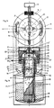
- the chamber according to the invention for GT by cryosorption according to FIGS. 1a and 1b is inserted according to the prior art into a dewar 1 with a filling of LN2 2, which contains an insert 6, for example one on a bolt 3 on the dewar bottom, and on the end ring 4 of the vessel 1 via a sleeve 5 made of thin-walled stainless steel sheet-supported aluminum cylinder 6 (material cross section> 10 cm 2 ), the preferably flat upper boundary surface 7 of which has a temperature which is largely independent of the LN2 filling level and which is at most 20 ° C. from the LN2 temperature ( -196 ° C) differs.
- the GT chamber according to the invention preferably consists of a rotating part 8, the bottom surface 25 of which corresponds complementarily to the surface 7 of the metal body 6 and has a temperature below -176 ° C. due to the good thermal contact when the vessel 1 is filled with LN2.
- the rotating part 8 is connected in a vacuum-tight manner to a preferably cylindrical sleeve 9 made of thin metal sheet with low heat conduction (for example stainless steel sheet with a thickness of 0.2 to 1 mm, height> 100 mm), the upper edge of which protrudes from the neck of the Dewar vessel 1 and is preferably connected in a vacuum-tight manner to a ring 10 made of a good heat-conducting metal.
- Valves with the control buttons 11, 12 and 13, and a vacuum connection for example a standard flange 14 for connecting a measuring tube 15 for vacuum measurement or other commercially available vacuum modules and / or a hose connection for pre-evacuating the GT chamber, can preferably be arranged on this ring 10.
- the opening of the ring 10 can be closed in a vacuum-tight manner with a cover 19 and the O-ring 18.
- a housing 21 for the UV lamp 22 with reflector 22 ' can be placed on the ring 10, for example via the intermediate element 20, which enables UV polymerization in the chamber (cf. E. Carlemalm et al, in M. Müller) et al, editor, The Science of Biological Specimen Preparation, IV, 147 ff, SEM Inc.
- the chamber 8, 9, 10, 18, 19 can be secured by an additional connection, for example a screw connection, by means of the stud bolts 23, which are anchored in the end ring 4 on the neck of the Dewar vessel 1 and for protection against the manipulation forces typical of the operation and a tilting triggered thereby if necessary, by means of a suspension (eg disc springs 24), maintain the frictional contact of the corresponding surfaces 7/25 and thus the required thermal contact even if the lengths of different components vary due to temperature fluctuations.
- an additional connection for example a screw connection
- stud bolts 23 which are anchored in the end ring 4 on the neck of the Dewar vessel 1 and for protection against the manipulation forces typical of the operation and a tilting triggered thereby if necessary
- a suspension eg disc springs 24
- a sealing ring 27 made of flexible material can prevent the entry of moist room air and one prevent the resulting frost formation in the neck of the Dewar 1.
- the GT chamber can finally be flooded with dry, cold GN2 in the manner shown (cf. FIGS. 1a, 1b and 2) in that a heating cartridge 28 from the LN2 GN2 into a bore 29 of the cylinder 6 evaporates, which communicates with a bore or a tube 52, which runs through the rotating part 8, for example.
- the rotating part 8 has a desiccant chamber 30 to hold a desiccant 31 (e.g. molecular sieve), e.g. after opening a lid 32 can be replaced, one Seal (e.g. copper ring 33) also a permanent vacuum-tight seal guaranteed at temperatures ⁇ 180 ° C.
- a desiccant 31 e.g. molecular sieve
- one Seal e.g. copper ring 33
- At the bottom of the through the surface of the parts 8,9,10,18,19 formed drying chamber 34 is in a Deepening of the rotating part 8 of the plate 35 with at least one trough 36 Recording the frozen samples 37.
- the plate 35 can be by means of a heating cartridge 38 and a temperature sensor 39 are heated thermostatically and stands with the wall of the rotating part 8 only via point contacts (e.g. tip pads 40) or line contacts (e.g. balls 41 from bad heat-conducting material, e.g. glass, which in corresponding Support holes in parts 8 and 35 rest) in contact. Larger Heat transfers between elements 8 and 35 are in this way Vacuum operation avoided.
- point contacts e.g. tip pads 40
- line contacts e.g. balls 41 from bad heat-conducting material, e.g. glass, which in corresponding Support holes in parts 8 and 35 rest
- An embodiment of the invention may consist in that to expand the Cold surfaces of the rotating part 8 additional condensation surfaces for water vapor by the springs (e.g. disc springs 42) articulated via stud bolts 43 Elements 44 are created, the contact surfaces of the corresponding parts 8 and 44 with regard to a flawless For example, the heat contact is precisely planed and if necessary with a heat-conducting liquid or paste of low vapor pressure are covered.
- the condensation elements 44 can be inserted or removed of the samples 37 either pivoted away to the side or after removal of the Stud bolts 43 are removed entirely.
- Another embodiment of the invention may be that connection 45 to a network or filter 46 to protect against the entry of dust particles (e.g.
- valve 47/48 abrasion from Molecular sieve 31
- the Valve seat 47 for example, on a vacuum-tight part with the rotating part 8 connected thin-walled stainless steel tube 49 attached and from a well thermally conductive metal part 50 may be surrounded, which is in good thermal contact with the upper end ring 10.
- the valve 47/48 is turned by turning the Button 11 opened or closed and exercises through the spring (e.g. Coil spring 51) at the same time the function of a technically known Overpressure valve, which opens in the limit position of the button 11, if in the desiccant chamber 30 in the manner already described Overpressure arises.
- a shut-off valve (control button 13 in Fig. 1) with a downstream hose connection 16 (Fig. 1) for connecting a Water jet or diaphragm pumps that do not introduce a risk that Oil deposits occur on the frozen objects, are provided and that a stainless steel tube 52 connected to the rotating part 8 in a vacuum-tight manner a further valve 53/54 is connected in a vacuum-tight manner, which is activated by the button 12 can be opened and closed, the valve seat 53 accordingly the valve seat 47 by an element 50 'thermally to the upper end ring 10 of the chamber is coupled and the valve function of this valve except for the in this case, the pressure relief valve that is not required is that of the valve Corresponds to 11/47/48/50.
- the valve 12/53/54/50 'allows the drying chamber 34 after completing the GT of samples 37 with dry cold GN2 from the Interior of the dewar in the one shown in FIG. 1 and already described Flooding, with orientation aids (e.g. bolts 55/56) required agreement of the spatial locations of the communicating Ensure tubes 29 and 52.
- orientation aids e.g. bolts 55/56
- a flanking configuration exists finally in that the upper end ring 10 by means of a heating cartridge 58th and a temperature sensor 57 can be heated thermostatically, so that at prolonged flooding of the drying chamber 34 with cold GN2 from the Dewar interior neither the valve seats 47/53, nor the upper end ring 10 in one annoying and cumbersome for further operation to be cooled.
- the GT chamber according to the invention can be designed in a corresponding modification or combination of the construction and configurations described in very different ways without thereby losing its inventive character.
- the type of cooling of the bottom surface 25 of the part 8 is irrelevant as long as this bottom surface is cooled in a technically known manner to a temperature which, after the pre-evacuation according to the invention by a desiccant 31 in a desiccant chamber 30, achieves a vacuum better than 0.133 Pa (10 -3 Torr) enables, as is required for a GT. It is also irrelevant where and how an opening for filling or removing the desiccant 31 is provided in the desiccant chamber 30.
- valves 47/48 and 53/54 which for example are also arranged directly on the rotating part 8, or whose axes are rotated, for example, 90 ° horizontally in the ring 10 instead of the manner shown in FIG. 2 can be moved vertically, so that the additional thermal connection to the upper end ring is omitted. It is irrelevant how the surface of the cold parts for water retention is increased if necessary.
- An alternative to the additional cooling elements 44 described is, for example, the pulling up of the edge 8 'of the rotary part 8, indicated in dashed lines in FIG.
Landscapes
- Engineering & Computer Science (AREA)
- Mechanical Engineering (AREA)
- Physics & Mathematics (AREA)
- General Engineering & Computer Science (AREA)
- Chemical & Material Sciences (AREA)
- Health & Medical Sciences (AREA)
- Life Sciences & Earth Sciences (AREA)
- Thermal Sciences (AREA)
- Biochemistry (AREA)
- Combustion & Propulsion (AREA)
- Analytical Chemistry (AREA)
- Molecular Biology (AREA)
- General Health & Medical Sciences (AREA)
- General Physics & Mathematics (AREA)
- Immunology (AREA)
- Pathology (AREA)
- Drying Of Solid Materials (AREA)
- Sampling And Sample Adjustment (AREA)
- Vaporization, Distillation, Condensation, Sublimation, And Cold Traps (AREA)
Description
Claims (19)
- Einrichtung zur Gefriertrocknung durch Kryosorption mit einer Kühlung durch Flüssigstickstoff (2), der sich in einem Dewargefäß (1) befindet, mit einem Trockenmittel (31) und mit einer Trockenkammer (34) zur Aufnahme einer Probe (37), wobei die Außenwandung der Trockenkammer (34) aus einer Metallwand (9) besteht und die Trockenkammer (34) über einen Ring (10) vakuumdicht verschließbar ausgebildet ist,
dadurch gekennzeichnet, daßdie Trockenkammer (34) großteils im Hals des Dewargefäß (1) angeordnet ist und der untere Rand der Metallwand (9) mit dem unteren Rand eines metallischen Teiles (8) vakuumdicht verbunden ist, und die Unterseite des metallischen Teils (8) eine Kontaktfläche (25) aufweist, die mit einem von Flüssigstickstoff umspülten und wärmeleitenden Körpers (6) verbunden ist, wobei das metallische Teil (8) durch den wärmeleitenden Körper (6) abgekühlt wird und das metallische Teil (8) eine Trockenmittelkammer (30) zur Aufnahme des Trockenmittels (31) für die Kryosorption, beispielsweise ein Molekularsieb, sowie einen, über ein Ventil (47/48) schaltbaren, Verbindungskanal (45) zu der Trockenkammer (34) aufweist,und der obere Rand der Metallwand (9) mit dem Ring (10) sich außerhalb des Dewargefäßes (1) und deshalb annähemd auf Raumtemperatur befindet. - Einrichtung nach Anspruch 1, dadurch gekennzeichnet, daß die Metallwand (9) aus einem dünnen Blech, vorzugsweise in der Stärke von 0,2 mm bis 1 mm, besteht.
- Einrichtung nach Anspruch 2, dadurch gekennzeichnet, daß das Blech ein Edelstahlblech ist.
- Einrichtung nach einem der Ansprüche 1 bis 3, dadurch gekennzeichnet, daß die Höhe der Metallwand (9) mindestens 100 mm beträgt.
- Einrichtung nach einem der Ansprüche 1 bis 4, dadurch gekennzeichnet, daß das metallische Teil (8) eine durch einen Deckel (32) vakuumdicht verschließbare Öffnung, vorzugsweise mit einer Metallringdichtung (33), zum Nachfüllen oder Austauschen von Trockenmittel (31) aufweist.
- Einrichtung nach einem der Ansprüche 1 bis 5, dadurch gekennzeichnet, daß der Ring (10) mindestens einen Vakuumanschluß (14) zum Anschluß handelsüblicher Vakuumbauteile aufweist, wobei die Öffnung an der Oberseite des Ringes (10) vorzugsweise durch einen handelsüblichen O-Ring (18) im Verein mit einem Deckel (19) vakuumdicht verschließbar ist.
- Einrichtung nach einem der Ansprüche 1 bis 6, dadurch gekennzeichnet, daß zur Aufnahme der gefrorenen Proben (37) ein Teller (35) aus gut wärmeleitendem Metall vorgesehen ist, der mittels einer Heizpatrone (38) sowie eines Temperaturfühlers (39) thermostatisch beheizbar ist und zur Aufnahme und Einbettung der Proben (37) an seiner Oberseite mindestens eine Mulde (36) aufweist und mit dem metallischen Teil (8) in einer Weise verbunden ist, daß zwischen dem Teller (35) und dem metallischen Teil (8) bei evakuierter Trockenkammer (34) ein hoher Wärmewiderstand resultiert.
- Einrichtung nach Anspruch 7, dadurch gekennzeichnet, daß die Verbindung zwischen dem metallischen Teil (8) und dem Probenteller (35) über Spitzenauflagen (40) erfolgt.
- Einrichtung nach Anspruch 7, dadurch gekennzeichnet, daß die Verbindung zwischen dem metallischen Teil (8) und dem Probenteller (35) über Kugeln geringen Wärmeleitvermögens (41), beispielsweise Glaskugeln, erfolgt, welche zu den Rändem von Aufnahmebohrungen in dem metallischen Teil (8) und dem Probenteller (35) jeweils eine Linienberührung aufweisen.
- Einrichtung nach einem der Ansprüche 1 bis 9, dadurch gekennzeichnet, daß an der Oberseite des metallischen Teils (8) Metallteile (44) mit gutem Wärmeleitvermögen und zumindest einer planen Kontaktfläche befestigbar sind, welche mit dem metallischen Teil (8) einen guten Wärmekontakt aufweisen und zum Einbringen bzw. zur Entnahme der Proben (37) aus den Mulden (36) des Probentellers (35) entweder um die Achsen der Befestigungselemente (42,43) wegschwenkbar oder nach Lösen der Befestigungselemente (42,43) entfernbar sind.
- Einrichtung nach einem der Ansprüche 1 bis 10, dadurch gekennzeichnet, daß die Trockenkammer (34) durch Befestigungselemente (23,24) so am Dewar (1) oder an einem ortsfest mit dem Dewar (1) verbundenen Montage-Element (Ring 4) befestigbar ist, daß unabhängig von betriebsüblich auftretenden Manipulationskräften stets ein kraftschlüssiger Kontakt zwischen den korrespondierenden Flächen (25) und (7) am metallischen Teil (8) sowie am Körper (6) gewährleistet ist.
- Einrichtung nach Anspruch 1, dadurch gekennzeichnet, daß sich das Ventil (47/48) in der Trockenkammer (34) befindet und sich zwischen dem Ventilsitz (47) und der Oberseite des metallischen Teils (8) im Anschluß an die Verbindung in Form eines Verbindungskanals (45) ein dünnwandiges Rohr (49) aus einem Material geringer Wärmeleitung, vorzugsweise ein Edelstahlrohr mit einer Wandstärke von weniger als 0,5 mm, befindet, und daß der Ventilsitz (47) durch einen Metallteil (50) guter Wärmeleitung mit dem Ring (10) thermisch verbunden ist.
- Einrichtung nach Anspruch 12, dadurch gekennzeichnet, daß das Ventil (47/48) durch ein Federelement (51) als Überdruckventil ausgebildet ist, das sich bei einem Überdruck in der Trockenmittelkammer (30) mit dem Trockenmittel (31) automatisch öffnet.
- Einrichtung nach einem der Ansprüche 1 bis 13, dadurch gekennzeichnet, daß ein Ventil (53/54) vorhesehen ist, das die Trockenkammer (34) über eine Rohrleitung (52,29) mit dem Innenraum des Dewargefäßes (1) verbindet.
- Einrichtung nach Anspruch 14, dadurch gekennzeichnet, daß der in der Trockenkammer (34) verlaufende Abschnitt (52) der Rohrleitung aus einem dünnwandigen Rohr geringer Wärmeleitung, vorzugsweise aus einem Edelstahlrohr mit Wandstärke von weniger als 0,5 mm, besteht, das mit dem metallischen Teil (8) vakuumdicht verbunden ist, und daß der Ventilsitz (53) durch einen Metallteil (50') guter Wärmeleitung mit dem Ring (10) thermisch verbunden ist.
- Einrichtung nach einem der Ansprüche 1 bis 15, dadurch gekennzeichnet, daß der Abschlußdeckel (19) aus einem durchsichtigen Material besteht.
- Einrichtung nach einem der Ansprüche 1 bis 16, dadurch gekennzeichnet, daß der Abschlußdeckel (19) eine hohe Durchlässigkeit für UV-Strahlen aufweist.
- Einrichtung nach einem der Ansprüche 1 bis 17, dadurch gekennzeichnet, daß auf den Ring (10) ein UV-Strahler (20 bis 22, 22') aufsetzbar ist.
- Einrichtung nach einem der Ansprüche 1 bis 18, dadurch gekennzeichnet, daß der Ring (10) mittels einer Heizpatrone (58) und eines Temperatursensors (57) thermostatisch beheizbar ausgebildet ist.
Applications Claiming Priority (3)
| Application Number | Priority Date | Filing Date | Title |
|---|---|---|---|
| AT0178892A AT398849B (de) | 1992-09-08 | 1992-09-08 | Kammer zur gefriertrocknung durch kryosorption |
| AT1788/92 | 1992-09-08 | ||
| PCT/EP1993/002409 WO1994005996A1 (de) | 1992-09-08 | 1993-09-06 | Kammer zur gefriertrocknung durch kryosorption |
Publications (2)
| Publication Number | Publication Date |
|---|---|
| EP0611447A1 EP0611447A1 (de) | 1994-08-24 |
| EP0611447B1 true EP0611447B1 (de) | 1998-04-29 |
Family
ID=3520992
Family Applications (1)
| Application Number | Title | Priority Date | Filing Date |
|---|---|---|---|
| EP93920693A Expired - Lifetime EP0611447B1 (de) | 1992-09-08 | 1993-09-06 | Kammer zur gefriertrocknung durch kryosorption |
Country Status (6)
| Country | Link |
|---|---|
| US (1) | US5438838A (de) |
| EP (1) | EP0611447B1 (de) |
| JP (1) | JPH07500919A (de) |
| AT (2) | AT398849B (de) |
| DE (1) | DE59308470D1 (de) |
| WO (1) | WO1994005996A1 (de) |
Cited By (2)
| Publication number | Priority date | Publication date | Assignee | Title |
|---|---|---|---|---|
| DE102004046762A1 (de) * | 2004-09-24 | 2006-04-06 | Leica Mikrosysteme Gmbh | Vorrichtung zur Polymerisation von biologischen Proben bei der Gefriersubstitution und Verwendung von Dioden mit UV-Anteilen |
| DE102005003286A1 (de) * | 2005-01-25 | 2006-07-27 | Leica Mikrosysteme Gmbh | Behälter für eine Vorrichtung zur automatisierten Gefrier- oder Tieftemperatursubstitution |
Families Citing this family (6)
| Publication number | Priority date | Publication date | Assignee | Title |
|---|---|---|---|---|
| DE60120346T2 (de) * | 2001-03-01 | 2007-05-16 | Incorporated Administrative Agency National Agriculture And Bio-Oriented Research Organization, Tsukuba | Verfahren und Vorrichtung zur Herstellung eines gefriergetrockneten Produktes |
| US6543155B2 (en) * | 2001-03-01 | 2003-04-08 | National Agricultural Research Organization | Freeze-dried product and process and apparatus for producing it |
| JP5584153B2 (ja) * | 2011-02-28 | 2014-09-03 | 大陽日酸株式会社 | 予備凍結器 |
| ES2542107B1 (es) * | 2013-12-30 | 2016-05-12 | Universidad De Zaragoza | Liofilizador para laboratorio |
| CN109060495B (zh) * | 2018-09-11 | 2024-03-15 | 四川省机械研究设计院(集团)有限公司 | 可调节热阻的装置 |
| US11054185B1 (en) * | 2020-02-24 | 2021-07-06 | Lyophilization Technology, Inc. | Apparatus for lyophilization of products contained in product delivery units |
Family Cites Families (12)
| Publication number | Priority date | Publication date | Assignee | Title |
|---|---|---|---|---|
| US2465229A (en) * | 1944-09-07 | 1949-03-22 | Westinghouse Electric Corp | Vacuum trap |
| US3009258A (en) * | 1958-04-24 | 1961-11-21 | Fisher Scientific Co | Histological manifolds |
| US3216207A (en) * | 1962-10-15 | 1965-11-09 | Continental Oil Co | Cold trap assembly for high vacuum systems |
| US3330125A (en) * | 1963-02-07 | 1967-07-11 | Klipping Gustav | Cryogenic method |
| US3309844A (en) * | 1963-11-29 | 1967-03-21 | Union Carbide Corp | Process for adsorbing gases |
| FR2048253A5 (de) * | 1969-12-01 | 1971-03-19 | Air Liquide | |
| DE2739796A1 (de) * | 1977-09-03 | 1979-03-15 | Reichert Optische Werke Ag | Einrichtung zur gefriertrocknung und gegebenenfalls kunstharz-impraegnation kleiner biologischer objekte fuer die elektronenmikroskopische untersuchung |
| US4232453A (en) * | 1978-09-25 | 1980-11-11 | C. Reichert Optische Werke, Ag | Device for freeze drying and synthetic resin impregnation when necessary of small biological objects for electron microscopic examination |
| DE2944464A1 (de) * | 1979-11-03 | 1981-05-14 | C. Reichert Optische Werke Ag, Wien | Einrichtung zur kryosubstitution kleiner biologischer objekte fuer mikroskopische, insbesondere elektronenmikroskopische untersuchungen |
| US4799361A (en) * | 1983-08-23 | 1989-01-24 | Board Of Regents, The University Of Texas System | Method for cryopreparing biological tissue for ultrastructural analysis |
| SU1698482A1 (ru) * | 1988-01-08 | 1991-12-15 | Институт Анатилического Приборостроения Научно-Технического Объединения Ан Ссср | Криогенный конденсационный насос |
| SU1682628A1 (ru) * | 1988-03-10 | 1991-10-07 | Институт Аналитического Приборостроения Научно-Технического Объединения Ан Ссср | Криоадсорбционный насос |
-
1992
- 1992-09-08 AT AT0178892A patent/AT398849B/de not_active IP Right Cessation
-
1993
- 1993-09-06 JP JP6506891A patent/JPH07500919A/ja active Pending
- 1993-09-06 US US08/232,151 patent/US5438838A/en not_active Expired - Fee Related
- 1993-09-06 DE DE59308470T patent/DE59308470D1/de not_active Expired - Fee Related
- 1993-09-06 WO PCT/EP1993/002409 patent/WO1994005996A1/de not_active Ceased
- 1993-09-06 AT AT93920693T patent/ATE165664T1/de not_active IP Right Cessation
- 1993-09-06 EP EP93920693A patent/EP0611447B1/de not_active Expired - Lifetime
Non-Patent Citations (1)
| Title |
|---|
| GIT LABOR-MEDIZIN, Nr.5, 1087, Darmstadt, DE, Seiten 199-208; H. Sitte et al.: "Ein Instrument zur Kryosubstitution und Tieftemperatur-Einbettung" * |
Cited By (4)
| Publication number | Priority date | Publication date | Assignee | Title |
|---|---|---|---|---|
| DE102004046762A1 (de) * | 2004-09-24 | 2006-04-06 | Leica Mikrosysteme Gmbh | Vorrichtung zur Polymerisation von biologischen Proben bei der Gefriersubstitution und Verwendung von Dioden mit UV-Anteilen |
| DE102004046762B4 (de) * | 2004-09-24 | 2009-01-15 | Leica Mikrosysteme Gmbh | Vorrichtung zur Polymerisation von biologischen Proben bei der Gefriersubstitution und Verwendung von Dioden mit UV-Anteilen |
| DE102005003286A1 (de) * | 2005-01-25 | 2006-07-27 | Leica Mikrosysteme Gmbh | Behälter für eine Vorrichtung zur automatisierten Gefrier- oder Tieftemperatursubstitution |
| DE102005003286B4 (de) * | 2005-01-25 | 2009-07-02 | Leica Mikrosysteme Gmbh | Behälter für eine Vorrichtung zur automatisierten Gefrier- oder Tieftemperatursubstitution |
Also Published As
| Publication number | Publication date |
|---|---|
| EP0611447A1 (de) | 1994-08-24 |
| DE59308470D1 (de) | 1998-06-04 |
| US5438838A (en) | 1995-08-08 |
| JPH07500919A (ja) | 1995-01-26 |
| WO1994005996A1 (de) | 1994-03-17 |
| ATA178892A (de) | 1994-06-15 |
| AT398849B (de) | 1995-02-27 |
| ATE165664T1 (de) | 1998-05-15 |
Similar Documents
| Publication | Publication Date | Title |
|---|---|---|
| EP3175279B1 (de) | Lichtmikroskop mit einem probentisch für die kryo-mikroskopie | |
| DE2944464C2 (de) | ||
| AT398849B (de) | Kammer zur gefriertrocknung durch kryosorption | |
| EP1736723B1 (de) | Kryostatanordnung mit Kryokühler | |
| DE102014110722A1 (de) | Ladestation zum Umladen von gefrorenen Proben bei tiefen Temperaturen | |
| DE102012024105A1 (de) | Kryo-Lagereinrichtung und Verfahren zu deren Betrieb | |
| US4071766A (en) | Micro-chamber for electron optical examinations particularly for the electron microscopic examination of biological objects | |
| Pawley et al. | A chamber attached to the SEM for fracturing and coating frozen biological samples | |
| JP3688202B2 (ja) | 環境走査電子顕微鏡の溶解ステージ | |
| DE602005005794T2 (de) | Massenspektrometersystem | |
| EP2418472A1 (de) | Vorrichtung zur Anordnung wenigstens eines Probengefäßes in einem optischen Messgerät, optisches Messgerät mit einer solchen Vorrichtung und Verwendung eines solchen optischen Messgerätes | |
| DE1622996B2 (de) | Gefriergerät für ein Mikrotom | |
| DE102006034534B4 (de) | Anordnung zur Temperierung des Probenraumes an einem Mikroskop | |
| EP2194370A1 (de) | Kondensationspartikelzähler | |
| US11940365B1 (en) | Passive outdoor aerosol sampler device | |
| US7350536B2 (en) | Vacuumized receptacle for sample collection | |
| DE102017119868B4 (de) | Feuchtestabilisierung bei der Präparation von Proben für die Spektrometrie | |
| DE1960480B2 (de) | Vorrichtung zur halterung einer messprobe bei der durchfuehrung optischer messungen, insbesondere bei niedrigen temperaturen | |
| DE102018132624A1 (de) | Vorrichtung zur Erfassung einer Längenänderung von Probekörpern bei hoher Temperatur und hoher Luftfeuchtigkeit | |
| WO2006012881A1 (de) | Vorrichtung und verfahren zur schaffung einer evakuierten tieftemperaturumgebung für eine probe | |
| Rash et al. | Improved structural detail in freeze‐fracture replicas: High‐angle shadowing of gap junctions cooled below− 170° C and protected by liquid nitrogen—cooled shrouds | |
| Elgsaeter | A new freeze‐etch unit for freeze‐etch rotary shadowing, low temperature freeze‐fracturing and conventional freeze‐etching | |
| Hui et al. | A temperature controlled hydration or environmental stage for the Siemens Elmiskop 1A | |
| AT506187B1 (de) | Vakuumkammer zum bedampfen oder beschichten | |
| DE1628443A1 (de) | Ultrahochvakuumvorrichtung |
Legal Events
| Date | Code | Title | Description |
|---|---|---|---|
| PUAI | Public reference made under article 153(3) epc to a published international application that has entered the european phase |
Free format text: ORIGINAL CODE: 0009012 |
|
| AK | Designated contracting states |
Kind code of ref document: A1 Designated state(s): AT CH DE FR GB LI |
|
| 17P | Request for examination filed |
Effective date: 19940628 |
|
| 17Q | First examination report despatched |
Effective date: 19961021 |
|
| GRAG | Despatch of communication of intention to grant |
Free format text: ORIGINAL CODE: EPIDOS AGRA |
|
| GRAG | Despatch of communication of intention to grant |
Free format text: ORIGINAL CODE: EPIDOS AGRA |
|
| GRAH | Despatch of communication of intention to grant a patent |
Free format text: ORIGINAL CODE: EPIDOS IGRA |
|
| GRAH | Despatch of communication of intention to grant a patent |
Free format text: ORIGINAL CODE: EPIDOS IGRA |
|
| GRAA | (expected) grant |
Free format text: ORIGINAL CODE: 0009210 |
|
| AK | Designated contracting states |
Kind code of ref document: B1 Designated state(s): AT CH DE FR GB LI |
|
| PG25 | Lapsed in a contracting state [announced via postgrant information from national office to epo] |
Ref country code: GB Free format text: LAPSE BECAUSE OF FAILURE TO SUBMIT A TRANSLATION OF THE DESCRIPTION OR TO PAY THE FEE WITHIN THE PRESCRIBED TIME-LIMIT Effective date: 19980429 Ref country code: FR Free format text: LAPSE BECAUSE OF FAILURE TO SUBMIT A TRANSLATION OF THE DESCRIPTION OR TO PAY THE FEE WITHIN THE PRESCRIBED TIME-LIMIT Effective date: 19980429 |
|
| REF | Corresponds to: |
Ref document number: 165664 Country of ref document: AT Date of ref document: 19980515 Kind code of ref document: T |
|
| REG | Reference to a national code |
Ref country code: CH Ref legal event code: EP |
|
| REF | Corresponds to: |
Ref document number: 59308470 Country of ref document: DE Date of ref document: 19980604 |
|
| PG25 | Lapsed in a contracting state [announced via postgrant information from national office to epo] |
Ref country code: AT Free format text: LAPSE BECAUSE OF NON-PAYMENT OF DUE FEES Effective date: 19980906 |
|
| EN | Fr: translation not filed | ||
| PG25 | Lapsed in a contracting state [announced via postgrant information from national office to epo] |
Ref country code: LI Free format text: LAPSE BECAUSE OF NON-PAYMENT OF DUE FEES Effective date: 19980930 Ref country code: CH Free format text: LAPSE BECAUSE OF NON-PAYMENT OF DUE FEES Effective date: 19980930 |
|
| GBV | Gb: ep patent (uk) treated as always having been void in accordance with gb section 77(7)/1977 [no translation filed] |
Effective date: 19980429 |
|
| PLBE | No opposition filed within time limit |
Free format text: ORIGINAL CODE: 0009261 |
|
| STAA | Information on the status of an ep patent application or granted ep patent |
Free format text: STATUS: NO OPPOSITION FILED WITHIN TIME LIMIT |
|
| 26N | No opposition filed | ||
| REG | Reference to a national code |
Ref country code: CH Ref legal event code: PL |
|
| PGFP | Annual fee paid to national office [announced via postgrant information from national office to epo] |
Ref country code: DE Payment date: 20020907 Year of fee payment: 10 |
|
| PG25 | Lapsed in a contracting state [announced via postgrant information from national office to epo] |
Ref country code: DE Free format text: LAPSE BECAUSE OF NON-PAYMENT OF DUE FEES Effective date: 20040401 |