EP0611283B1 - Modularer schreibtisch mit regelbarer stützeinheit für monitore - Google Patents
Modularer schreibtisch mit regelbarer stützeinheit für monitore Download PDFInfo
- Publication number
- EP0611283B1 EP0611283B1 EP92922218A EP92922218A EP0611283B1 EP 0611283 B1 EP0611283 B1 EP 0611283B1 EP 92922218 A EP92922218 A EP 92922218A EP 92922218 A EP92922218 A EP 92922218A EP 0611283 B1 EP0611283 B1 EP 0611283B1
- Authority
- EP
- European Patent Office
- Prior art keywords
- support
- desk
- shelf
- adjacent
- top member
- Prior art date
- Legal status (The legal status is an assumption and is not a legal conclusion. Google has not performed a legal analysis and makes no representation as to the accuracy of the status listed.)
- Expired - Lifetime
Links
- 239000000463 material Substances 0.000 description 5
- 239000002023 wood Substances 0.000 description 4
- 230000013011 mating Effects 0.000 description 3
- 230000001815 facial effect Effects 0.000 description 2
- 239000010410 layer Substances 0.000 description 2
- 239000004033 plastic Substances 0.000 description 2
- 229920003023 plastic Polymers 0.000 description 2
- 230000003319 supportive effect Effects 0.000 description 2
- 239000004925 Acrylic resin Substances 0.000 description 1
- 229920000877 Melamine resin Polymers 0.000 description 1
- 229920001944 Plastisol Polymers 0.000 description 1
- 229910000831 Steel Inorganic materials 0.000 description 1
- 239000011358 absorbing material Substances 0.000 description 1
- 230000000712 assembly Effects 0.000 description 1
- 238000000429 assembly Methods 0.000 description 1
- 239000008199 coating composition Substances 0.000 description 1
- 239000011247 coating layer Substances 0.000 description 1
- 238000007598 dipping method Methods 0.000 description 1
- 238000001035 drying Methods 0.000 description 1
- 230000000694 effects Effects 0.000 description 1
- 239000011094 fiberboard Substances 0.000 description 1
- 239000011521 glass Substances 0.000 description 1
- 230000017525 heat dissipation Effects 0.000 description 1
- 238000009434 installation Methods 0.000 description 1
- JDSHMPZPIAZGSV-UHFFFAOYSA-N melamine Chemical compound NC1=NC(N)=NC(N)=N1 JDSHMPZPIAZGSV-UHFFFAOYSA-N 0.000 description 1
- 239000002184 metal Substances 0.000 description 1
- 239000002245 particle Substances 0.000 description 1
- 239000004999 plastisol Substances 0.000 description 1
- 239000011120 plywood Substances 0.000 description 1
- 229920000642 polymer Polymers 0.000 description 1
- 229920000915 polyvinyl chloride Polymers 0.000 description 1
- 239000004800 polyvinyl chloride Substances 0.000 description 1
- 230000035939 shock Effects 0.000 description 1
- 239000010959 steel Substances 0.000 description 1
Images

Classifications
-
- A—HUMAN NECESSITIES
- A47—FURNITURE; DOMESTIC ARTICLES OR APPLIANCES; COFFEE MILLS; SPICE MILLS; SUCTION CLEANERS IN GENERAL
- A47B—TABLES; DESKS; OFFICE FURNITURE; CABINETS; DRAWERS; GENERAL DETAILS OF FURNITURE
- A47B21/00—Tables or desks for office equipment, e.g. typewriters, keyboards
- A47B21/007—Tables or desks for office equipment, e.g. typewriters, keyboards with under-desk displays, e.g. displays being viewable through a transparent working surface of the table or desk
-
- A—HUMAN NECESSITIES
- A47—FURNITURE; DOMESTIC ARTICLES OR APPLIANCES; COFFEE MILLS; SPICE MILLS; SUCTION CLEANERS IN GENERAL
- A47B—TABLES; DESKS; OFFICE FURNITURE; CABINETS; DRAWERS; GENERAL DETAILS OF FURNITURE
- A47B21/00—Tables or desks for office equipment, e.g. typewriters, keyboards
- A47B21/007—Tables or desks for office equipment, e.g. typewriters, keyboards with under-desk displays, e.g. displays being viewable through a transparent working surface of the table or desk
- A47B2021/0076—Tables or desks for office equipment, e.g. typewriters, keyboards with under-desk displays, e.g. displays being viewable through a transparent working surface of the table or desk the screen being incorporated in the desk top
Definitions
- This invention relates to a desk comprising in combination a) structural components including (1) a top member having a transparent portion and (2) a pair of side walls supporting the top member; and b) a monitor support assembly located under the top member.
- WO-A1-88/07826 considered during substantive examination of this application, discloses a data processing desk comprising in combination a) structural components comprising: a top having a transparent portion; a pair of side balls supporting the top and defining a kneehole therebetween, each side wall having a bottom edge and a rear edge; and a desk back plate; and b) a monitor support assembly located under the top member, the assembly comprising: a shelf member including a bottom support portion and an abutment and having lateral opposite ends. The shelf is supported at its lower (rear) transverse side by adjustable straps and at its upper (front) transverse side by a hook for adjustably securing the shelf to a pivotable kickboard, providing some positional adjustment for a monitor on the shelf.
- the present invention provides a desk comprising in combination
- the bottom shelf member may be supportable in elevated spaced relationship to a floor surface by a pair of laterally spaced leg means.
- the desk may additionally include securing means for securing at least one of said structural components to an adjacent wall means.
- the securing means may be threaded and may be for securing said back brace means to said adjacent wall means, and said wall means may be a module panel.
- said further shelf member and said side supports are each comprised of wire, and;
- the first and second pairs of opposed shelf support means may be located in said back support portion.
- a keyboard support platform may be additionally included, said platform being horizontally moveable from a retracted position that is under and adjacent to said top member to an extended position that is adjacent to and forward of a front edge of said top member, and including rail means for accomplishing said horizontal movements slidably.
- the adjustable supporting means comprises a locking block assembly.
- said locking block assembly comprises: rung block means having a pair of generally vertically spaced, parallel, longitudinally open support grooves defined therein, each support groove extending through said rung block means and being slidably engagable with a different adjacent one of each of two of said load bearing members, and a longitudinally open shelf groove defined therein, said shelf groove extending perpendicularly relative to said support groove and terminating blindly in said rung block means, and including an overlying channel extending through said rung block means and intersecting one of said grooves; and locking block means having block means slidably extendable through said locking channel, and guidance means for limiting the sliding movement of said block means relative to said rung block means so that, when said locking block means is so engaged with said rung block means, said support grooves and said shelf groove are each closed and said locking block means is secured to wire means seated in said so closed grooves.
- the desk structure 10 has a preferably rectangular or square configured, generally horizontal extending flat top member 11 that is supported by a pair of side walls 12 and 13.
- a side wall 12 downwardly extends from top member 11 at a location that is inset laterally from the adjacent side 14 of top member 11 and a side wall 13 downwardly extends from top member 11 at a location that is inset laterally from the opposite side 16 (relative to side 14) of top member 11.
- the side walls 12 and 13 are preferably in spaced, parallel relationship to each other and define therebetween a kneehole 17.
- Top member 11, side walls 12 and 13, and other structure components of desk structure 10 as hereinafter described, are each conveniently formed of a preferably thickened, dimensionally stable material, such as wood or wood based material, filled plastic, formed sheet metal, a combination of materials, or the like.
- Wood or wood based materials are presently preferred, such as plywood, particle board, fiber board, and the like, and each component piece so comprised of such a material is preferably conventionally laminated on its respective opposed outer faces with a layer comprised of a melamine polymer or the like. Exposed edge portions are preferably also similarly covered by such a laminate layer.
- Top member 11 has an aperture 18 formed therein which has beveled sides that are adapted to support and hold edge portions of a fitted transparent member 19 that is formed of clear glass or clear plastic (such as a polyacrylic resin or the like) to form a transparent portion of the top member 11.
- a fitted transparent member 19 that is formed of clear glass or clear plastic (such as a polyacrylic resin or the like)
- lower portions of the beveled sides defining the aperture 18 in top member 11 are provided with an inwardly projecting flange 21 so that edge adjacent portions peripherally about the transparent member 19 can rest upon a horizontal flat upper shoulder 22 of the flange 21 with the upper portion 25 of the sides of aperture 18 being perpendicular relative to shoulder 22.
- Aperture 18 is conveniently centrally formed in top member 11 relative to the lateral sides 14 and 16, and is conveniently nearer to the front edge 23 of top member 11 than to the back edge 24 thereof.
- Aperture 18 is preferably square or rectangular in perimeter configuration and is preferably substantially larger in surface area than the surface area of the monitor screen to be viewed therethrough.
- Aperture 18 is located over kneehole 17 between the side walls 12 and 13.
- each of the side walls 12 and 13 extends vertically the full distance from contacting engagement with the adjacent portions of the underface of the top member 11 to a predetermined bottom support.
- bottom support for body portions 41 and 42 is provided by a horizontally extending bottom shelf member 28.
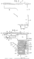
- a lower end portion of each bottom portion 41 and 42 rests upon a different lateral opposite end edge region of bottom shelf member 28 (see Figs. 2 and 4, for example).
- Bottom shelf member 28 on its underface is supported in desk 10 by a pair of upstanding flattened legs, or leg means, 29 each of which is in laterally spaced, parallel relationship to the other thereof, and each of which is laterally inset from its adjacent end of the bottom shelf member 28.
- Each of the side walls 12 and 13 is further provided with an integrally formed respective forward extension 36 and 37 along its upper edge region.
- Each such forward extension 36 and 37 supports along its respective top edge adjacent forward underface portions of top member 11.
- each such extension 36 and 37 provides an inside surface region for mounting a rail 34 by screws 31 or the like for an optional but preferred keyboard support platform 21.
- a transversely short keyboard holding or supporting platform 26 that is transversely and horizontally slidable from the closed position shown in Fig. 1 to a fully extended position whereat a keyboard which rests upon platform 26 is fully exposed and usable by a worker seated before front edge 23.
- Sliding capability is conveniently achieved by means of a pair of conventional rails 27 mounted one along each parallel lateral side of platform 26. The rails 27 engage the rails 34 to provide horizontal slidability for platform 26. While various structures for platform 26 can be employed, a presently preferred structure is shown and described in U.S. patent No. 5205631 filed October 10, 1991.
- each side wall 12 and 13 Between bottom adjacent portions of each side wall 12 and 13 extends a back brace 32. Adjacent to a mid-portion of back brace 32 in each of the sidewalls 12 and 13 a notched rectangularly configured cutout is provided. The cutout is adapted to accommodate, or house, an enclosed conventional cable channel (not shown).
- the cable channel housing can incorporate a base plate that is optionally mounted against the front face of back brace 32, and then a domed elongated cover structure can be associated with the base plate with the cover extending into the cutouts.
- Such a cable channel housing is useful in interconnecting together by appropriate wiring one or more desks 10 (and their respective monitor(s) and keyboard(s) (not shown) with a computer or central processing unit (CPU) (not shown)).
- each leg 29 is conveniently and preferably provided with a pair of transversely spaced adjustable screw-type levelers 33 which are conventionally threadably received into socket members (not shown) that are inset into the bottom edges of each leg 29.
- each leg 29 is conveniently secured to adjacent contacting bottom facial portions of the shelf member 28 by cross-head type screws or the like that extend through bottom shelf member 28 downwardly.
- the bottom edges of each side wall 12 and 13 that contact the bottom shelf member 28 are conveniently secured to the adjacent contacting upper facial portion of bottom shelf member 28 at each end of bottom shelf member 28 by cross-head type screws or the like that extend through shelf member upwardly.
- the back brace 32 is conveniently provided with a connector bolt 46 mounted so as to extend therefrom at respective locations approximately each of its four corners.
- the shank portion of each such bolt 46 is slidably received within a mating channel (not shown) formed in the back edge portions of each side wall 12 and 13.
- Conventional cam screws 47 associated with each such channel in the sidewalls 12 and 13 are then turned (by a screw driver) into engagement with respective bolts 46 to bring the back brace 32 into a desired tight engagement with the respective side panels 12 and 13.
- a plurality of projecting bolts or a combination of projecting bolts and studs 48 are inset into the upper horizontal edge portion of each side panel 12 and 13 at respective locations therealong which are aligned with mating channels provided along contacting surface portions of the underface of top member 11.
- top member 11 can have its top surface 11 leveled at an installation location by adjusting the levelers 33.
- the desk 10 can be secured by fastening means, such as screws, nut and bolt assemblies, or the like to an adjacent module panel (not drawn) or the like, such fastening means conveniently extending through holes 51 provided in back brace 32.
- fastening means such as screws, nut and bolt assemblies, or the like to an adjacent module panel (not drawn) or the like, such fastening means conveniently extending through holes 51 provided in back brace 32.
- the adjustable monitor support assembly that is associated with the desk structure 10 preferably has an open grill or mesh-like structure at least for its monitor supporting shelf surface so as to enhance heat dissipation from a monitor when in use.
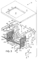
- an underdesk adjustable monitor support assembly 230 which is incorporated into the desk structure 10; this support assembly 230 is as shown and described in the above referenced European patent application number 91920142.6 (EP-A-0552295).
- the adjustable monitor support assembly 230 is conveniently and preferably comprised of formed heavy (i.e., relatively thick steel wire or the like) wire components that are interwelded together at locations of contact therebetween and then individual components are coated with an electrically insulating and mechanical shock (impact) absorbing material, such as is achieved by dipping into a conventional polyvinyl chloride plastisol coating composition and drying, or the like.
- an electrically insulating and mechanical shock (impact) absorbing material such as is achieved by dipping into a conventional polyvinyl chloride plastisol coating composition and drying, or the like.
- Such a coating layer is desirable for reasons of avoiding accidental physical impacts thereagainst with a monitor and/or avoiding accidental current flow through a component of a monitor support assembly, as those skilled in the art will appreciate.
- Assembly 230 incorporates a shelf member 231 having a flattened bottom support portion, or bottom member, or bottom support member, 232 and an integrally formed flattened back support portion, or back member, or back support member, 233 that upstands preferably perpendicularly and extends unitarily from a rear edge region, or rear edge, 234 of bottom member 232 (see Figures 2 and 4, for example).
- shelf member 231 incorporates a perimeter defining wire, or wire member, 236 which has a mid point located in the middle of the front edge 254 of bottom support member 232.
- wire 236 is bent at about 90 degrees relative to front edge 254 at each opposed end of front edge 254.
- opposed lateral side edges 237 and 238, respectively, of back member 233 the wire 236 is again bent in two places, each bend being at rear edge region 234 and being at about 90 degrees relative to each lateral side edge 255 and 256, respectively, and also perpendicular relative to front edge 254.
- each opposed lateral side edge 237 and 2308 the wire 236 is again bent, this time in two successive 90 degree turns, each such turn being in relatively closely spaced relationship to the other thereof, so as to produce a pair of short sections 240A and 240B therebetween which in effect together define the back upper end edge 240 of the back member 233.
- Such short sections 240A and 240B are preferably in spaced, parallel relationship to the front edge 254.
- Each such pair of successive 90 degree turns together with the sections 237A and 238A therebetween thus defines a generally U-shaped arrangement for wire 236 which provides strength for back member 233 and produces two lengths of the wire 236 that are in spaced, parallel, coplanar relationship to each other adjacent each lateral side edge 237 and 238, respectively.
- the wire 236 is once again bent at about a 90 degree angle at two locations, thereby to provide a pair of spaced, generally parallel lengths 257 and 258.
- These lengths 257 and 258 extend slightly out of parallel alignment (see Figure 4) with the respective portions of the wire 236 that define each of the lateral side edges 237 and 238, respectively, so that the wire 236 can undergo a final 90 degree turn to produce a pair of terminal wire sections 259 and 260 therein that are in an aligned, opposed, generally coaxial relationship with one another.
- Sections 259 and 260 each provide a supportive function, as hereinafter explained.
- Back member 233 is further provided with a pair of parallel, longitudinally (laterally relative to desk 10) extending, vertically (transversely relative to desk 10) spaced back member supporting wires, or wire members, 239 and also with a pair of parallel, and longitudinally (laterally relative to desk 10) extending, vertically (transversely relative to desk 10) spaced, shelf-supporting wires, or wire members, 241.
- One of the wires 241 which is adjacent the rear edge region 234 provides at lateral opposite ends, or end portions, of the shelf member 231a first pair of opposed shelf support means, or members, or shafts, 242A and 242B which extend laterally and longitudinally outwardly from the back member 233.
- the other one of the wires 241 which is spaced from the rear edge region 234, but which is preferably adjacent to a back edge 240 of back member 233, provides at the lateral opposite end portions of the shelf member 231 a second pair of opposed shelf support means, or members, or shafts, 243A and 243B which likewise extend laterally and longitudinally outwardly from the back member 233.
- bottom member 232 is provided with a plurality of spaced, parallel, transversely extending, bottom member supporting wires, or wire members, 244 which extend beyond the rear edge region 234, but which are bent upwards at rear edge region 234 at 90°. All wires 244 are welded to at least one of each of wires 241 and 239 at locations of contact therebetween, as well as to the wire 236 along front edge 254, thereby to provide a bottom support platform and to add to the rigidity desired for retaining the desired 90 degree angular relationship between back member 233 and bottom member 232.
- each of the wires 244 which contacts one of the terminal sections 259 and 260 is also welded thereto.
- shelf member 231 is itself supported and held along its opposite sides only by the respective opposed shelf support shafts 242 (paired) and 243 (paired).
- Support assembly 230 further incorporates a pair of generally rectangularly configured side supports 246A and 246B which are left and right mirror images of each other.
- Each side support 246A and 246B is oriented generally vertically and is disposed adjacent a different opposed lateral end edge, or lateral opposite end, of shelf member 231.
- each of the side supports 246A and 246B is preferably formed of heavy wire.
- each support 246A and 246B is defined along edge portions by a perimeter defining wire, or wire member, 247 which is folded (bent) inwardly to define a flange 252 in each side support 246A and 246B that extends outwardly relative to shelf member 231 along each transversely spaced front and rear edge of each side support 246 for structural support and rigidity purposes.
- each side support 246 has a slot 249 removed from the lower inside edge portion thereof for purposes of accommodating an enclosed cable channel housing (not shown) which, if used, runs lengthwise across the inside of back brace 32.
- a plurality of horizontally extending, vertically generally equally spaced load bearing members, or wires, or support wire members, 248 are provided for each side support 246.
- Wires 248 are each welded to respective associated wires 247 at each point of contact therebetween.
- the wires 248 thus provide a ladder-rung-like configuration which is utilized in mounting and positioning the shelf member 231 in the monitor support assembly 230 as shown and as described herein.
- each side support 246A and 246B that is, a top portion of wire 247
- U-clamps 262, C-configured brackets, or the like clamped by U-clamps 262, C-configured brackets, or the like, to a respective adjacent underside portion of desk top member 11 which is in adjacent relationship to the transparent member 19 that is inset into the top member 11 of the desk structure 10.
- the back edge wire portions of each side support 246 are similarly conveniently clamped against inside surface portions of back brace 32.
- One wire member 248A projects rearwardly and is bent downwardly at its terminus to define an "L" configuration which is convenient for use in clamp engagement.
- the bottom edge wire portions of each side support 246 rest against adjacent surface portions of shelf 28.
- the transverse width of the vertically extending body portion 41 and 42 of each side wall 12 and 13 is such that the vertically extending edge portion of the flange 252 of each side support 246A and 246B (as defined by perimeter wire 247) is in adjacent contacting relationship with a surface portion of each one respective associated body portion 41 and 42.
- each side support 246A and 246B is cooperatively associated with each of an adjacent side wall 12 and 13, and with adjacent portions of shelf member 28, back brace 32 and top member 11 in a fixed supportive and braced interrelationship.
- the monitor support assembly, or structure, 230 is provided with side supports which are effectively integrated into the desk structure 10.
- the shelf member 231 is vertically adjustably positionable and also adjustably tiltably positionable relative to the side supports 246.
- a monitor (not shown) is thus adjustably supportable and orientable by the shelf member 231. While the shelf member 231 can be joined to each of the side supports 246 by any convenient means, as those skilled in the art will readily appreciate; however, in the monitor support assembly 230, each of the support shafts 242 (paired) and 243 (paired) is adjustably positioned and held in a desired place relative to a side support 246 by adjustable supporting means comprising a locking block assembly 52, such as described in our aforereferenced European patent application number 91920142.6 (EP-A-0552295) which is fully incorporated hereinto by reference.
- the locking block assembly (52) comprises rung block means having a pair of generally vertically spaced, parallel, longitudinally open support grooves defined therein, each support groove extending through said rung block means and being slidably engagable with a different adjacent one of each of two of said load bearing members 248, and a longitudinally open shelf groove defined therein, said shelf groove extending perpendicularly relative to said support groove and terminating blindly in said rung block means, and including an overlying channel extending through said rung block means and intersecting one of said grooves; and locking block means having block means slidably extendable through said locking channel, and guidance means for limiting the sliding movement of said block means relative to said rung block means so that, when said locking block means is so engaged with said rung block means, said support grooves and said shelf groove are each closed and said locking block means is secured to wire means seated in
- the desk structure 10 has a transparent portion 19 in its flat top member 11 through which a monitor situated under such portion 19 can be viewed, for example, by a worker seated adjacent to the front edge of the top member 19.
- the desk structure 10 is also in cooperative association with the adjustable monitor support assembly 230 located under the top member 19.
- the monitor support assembly 230 has shelf member 231 adjustably supported at lateral opposite end portions thereof by respective ones of the pair of side supports 246A, 246B.
- Each side support 246A, 246B is cooperatively associated with the structural components 11, 12, 13, 28, 32 of the desk structure 10.
- the desk structure 10 is additionally provided with the keyboard-supporting platform 26 which is slidably horizontally movable from a storage position under the top member 11 to an extended position projecting outwardly from the front edge of the top member 11.
- the desk structure 10 is provided with mounting, or securing, means (not shown) for securing at least one component of the desk structure 10 to an adjacent structure, for example wall means such as a vertical modular wall panel or the like.
- the desk structure 10 is well adapted for use in a working area or office cubicle adjacent wall regions that are defined by modular wall panels or the like.
- the monitor support assembly 230 is adjustable.
- the desk structure 10 and the underdesk monitor support assembly 230 are cooperatively integrated with one another to provide a safe, effective, and efficient unitary combination.
- the desk structure 10 is relatively simple and reliable, and is easy to assemble from a kit or the like. Thereafter, the associated adjustable underdesk monitor support assembly 230 is easily and safely adjustable. If desired, the assembled desk structure 10 can be subsequently easily disassembled, relocated for use elsewhere, and reassembled.
- the desk structure 10 provides a maximal working area for a worker and is well suited for modular-type application and use environments.
Landscapes
- Tables And Desks Characterized By Structural Shape (AREA)
- Arrangement Of Elements, Cooling, Sealing, Or The Like Of Lighting Devices (AREA)
- Accommodation For Nursing Or Treatment Tables (AREA)
- Dry Shavers And Clippers (AREA)
- Devices For Indicating Variable Information By Combining Individual Elements (AREA)
- Casings For Electric Apparatus (AREA)
Claims (9)
- Schreibtisch (10), in Kombination umfassend(a) Bauelemente einschließlich:(1) einem oberen Element (11) mit einem transparenten Teil (19),(2) einem Paar von das obere Element (11) tragenden und dazwischen eine Knieöffnung definierenden Seitenwänden (12, 13), deren jede eine Unterkante und eine Hinterkante hat,(3) einem unteren Fachelement (28), das zwischen den Untersten der Seitenwände (12, 13) seitlich und nach hinten verläuft,(4) einer hinteren Verstrebung (32), die seitlich über die Hinterkanten der Seitenwände (12, 13) verläuft, und(5) Befestigungsmitteln (464, 47, 48, 49), die die besagten Bauelemente (11, 12, 13, 28, 32) aneinander befestigen,(b) eine unter dem oberen Element (11) befindliche Monitor-Traganordnung (230) mit(1) einem weiteren Fachelement (231) mit einem unteren Stützteil (232), einem hinteren Stützteil (233) und entgegengesetzten seitlichen Enden,(2) einem Paar von jeweils nahe einem der entgegengesetzten seitlichen Enden angeordneten Seitenstützen (246A, 246B),(3) Befestigungsmitteln, die die jeweilige Seitenstütze (246A, 246B) an den Bauelementen (11, 32) befestigen, und(4) einer verstellbaren Trageinrichtung (32), die die Seitenstützen (246A, 246B) mit den jeweils benachbarten entgegengesetzten seitlichen Enden des weiteren Fachelements (231) in Eingriff hält,(c) wobei die gegenseitige Beziehung zwischen den Bauelementen (11, 12, 13, 28, 32) und der Monitor-Traganordnung (230) zusätzlich so gestaltet ist, daß die Seitenstützen (246A, 246B) mit jeweils benachbarten Teilen einer der Seitenwände (12, 13) sowie mit dem oberen Element (11), dem unteren Fachelement (28) und der hinteren Verstrebung (32) in Berührung steht.
- Schreibtisch nach Anspruch 1, wobei das untere Fachelement (28) über ein Paar von in seitlichem Abstand angeordneten Beinanordnungen (29) in Abstand von einer Bodenfläche angehoben abstützbar ist.
- Schreibtisch nach Anspruch 1 oder 2 mit ferner Befestigungsmitteln zum Befestigen mindestens eines der Bauelemente an einer benachbarten Wandeinrichtung.
- Schreibtisch nach Anspruch 3, wobei die Befestigungsmittel geschraubt sind und zur Befestigung der hinteren Verstrebung (32) an der benachbarten Wandeinrichtung dienen, die ein Modulpaneel ist.
- Schreibtisch nach einem der vorhergehenden Ansprüche, wobei in der Monitor-Traganordnung (230) das weitere Fachelement (231) und die Seitenstützen (246A, 246B) jeweils aus Draht bestehen, und wobei(a) das hintere Stützteil (233) mit dem unteren Stützteil (232) einstückig ist und unter einem festen Winkel von deren Hinterkante aus verläuft, wobei das weitere Fachelement (231) ein erstes und ein zweites Paar von entgegengesetzten Fachabstützungen (242A, 242B, 243A, 243B) aufweist und die Abstützungen jedes Paares an jeweils einem der gegenüberliegenden seitlichen Enden seitlich herausragt,(b) wobei jedes der Paare von Seitenstützen (246A, 246B) mehrere in senkrechtem Abstand voneinander angeordnete Auflagerelemente (248) aufweist, und(c) wobei die verstellbare Stützeinrichtung (52) jede Abstützung des ersten und des zweiten Paares von entgegengesetzten Fachabstützungen (242A, 242B, 243A, 243B) jeweils einem der Lastauflagerelemente (248) zuordnet, so daß das weitere Fachelement (231) durch das Paar von Seitenstützen (246A, 246B) an einer geeigneten Stelle unter dem oberen Element (11) verstellbar abgestützt ist.
- Schreibtisch nach Anspruch 5, wobei das erste und das zweite Paar von entgegengesetzten Fachabstützungen (242A, 242B, 243A, 243B) in dem hinteren Stützteil (233) angeordnet ist.
- Schreibtisch nach einem der vorhergehenden Ansprüche, wobei ferner eine Tastatur-Tragplattform (26) vorhanden ist, die aus einer zurückgezogen Stellung unter und nahe dem oberen Element (11) in eine ausgefahrene Stellung nahe und vor einer vorderen Kante des oberen Elements (11) in horizontaler Richtung bewegbar ist und Schienenanordnungen (27) zur Gleitführung der horizontalen Bewegungen aufweist.
- Schreibtisch nach einem der vorhergehenden Ansprüche, wobei die verstellbare Stützeinrichtung (52) eine Verriegelungs-Blockanordnung aufweist.
- Schreibtisch nach Anspruch 8, wobei die Verriegelungs-Blockeinrichtung eine Sprossenblockierung aufweist, in der ein Paar von in generell senkrechtem Abstand angeordneten, parallelen, in Längsrichtung offenen Tragnuten, deren jede durch die Sprossenblockierung verläuft und mit dem jeweils benachbarten Lastauflagerelement (248) in Gleiteingriff steht, sowie eine in Längsrichtung offene Fachnut ausgebildet sind, die senkrecht zu der Tragnut verläuft und in der Sprossenblockierung blind endet, und wobei durch die Sprossenblockierung ein darüberliegender, eine der Nuten schneidender Kanal verläuft, und eine Verriegelungsblockierung mit einer durch den Blockeirkanal gleitend ausfahrbaren Blockiereinrichtung sowie einer Führung zur Begrenzung der Gleitbewegung der Blockiereinrichtung relativ zu der Sprossenblockierung, so daß dann, wenn die Verriegelungsblockierung auf diese Weise mit der Sprossenblockierung in Eingriff steht, die Tragnuten und die Fachnut jeweils geschlossen sind und die Verriegelungsblockierung an einer in den so geschlossenen Nuten sitzenden Drahteinrichtung befestigt ist.
Applications Claiming Priority (3)
| Application Number | Priority Date | Filing Date | Title |
|---|---|---|---|
| US07/778,333 US5294193A (en) | 1990-10-11 | 1991-10-17 | Modular desk with adjustable monitor support |
| US778333 | 1991-10-17 | ||
| PCT/US1992/008885 WO1993007779A1 (en) | 1991-10-17 | 1992-10-16 | Modular desk with adjustable monitor support |
Publications (3)
| Publication Number | Publication Date |
|---|---|
| EP0611283A1 EP0611283A1 (de) | 1994-08-24 |
| EP0611283A4 EP0611283A4 (de) | 1995-01-04 |
| EP0611283B1 true EP0611283B1 (de) | 1998-08-12 |
Family
ID=25112990
Family Applications (1)
| Application Number | Title | Priority Date | Filing Date |
|---|---|---|---|
| EP92922218A Expired - Lifetime EP0611283B1 (de) | 1991-10-17 | 1992-10-16 | Modularer schreibtisch mit regelbarer stützeinheit für monitore |
Country Status (8)
| Country | Link |
|---|---|
| US (1) | US5294193A (de) |
| EP (1) | EP0611283B1 (de) |
| JP (1) | JP3497506B2 (de) |
| AT (1) | ATE169466T1 (de) |
| AU (1) | AU660888B2 (de) |
| CA (1) | CA2121262C (de) |
| DE (1) | DE69226645T2 (de) |
| WO (1) | WO1993007779A1 (de) |
Families Citing this family (24)
| Publication number | Priority date | Publication date | Assignee | Title |
|---|---|---|---|---|
| US6431377B1 (en) | 1990-10-11 | 2002-08-13 | Nova Solutions, Inc. | Adjustable monitor support for flat monitors |
| GB9318700D0 (en) * | 1993-09-09 | 1993-10-27 | Jezewski Alec A | Desks and the like |
| FI1456U1 (fi) * | 1994-05-05 | 1994-08-11 | Jussi Korolainen | ADB-bord |
| DE4417873C1 (de) * | 1994-05-18 | 1995-07-13 | Laukamm Josten U | Schreibtisch |
| US5977434A (en) * | 1995-01-17 | 1999-11-02 | The Regents Of The University Of California | Procedures and materials for conferring disease resistance in plants |
| US5952485A (en) * | 1995-01-17 | 1999-09-14 | The Regents Of The University Of California | Procedures and materials for conferring disease resistance in plants |
| US5651594A (en) * | 1995-05-31 | 1997-07-29 | Nova Solutions, Inc. | Work station for use with flat monitors |
| US6092883A (en) * | 1995-05-31 | 2000-07-25 | Nova Solutions, Inc. | Work station for flat monitors |
| CH689293A5 (de) * | 1996-01-31 | 1999-02-15 | Scharer Soehne Ag | Möbel mit einer durchgehend ebenen Arbeitsfläche |
| US5699225A (en) * | 1996-08-02 | 1997-12-16 | Yavitz; Edward Q. | Combined work platform and personal computer system having a reflective display panel |
| US5791259A (en) * | 1997-04-04 | 1998-08-11 | B & W Corporation | Adjustable shelf support assembly computer work station |
| USD430570S (en) * | 1999-06-02 | 2000-09-05 | Khuay Hak Lee | CMS-CPU monitor support |
| US6419330B1 (en) * | 1999-06-07 | 2002-07-16 | Nova Solutions, Inc. | Enhanced access workstation |
| US6588548B1 (en) | 1999-11-23 | 2003-07-08 | Load King Manufacturing, Co. | Pharmacy workstation and method of operation |
| US20050145142A1 (en) | 2002-12-27 | 2005-07-07 | Jeffrey Korber | Method and apparatus for retrofitting a flat panel workstation system to existing desk tops and other like structures |
| US7047890B2 (en) * | 2002-12-27 | 2006-05-23 | Jeffrey Korber | Integrated flat panel workstation system |
| USD510821S1 (en) | 2004-01-30 | 2005-10-25 | Electronic Classroom Furniture Systems, Llc | Computer desk for a flip-up flat screen monitor |
| US7784412B2 (en) * | 2006-09-25 | 2010-08-31 | Korber Jeffrey H | Convertible computer display |
| US7757612B2 (en) * | 2006-09-25 | 2010-07-20 | Korber Jeffrey H | Convertible workstation |
| US20080315733A1 (en) * | 2007-06-22 | 2008-12-25 | Terry Bosch | Modular Monitor Support Apparatus |
| US20100283201A1 (en) * | 2009-05-06 | 2010-11-11 | Qua Erik N | Pinball table/dining table combination |
| US8749959B2 (en) * | 2009-09-29 | 2014-06-10 | Nati Brook Ventures, Llc | Modular technology furniture |
| USD743189S1 (en) | 2013-03-15 | 2015-11-17 | Herman Miller, Inc. | Workstation |
| CN109846211A (zh) * | 2019-01-31 | 2019-06-07 | 安徽力瀚科技有限公司 | 一种基于警务大数据中心服务装置及其操作方法 |
Family Cites Families (7)
| Publication number | Priority date | Publication date | Assignee | Title |
|---|---|---|---|---|
| BE764238A (fr) * | 1971-03-17 | 1971-09-13 | Lilly Industries Ltd | Derives de phenylalkylamine |
| CH560631A5 (de) * | 1974-06-24 | 1975-04-15 | Rottermann Robert | |
| US4590866A (en) * | 1984-02-16 | 1986-05-27 | Schairbaum Edward C | Work station with underdesk display |
| US5071204A (en) * | 1985-04-05 | 1991-12-10 | Engineered Data Products, Inc. | Desk-type computer work station |
| US4755009A (en) * | 1985-04-05 | 1988-07-05 | Engineered Data Products, Inc. | Work station apparatus for word processing equipment |
| US5125727A (en) * | 1990-10-11 | 1992-06-30 | Nova Office Furniture, Inc. | Adjustable monitor support assembly |
| US5087010A (en) * | 1990-10-26 | 1992-02-11 | Walters Gregory M | Speaker's prompting podium |
-
1991
- 1991-10-17 US US07/778,333 patent/US5294193A/en not_active Expired - Lifetime
-
1992
- 1992-10-16 EP EP92922218A patent/EP0611283B1/de not_active Expired - Lifetime
- 1992-10-16 WO PCT/US1992/008885 patent/WO1993007779A1/en not_active Ceased
- 1992-10-16 AT AT92922218T patent/ATE169466T1/de not_active IP Right Cessation
- 1992-10-16 CA CA002121262A patent/CA2121262C/en not_active Expired - Fee Related
- 1992-10-16 DE DE69226645T patent/DE69226645T2/de not_active Expired - Fee Related
- 1992-10-16 AU AU28757/92A patent/AU660888B2/en not_active Ceased
- 1992-10-16 JP JP50784693A patent/JP3497506B2/ja not_active Expired - Fee Related
Also Published As
| Publication number | Publication date |
|---|---|
| AU660888B2 (en) | 1995-07-06 |
| EP0611283A4 (de) | 1995-01-04 |
| EP0611283A1 (de) | 1994-08-24 |
| US5294193A (en) | 1994-03-15 |
| DE69226645D1 (de) | 1998-09-17 |
| CA2121262A1 (en) | 1993-04-29 |
| CA2121262C (en) | 1999-08-17 |
| ATE169466T1 (de) | 1998-08-15 |
| DE69226645T2 (de) | 1999-04-22 |
| JP3497506B2 (ja) | 2004-02-16 |
| AU2875792A (en) | 1993-05-21 |
| WO1993007779A1 (en) | 1993-04-29 |
| JPH07502664A (ja) | 1995-03-23 |
Similar Documents
| Publication | Publication Date | Title |
|---|---|---|
| AU660888B2 (en) | Modular desk with adjustable monitor support | |
| US5290099A (en) | Adjustable monitor support | |
| US5408939A (en) | Adjustable monitor support | |
| US5964164A (en) | Adjustable monitor support for flat monitors | |
| US5392934A (en) | Apparatus and method for adjustably supporting furnishings on a wall surface | |
| US5174532A (en) | Leg assembly | |
| CA2165707A1 (en) | System for setting up office and/or working environments | |
| US20040025754A1 (en) | Work station | |
| WO1992006616A1 (en) | Adjustable monitor support assembly | |
| HU222305B1 (hu) | Moduláris belső berendezési rendszer | |
| ES2033375T3 (es) | Puesto de trabajo para oficina. | |
| US6092774A (en) | Keyboard positioning system | |
| US3794281A (en) | Wall panel lateral support assembly and locking mechanism therefor | |
| US5312002A (en) | Utility tray | |
| JP4291031B2 (ja) | 連結デスク等における仕切パネルの取付構造 | |
| CN223081320U (zh) | 办公桌置物架 | |
| JPH09238755A (ja) | 机上用書棚装置 | |
| CN222264697U (zh) | 一种对座四人办公桌 | |
| JPH0722114Y2 (ja) | 棚装置 | |
| US4140064A (en) | Dual position table top support | |
| JPH0540750Y2 (de) | ||
| JP3033940U (ja) | 机 | |
| JPH0521Y2 (de) | ||
| JPH0636619Y2 (ja) | 電子機器載置台 | |
| JPS635066Y2 (de) |
Legal Events
| Date | Code | Title | Description |
|---|---|---|---|
| PUAI | Public reference made under article 153(3) epc to a published international application that has entered the european phase |
Free format text: ORIGINAL CODE: 0009012 |
|
| 17P | Request for examination filed |
Effective date: 19940513 |
|
| AK | Designated contracting states |
Kind code of ref document: A1 Designated state(s): AT BE CH DE DK ES FR GB GR IE IT LI NL SE |
|
| A4 | Supplementary search report drawn up and despatched |
Effective date: 19941118 |
|
| AK | Designated contracting states |
Kind code of ref document: A4 Designated state(s): AT BE CH DE DK ES FR GB GR IE IT LI NL SE |
|
| 17Q | First examination report despatched |
Effective date: 19960315 |
|
| GRAG | Despatch of communication of intention to grant |
Free format text: ORIGINAL CODE: EPIDOS AGRA |
|
| GRAG | Despatch of communication of intention to grant |
Free format text: ORIGINAL CODE: EPIDOS AGRA |
|
| GRAH | Despatch of communication of intention to grant a patent |
Free format text: ORIGINAL CODE: EPIDOS IGRA |
|
| GRAH | Despatch of communication of intention to grant a patent |
Free format text: ORIGINAL CODE: EPIDOS IGRA |
|
| GRAA | (expected) grant |
Free format text: ORIGINAL CODE: 0009210 |
|
| AK | Designated contracting states |
Kind code of ref document: B1 Designated state(s): AT BE CH DE DK ES FR GB GR IE IT LI NL SE |
|
| PG25 | Lapsed in a contracting state [announced via postgrant information from national office to epo] |
Ref country code: IT Free format text: LAPSE BECAUSE OF FAILURE TO SUBMIT A TRANSLATION OF THE DESCRIPTION OR TO PAY THE FEE WITHIN THE PRESCRIBED TIME-LIMIT;WARNING: LAPSES OF ITALIAN PATENTS WITH EFFECTIVE DATE BEFORE 2007 MAY HAVE OCCURRED AT ANY TIME BEFORE 2007. THE CORRECT EFFECTIVE DATE MAY BE DIFFERENT FROM THE ONE RECORDED. Effective date: 19980812 Ref country code: GR Free format text: LAPSE BECAUSE OF FAILURE TO SUBMIT A TRANSLATION OF THE DESCRIPTION OR TO PAY THE FEE WITHIN THE PRESCRIBED TIME-LIMIT Effective date: 19980812 Ref country code: ES Free format text: THE PATENT HAS BEEN ANNULLED BY A DECISION OF A NATIONAL AUTHORITY Effective date: 19980812 Ref country code: AT Free format text: LAPSE BECAUSE OF FAILURE TO SUBMIT A TRANSLATION OF THE DESCRIPTION OR TO PAY THE FEE WITHIN THE PRESCRIBED TIME-LIMIT Effective date: 19980812 |
|
| REF | Corresponds to: |
Ref document number: 169466 Country of ref document: AT Date of ref document: 19980815 Kind code of ref document: T |
|
| REG | Reference to a national code |
Ref country code: CH Ref legal event code: EP |
|
| REF | Corresponds to: |
Ref document number: 69226645 Country of ref document: DE Date of ref document: 19980917 |
|
| RAP2 | Party data changed (patent owner data changed or rights of a patent transferred) |
Owner name: NOVA SOLUTIONS, INC. |
|
| PG25 | Lapsed in a contracting state [announced via postgrant information from national office to epo] |
Ref country code: SE Free format text: LAPSE BECAUSE OF FAILURE TO SUBMIT A TRANSLATION OF THE DESCRIPTION OR TO PAY THE FEE WITHIN THE PRESCRIBED TIME-LIMIT Effective date: 19981112 Ref country code: DK Free format text: LAPSE BECAUSE OF FAILURE TO SUBMIT A TRANSLATION OF THE DESCRIPTION OR TO PAY THE FEE WITHIN THE PRESCRIBED TIME-LIMIT Effective date: 19981112 |
|
| REG | Reference to a national code |
Ref country code: IE Ref legal event code: FG4D |
|
| REG | Reference to a national code |
Ref country code: CH Ref legal event code: NV Representative=s name: KIRKER & CIE SA |
|
| NLT2 | Nl: modifications (of names), taken from the european patent patent bulletin |
Owner name: NOVA SOLUTIONS, INC. |
|
| ET | Fr: translation filed | ||
| PLBE | No opposition filed within time limit |
Free format text: ORIGINAL CODE: 0009261 |
|
| STAA | Information on the status of an ep patent application or granted ep patent |
Free format text: STATUS: NO OPPOSITION FILED WITHIN TIME LIMIT |
|
| 26N | No opposition filed | ||
| REG | Reference to a national code |
Ref country code: GB Ref legal event code: IF02 |
|
| PGFP | Annual fee paid to national office [announced via postgrant information from national office to epo] |
Ref country code: FR Payment date: 20021025 Year of fee payment: 11 |
|
| PGFP | Annual fee paid to national office [announced via postgrant information from national office to epo] |
Ref country code: NL Payment date: 20021031 Year of fee payment: 11 |
|
| PGFP | Annual fee paid to national office [announced via postgrant information from national office to epo] |
Ref country code: CH Payment date: 20021101 Year of fee payment: 11 |
|
| PGFP | Annual fee paid to national office [announced via postgrant information from national office to epo] |
Ref country code: BE Payment date: 20021219 Year of fee payment: 11 |
|
| PGFP | Annual fee paid to national office [announced via postgrant information from national office to epo] |
Ref country code: DE Payment date: 20031023 Year of fee payment: 12 |
|
| PG25 | Lapsed in a contracting state [announced via postgrant information from national office to epo] |
Ref country code: LI Free format text: LAPSE BECAUSE OF NON-PAYMENT OF DUE FEES Effective date: 20031031 Ref country code: CH Free format text: LAPSE BECAUSE OF NON-PAYMENT OF DUE FEES Effective date: 20031031 Ref country code: BE Free format text: LAPSE BECAUSE OF NON-PAYMENT OF DUE FEES Effective date: 20031031 |
|
| BERE | Be: lapsed |
Owner name: *NOVA SOLUTIONS INC. Effective date: 20031031 |
|
| PG25 | Lapsed in a contracting state [announced via postgrant information from national office to epo] |
Ref country code: NL Free format text: LAPSE BECAUSE OF NON-PAYMENT OF DUE FEES Effective date: 20040501 |
|
| REG | Reference to a national code |
Ref country code: CH Ref legal event code: PL |
|
| PG25 | Lapsed in a contracting state [announced via postgrant information from national office to epo] |
Ref country code: FR Free format text: LAPSE BECAUSE OF NON-PAYMENT OF DUE FEES Effective date: 20040630 |
|
| NLV4 | Nl: lapsed or anulled due to non-payment of the annual fee |
Effective date: 20040501 |
|
| REG | Reference to a national code |
Ref country code: FR Ref legal event code: ST |
|
| PGFP | Annual fee paid to national office [announced via postgrant information from national office to epo] |
Ref country code: IE Payment date: 20041013 Year of fee payment: 13 Ref country code: GB Payment date: 20041013 Year of fee payment: 13 |
|
| PG25 | Lapsed in a contracting state [announced via postgrant information from national office to epo] |
Ref country code: DE Free format text: LAPSE BECAUSE OF NON-PAYMENT OF DUE FEES Effective date: 20050503 |
|
| PG25 | Lapsed in a contracting state [announced via postgrant information from national office to epo] |
Ref country code: GB Free format text: LAPSE BECAUSE OF NON-PAYMENT OF DUE FEES Effective date: 20051016 |
|
| PG25 | Lapsed in a contracting state [announced via postgrant information from national office to epo] |
Ref country code: IE Free format text: LAPSE BECAUSE OF NON-PAYMENT OF DUE FEES Effective date: 20051017 |
|
| GBPC | Gb: european patent ceased through non-payment of renewal fee |
Effective date: 20051016 |
|
| REG | Reference to a national code |
Ref country code: IE Ref legal event code: MM4A |