EP0609543A1 - Verbesserung eines Skivorrichtung mit ein Ski ausgestattet mit solchen Vorrichtung - Google Patents
Verbesserung eines Skivorrichtung mit ein Ski ausgestattet mit solchen Vorrichtung Download PDFInfo
- Publication number
- EP0609543A1 EP0609543A1 EP93120492A EP93120492A EP0609543A1 EP 0609543 A1 EP0609543 A1 EP 0609543A1 EP 93120492 A EP93120492 A EP 93120492A EP 93120492 A EP93120492 A EP 93120492A EP 0609543 A1 EP0609543 A1 EP 0609543A1
- Authority
- EP
- European Patent Office
- Prior art keywords
- ski
- blade
- damping device
- damping
- flexion
- Prior art date
- Legal status (The legal status is an assumption and is not a legal conclusion. Google has not performed a legal analysis and makes no representation as to the accuracy of the status listed.)
- Granted
Links
Images


Classifications
-
- A—HUMAN NECESSITIES
- A63—SPORTS; GAMES; AMUSEMENTS
- A63C—SKATES; SKIS; ROLLER SKATES; DESIGN OR LAYOUT OF COURTS, RINKS OR THE LIKE
- A63C5/00—Skis or snowboards
- A63C5/06—Skis or snowboards with special devices thereon, e.g. steering devices
- A63C5/075—Vibration dampers
Definitions
- the present invention relates to a damping device for skiing, such as an alpine ski, a cross-country ski, a monoski or a snowboard. It relates more particularly to an improvement of this type of device, and also relates to a ski equipped with it.
- skis made thanks to a more or less flexible structure.
- the structure generally comprises peripheral protection elements, internal resistance elements to resist the flexural and torsional stresses, and a core. These elements are assembled by gluing or by injection, the assembly generally being carried out hot in a mold having the final shape of the ski, with a front part strongly raised in a tip, a rear part slightly raised in the heel, a central arched part. .
- the present invention seeks to remedy the various drawbacks mentioned above and proposes a particularly simple, effective and reliable solution to the problems of damping vibrations, by combining the advantages of dissipating vibrations locally by minimal deformations, and in a staggered manner. taking advantage of the much larger displacement.
- the device of the invention does not furthermore bring too much additional local stiffness to skiing.
- the damping device for damping the vibrations of a ski comprises a bending blade intended to be connected to the ski, and is characterized in that it comprises at least two damping means by which said blade is intended to be connected to the ski in a mobile manner, said damping means being connected by said flexion blade, so as to be spaced longitudinally by a certain distance.
- the bending blade is a blade, a profile or a metal rod, made of aluminum or steel, or made of composite material. It has a section between 5 and 300 mm2. Its length is between 100 and 1,200 millimeters. It should be noted that the blade is flexible in bending and does not generate static, additional bending stiffness (that is to say that the stiffness is negligible compared to the rest of the ski).
- At least one of the damping means is a flexible connection means constituted by an interface made of flexible material.
- the two damping means are flexible connection means constituted by a interface made of flexible material, and in particular a layer of viscoelastic material welded or glued to the bending blade.
- one of the damping means is of the dry friction type, while in a variant, it is of the viscous friction type.
- the invention also relates to a ski equipped with the damping device.
- Figures 1 to 3 show a first embodiment of the invention.
- Figure 1 is a side view, Figures 1a and 1b illustrating construction details.
- Figure 2 is a top view.
- Figure 3 is a side view of the ski in the bending position, Figures 3a and 3b illustrating operating details.
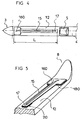
- Figures 4 and 5 show another embodiment, Figure 4 being a partial top view, while Figure 5 is a partial rear perspective view.
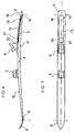
- Figures 6 and 7 show a variant of the invention, Figure 6 being a side view Figure 7 being a top view.
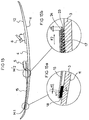
- Figures 8 to 10 illustrate an alternative embodiment, Figure 8 being a side view, Figure 9 being a top view, while Figure 10 is a sectional view along X-X.
- Figures 11 to 15 show another variant, Figure 11 being a side view, Figure 12 being a top view, Figures 13 and 14 being respectively sectional views along XIII-XIII and according to XIV-XIV.
- Figures 15, 15a and 15b illustrate the ski during bending.
- Figure 16 is a view similar to Figure 13 showing an alternative embodiment.
- Figures 17 to 20 show a variant, Figure 17 being a side view, while Figure 18 is a top view.
- Figures 19 and 20 being respectively sectional views along XIX-XIX and according
- Figure 21 is a side view according to a variant of the invention.
- Figure 22 is a sectional view of a detail according to a particular embodiment.
- Figures 23 and 24 are views respectively from above and along the axis (A, AO) of a surfboard equipped with the device according to the invention.
- the damping device (1) is intended to be connected to a ski bearing the general reference (2).
- Said ski being known per se, it will not be described in detail.
- it is constituted by an elongated beam (3) having its own distribution of thickness and width, therefore its own stiffness. It comprises a central part (4) also called a mounting area for the bindings (5, 6) intended to retain the boot on the ski, the front binding (5) being commonly called a stop, while the rear binding (6) is called usually heel.
- the front end (7) of the ski (2) is raised to form the tip (8), while the rear end (9) is also raised to form the heel (10) of the ski.
- the beam further comprises a lower sliding surface (11) and an upper surface (12). Note that the contact of the lower surface (11) with the snow takes place between the front contact point (13) and the rear contact point (14) corresponding to the places where said lower surface begins to rise.
- Said damping device bearing the general reference (1) consists of a flexion blade (15).
- the latter is for example constituted by an aluminum strip of thickness "e" between 1 and 5 millimeters, of width "l” between 10 and 60 millimeters and a length "L” between 100 and 1,200 millimeters.
- the flexion blade (15) is connected to the ski movably longitudinally by damping means, so as to be able to move in full and over its entire length relative to the ski.
- the first connection zone (16) of said flexion blade (15) is connected to the ski by first connection means (M1) while the second connection zone (17) of said blade (15) is connected to the ski by two second connecting means (M2).
- the second connection zone (17) is spaced longitudinally from the first connection zone (16) by an average distance (D), while the first (M1) and the second (M2) ) connecting means are also damping means.
- the damping device is, by way of example, placed at the front of the ski; thus, the bending blade (15) extends longitudinally over a length "L" between the front stop (5) and the front contact point (13).
- FIGS 1 to 3 illustrate a first embodiment according to which the two connecting means (M1, M2) are flexible.
- the front end constituting the first connection zone (16) of the flexion blade (15) is linked to the upper surface of the ski by a first damping means (M1) constituting the flexible connection means.
- M1 constituting the flexible connection means.
- an interface (18) produced by a layer of a flexible material of the elastic type and in particular of the viscoelastic type.
- This layer of thickness "e1" is bonded or welded on the one hand under the lower surface (19) of the blade, and on the other hand on the upper surface (12) of said ski (2).
- the first interface (18) is fixed under the blade (15) and on the upper surface (12) of the ski either by a thermosetting resin of the type polyester, vinyl ester or polyurethane epoxy, either by a thermoplastic film or any other means.
- the rear end constituting the second connection zone (17) of the flexion blade (15) is connected to the ski by a second damping means (M2) similar to the first means.
- M2 second damping means
- This layer of thickness "e2" is bonded or welded on the one hand under the lower surface (19) of the blade, and on the other hand on the upper surface (12) of said ski (2).
- the surface of the layer is between 200 and 6000 mm2.
- the shape of the layer can be rectangular, but can take any other form.
- the interface (20) is fixed under the blade (15) and on the upper surface of the ski, is carried out either by a thermosetting resin of the epoxy poylester, vinylester or polyurethane type, or by a thermoplastic film or any other means.
- Figures 1, 1a, 1b, 3, 3a and 3b illustrate schematically the operation of the damping.
- Figures 1, 1a and 1b show the ski in the rest state. In this rest situation, the point “a1" of the front end (16) of the blade corresponds to the point "b1" of the upper surface of the ski.
- the bending blade (15) moves longitudinally relative to the upper surface of the ski and it can be seen that the point “a1” has moved towards the forward, by a distance "d1" from the point "b1", while the point “a2” has moved backwards with respect to the corresponding point "b2", by a distance "d2".
- This displacement there is shearing of the layers of flexible material, and therefore damping.
- the choice of interface material and its dimensions determines the depreciation conditions.
- the two interfaces (18) and (20) could be strictly identical, but they can advantageously be different. They could for example have different dimensions and / or be made of a different material. Thus the thickness "e2" of the second interface (20) could be different, and for example greater than the thickness "e1" of the first interface (18), like this is illustrated in Figures 1 to 3. Likewise, the first interface (18) could be made of a harder material than the material of the second interface (20).
- the first interface (18) which is located in the zone where there is a maximum of energy of deformation by the third mode of bending and the first mode of torsion, must therefore dissipate these two types of vibration , and it can, for this purpose, be made of a viscoelastic material with a hardness of about 60 Shores A and have a thickness of about 0.5 millimeters.
- the second interface (20) which is located behind near the central zone (2) of the ski, must dissipate the first mode of flexion and it can be produced in a viscoelastic material with a hardness of less than 20 Shores A and have a thickness of 4 millimeters.
- the first interface (18) can be located in the area where there is maximum deformation energy by the second bending mode, and the second interface (20) which is located behind near the central zone (2) must dissipate the first bending mode.
- the flexion blade (15) constituting a connecting element between the two interfaces (18, 20), making it possible to obtain a relative displacement relative to the ski, greater from the rear end (17) thereof, as this is illustrated in FIGS. 3, 3a and 3b, where the displacement "d2" is greater than the displacement "d1".
- the bending blade can take any desired shape and in particular that which is illustrated by way of example, in FIGS. 4 and 5.
- the blade (15) is in the form of a profile having a central rib extending over a certain length of the blade, so as to avoid buckling of the blade.
- an enlarged zone (160) is linked to the surface of the ski by a front interface (180).
- the blade or profile can be produced by injection in charged plastic material.
- the modulus of the material as well as the section of the blade are chosen so as to obtain the desired stiffness in compression.
- the blade can be replaced by a simple cylindrical or rectangular rod of small section, so as not to exceed excessively high values of compression.
- damping device (1) can be placed on the ski, other than on the front, and in particular can be placed at the rear of the ski, as shown in FIGS. 6 and 7 where the elements similar to the previous embodiment, have the same references. Thus, all that has been described for the device placed at the front, illustrated in FIGS. 1 to 5, is valid for the device placed at the rear.
- the flexion blade could extend as far as the central zone (4) of the ski, as shown in FIGS. 8 to 10.
- the flexion blade (15) passes freely under the base plate (21) of the stop, the lower face of which comprises a hollow profile (22) whose dimensions are greater than the dimensions of said blade (15), to allow passage and free movement thereof.
- the two connecting and damping means are produced by a layer of viscoelastic material bonded to both the blade and the ski by bonding or welding, so that the damping is obtained by shearing the elastic layer, as we explained previously, but it could be otherwise. Indeed, one could imagine that only one of the damping means (M1 or M2) is produced by such a layer of glued flexible material serving as an interface, working in shear, while the other of the damping means (M2 or M1) is of the dry or viscous friction type.
- viscous friction should be understood to mean the friction that can be exerted during a relative displacement of the surface of the blade relative to the contact surface of a viscous fluid or of a viscoelastic material.
- Figures 11 to 16 illustrate a variant according to which the flexion blade (15) is connected to the ski at the front (16) by a damping means (M1) similar to those described above, while its rear end (17 ) is connected to the ski, movably longitudinally, by friction means (M'2) which consist of two layers (23, 24) of material with a high, dry coefficient of friction and a retaining and support stirrup (25).
- the material dry, high friction may be constituted for example by a layer of thermoplastic rubber or viscoelastic material.
- a first layer (23) of rubber is glued to the upper surface (12) of the ski, while a second layer (24) is glued under the central wall (26) of the retaining stirrup which has the shape ⁇ (omega) and which is fixed to the ski by screws (27).
- the rear end (17) of the bending blade can thus move along F1 and F2 between the first layer and the second layer of rubber.
- the stirrup maintains a pressure and clamps the blade between the two layers.
- the height (h) of the lower housing (28) of the stirrup is slightly less than the sum of the thicknesses of the blade and of the two layers when these are at rest, not pinched by the stirrup.
- Figures 15, 15a and 15b show the ski of Figures 11 to 14 during bending, illustrating the operation of the damping.
- the bending blade (15) moves longitudinally relative to the upper surface of the ski and it can be seen that the point “a1” has moved forward, by a distance “ d1 "with respect to the corresponding point" b1 ", while the rear end has moved rearward along F2, by a distance” d2 "and this movement has been slowed down by the friction layers (23, 24 ).
- the intensity or the clamping force of the bending blade between the two friction layers can be adjustable as a function of the damping which it is desired to obtain.
- Figure 16 is a view similar to Figure 13, showing an embodiment of the means for adjusting the clamping force, and therefore the intensity of friction.
- the stirrup (25) is not supported directly on the upper surface (12) of the ski, but supported on an elastic intermediate layer (29).
- the value of the tightening of the screws (27) defines the force of the tightening of the blade (15) between the two layers (23, 24) by varying the thickness (e4).
- Figures 17 to 20 illustrate a variant in which the flexion blade is connected to the ski at the front (16) by a damping means (M1) constituted by a flexible interface (18), as before, while the rear end (17) is connected to the ski movably longitudinally, by damping means (M2) of the viscous friction type which constitute a viscous mobile connection with the ski.
- the friction and absorption means (M "2) consist of a sheath or stirrup (30) fixed to the ski by screws (27) comprising a sliding housing for the bending blade, housing filled with 'a viscous material such as silicone-type grease, or a putty or the like.
- the sheath being constituted by a U-shaped stirrup, fixed to the ski and comprising an upper wall (31) and two lateral walls (32, 33).
- the sliding part of the bending blade (15) is in the sheath, completely surrounded by a layer of grease or putty forming a viscous film: an upper layer (34), a lower layer (35) and two lateral layers (36, 37) .
- the rear end (17) of the bending blade can thus move longitudinally inside the sleeve according to F1 and F2.
- the braking and therefore the damping are of course also carried out in the inverse relative displacements, that is to say according to F1, in the movements of return to the initial position and against the arrow.
- the viscous material can be of any type and for example have a viscosity at 40 degrees Celsius, between 20 and 1500 poises.
- the viscosity is around 400 poises.
- the material may be grease or a mineral or organic sealant.
- damping devices illustrated in FIGS. 11 to 20 could be arranged at the rear of the ski, as shown in FIGS. 6 and 7, in connection with the damping device in FIGS. 1 to 3.
- the damping means of the dry friction type (M'2) or of the viscous friction type (M "2) connect the rear end (17) of the blade (15), but it could be otherwise and it is in particular the front (16) of the flexion blade which could be connected to the ski by these means, while the rear end would be by the flexible damping means, that is to say those (18, 20) described and illustrated in Figures 1 to 3.
- FIG. 21 illustrates a particular mode where a third damping means (M3) is arranged between the modes (M1) and (M2), respectively at medium distance "D1" from (M1) and “D2” from (M2).
- the means (M3) can be of any type, as described above, that is to say of type with flexible interface, with dry or viscous friction.
- FIG. 22 illustrates the case of a device integrated into the structure of the ski.
- the ski is provided with a longitudinal internal housing (40) and allows the blade to move freely when the ski is stressed.
- the housing is covered with an internal reinforcing layer (41) and a protective and decorative top (42).
- Figures 23 and 24 illustrate the use of the device of the invention on a snowboard (43).
- AA ' axis which has a certain angle ( ⁇ ) with respect to the median longitudinal axis (BB') of the surf.
- BB' median longitudinal axis
- surfing is used asymmetrically; the surfer adopts a driving position which leads him to exert efforts towards the toes of the feet (in “front side") and in the direction of the heels (in “backside”) along an axis (CC ') corresponding substantially to the axis of symmetry of the fasteners (44, 45).
- the device may be advantageous to orient the device more or less by an angle ( ⁇ ) relative to the median longitudinal axis (BB ') of the surf. It goes without saying that the device could have another arrangement and in particular that illustrated in fine broken lines. According to this arrangement, the flexion blade (15 ′) is not in the axis (BB ′) of the snowboard (43) and extends substantially parallel to this axis.
Landscapes
- Vibration Prevention Devices (AREA)
- Fluid-Damping Devices (AREA)
- Vibration Dampers (AREA)
- Footwear And Its Accessory, Manufacturing Method And Apparatuses (AREA)
- Turbine Rotor Nozzle Sealing (AREA)
Applications Claiming Priority (2)
| Application Number | Priority Date | Filing Date | Title |
|---|---|---|---|
| FR9301427A FR2701215B1 (fr) | 1993-02-05 | 1993-02-05 | Perfectionnement pour dispositif d'amortissement pour ski et ski équipé d'un tel dispositif. |
| FR9301427 | 1993-02-05 |
Publications (2)
| Publication Number | Publication Date |
|---|---|
| EP0609543A1 true EP0609543A1 (de) | 1994-08-10 |
| EP0609543B1 EP0609543B1 (de) | 1998-05-13 |
Family
ID=9443881
Family Applications (1)
| Application Number | Title | Priority Date | Filing Date |
|---|---|---|---|
| EP93120492A Expired - Lifetime EP0609543B1 (de) | 1993-02-05 | 1993-12-18 | Ski mit einer Dämpfungsvorrichtung |
Country Status (6)
| Country | Link |
|---|---|
| US (1) | US5465994A (de) |
| EP (1) | EP0609543B1 (de) |
| JP (2) | JPH06238027A (de) |
| AT (1) | ATE165988T1 (de) |
| DE (1) | DE69318532T2 (de) |
| FR (1) | FR2701215B1 (de) |
Cited By (5)
| Publication number | Priority date | Publication date | Assignee | Title |
|---|---|---|---|---|
| EP0610272A1 (de) * | 1991-11-01 | 1994-08-17 | TINKLER, Michael, R. | Vorrichtung und verfahren zum dämpfen von ausschlägen und vibrationen von skiern |
| FR2725378A1 (fr) * | 1994-10-10 | 1996-04-12 | Salomon Sa | Ensemble pour ski comprenant un element de fixation associe a un dispositif d'amortissement |
| FR2729865A1 (fr) * | 1995-01-27 | 1996-08-02 | Salomon Sa | Paire de skis munis de dispositifs d'amortissement asymetriques de torsion |
| FR2748399A1 (fr) * | 1996-05-09 | 1997-11-14 | Rossignol Sa | Dispositif amortisseur de vibrations pour planche de glisse sur neige |
| FR2941627A1 (fr) * | 2009-01-30 | 2010-08-06 | Salomon Sas | Ski comportant un moyen d'amortissement des vibrations |
Families Citing this family (15)
| Publication number | Priority date | Publication date | Assignee | Title |
|---|---|---|---|---|
| FR2730390B1 (fr) * | 1995-02-10 | 1997-04-04 | Salomon Sa | Chaussure a flexibilite controlee |
| FR2737417B1 (fr) * | 1995-08-02 | 1997-08-29 | Rossignol Sa | Dispositif amortisseur de vibrations pour planche de glisse sur neige |
| US5820154A (en) * | 1997-04-29 | 1998-10-13 | Howe; John G. | Ski construction |
| FR2763862B1 (fr) | 1997-05-30 | 1999-08-27 | Salomon Sa | Dispositif interface entre une chaussure et un ski alpin |
| US6267402B1 (en) * | 1999-03-30 | 2001-07-31 | Nitinol Technologies, Inc. | Nitinol ski structures |
| AT412839B (de) * | 2000-06-02 | 2005-08-25 | Atomic Austria Gmbh | Gleitvorrichtung, insbesondere schi, snowboard oder dgl. |
| ITVE20030021A1 (it) * | 2003-06-10 | 2004-12-11 | Vittorio Quaggiotti | Sci da discesa. |
| US7607679B2 (en) * | 2004-11-23 | 2009-10-27 | Anton F. Wilson | Suspension system for a ski |
| WO2006088908A2 (en) * | 2005-02-16 | 2006-08-24 | Wilson Anton F | Snowboards |
| FR2895914B1 (fr) * | 2006-01-09 | 2008-07-04 | Skis Rossignol Sas Soc Par Act | Perfectionnement pour planche de glisse sur neige |
| FR2947182B1 (fr) * | 2009-06-26 | 2011-09-09 | Salomon Sas | Planche de glisse |
| DE102010047381A1 (de) * | 2010-10-05 | 2011-08-25 | Schnepf, Rolf, 76316 | Ski mit verstellbarer Vorspannung im Schaufelbereich |
| US9950242B2 (en) | 2015-06-19 | 2018-04-24 | Anton F. Wilson | Automatically adaptive ski |
| US10286288B1 (en) * | 2015-12-29 | 2019-05-14 | Alpine Radius Control Technologies, LLC | Torsional stabilizer for skis |
| WO2023035062A1 (en) * | 2021-09-08 | 2023-03-16 | Socpra Sciences Et Genie S.E.C. | A ski having a stabilizing section, a pair of skis and a stabilization device |
Citations (4)
| Publication number | Priority date | Publication date | Assignee | Title |
|---|---|---|---|---|
| DE3147140A1 (de) * | 1981-11-27 | 1983-06-01 | Fischer GmbH, 4910 Ried im Innkreis | Ski |
| EP0490044A1 (de) * | 1990-12-14 | 1992-06-17 | Salomon S.A. | Wintersportski bestehend aus einer Versteifung und einer Basis |
| EP0510308A1 (de) * | 1991-04-22 | 1992-10-28 | Salomon S.A. | Dämpfungsvorrichtung für Skier |
| EP0521272A1 (de) * | 1991-07-04 | 1993-01-07 | Salomon S.A. | Fortbildung für Dämppumpeinrichtung für Skis |
Family Cites Families (8)
| Publication number | Priority date | Publication date | Assignee | Title |
|---|---|---|---|---|
| US3260531A (en) * | 1964-01-31 | 1966-07-12 | Johan G F Heuvel | Terrain-conforming and torsionalresponsive skis |
| FR2503569A1 (fr) * | 1981-04-09 | 1982-10-15 | Rossignol Sa | Ski |
| AT383037B (de) * | 1984-05-18 | 1987-05-11 | Amf Sport Freizeitgeraete | Ski |
| FR2575393A1 (fr) * | 1984-12-27 | 1986-07-04 | Rossignol Sa | Ski de neige |
| FR2665081B1 (fr) * | 1990-07-30 | 1992-11-06 | Rossignol Sa | Surf de neige a caracteristiques asymetriques. |
| EP0490043B1 (de) * | 1990-12-14 | 1994-02-16 | Salomon S.A. | Ski mit laufflächenteil, ober Körper und Support für Bindungen |
| US5269555A (en) * | 1991-06-14 | 1993-12-14 | Ruffinengo Piero G | Modification of the flexibility of skis |
| US5284357A (en) * | 1991-11-01 | 1994-02-08 | Tinkler Michael R | Apparatus and method for damping deflections and vibrations in skis |
-
1993
- 1993-02-05 FR FR9301427A patent/FR2701215B1/fr not_active Expired - Fee Related
- 1993-12-18 DE DE69318532T patent/DE69318532T2/de not_active Expired - Fee Related
- 1993-12-18 EP EP93120492A patent/EP0609543B1/de not_active Expired - Lifetime
- 1993-12-18 AT AT93120492T patent/ATE165988T1/de active
-
1994
- 1994-02-02 JP JP6010744A patent/JPH06238027A/ja active Pending
- 1994-02-04 US US08/191,466 patent/US5465994A/en not_active Expired - Fee Related
-
1996
- 1996-10-29 JP JP1996010984U patent/JP3039526U/ja not_active Expired - Lifetime
Patent Citations (4)
| Publication number | Priority date | Publication date | Assignee | Title |
|---|---|---|---|---|
| DE3147140A1 (de) * | 1981-11-27 | 1983-06-01 | Fischer GmbH, 4910 Ried im Innkreis | Ski |
| EP0490044A1 (de) * | 1990-12-14 | 1992-06-17 | Salomon S.A. | Wintersportski bestehend aus einer Versteifung und einer Basis |
| EP0510308A1 (de) * | 1991-04-22 | 1992-10-28 | Salomon S.A. | Dämpfungsvorrichtung für Skier |
| EP0521272A1 (de) * | 1991-07-04 | 1993-01-07 | Salomon S.A. | Fortbildung für Dämppumpeinrichtung für Skis |
Cited By (6)
| Publication number | Priority date | Publication date | Assignee | Title |
|---|---|---|---|---|
| EP0610272A1 (de) * | 1991-11-01 | 1994-08-17 | TINKLER, Michael, R. | Vorrichtung und verfahren zum dämpfen von ausschlägen und vibrationen von skiern |
| EP0610272A4 (de) * | 1991-11-01 | 1995-04-19 | Michael R Tinkler | Vorrichtung und verfahren zum dämpfen von ausschlägen und vibrationen von skiern. |
| FR2725378A1 (fr) * | 1994-10-10 | 1996-04-12 | Salomon Sa | Ensemble pour ski comprenant un element de fixation associe a un dispositif d'amortissement |
| FR2729865A1 (fr) * | 1995-01-27 | 1996-08-02 | Salomon Sa | Paire de skis munis de dispositifs d'amortissement asymetriques de torsion |
| FR2748399A1 (fr) * | 1996-05-09 | 1997-11-14 | Rossignol Sa | Dispositif amortisseur de vibrations pour planche de glisse sur neige |
| FR2941627A1 (fr) * | 2009-01-30 | 2010-08-06 | Salomon Sas | Ski comportant un moyen d'amortissement des vibrations |
Also Published As
| Publication number | Publication date |
|---|---|
| DE69318532T2 (de) | 1998-11-12 |
| EP0609543B1 (de) | 1998-05-13 |
| DE69318532D1 (de) | 1998-06-18 |
| FR2701215B1 (fr) | 1995-04-14 |
| US5465994A (en) | 1995-11-14 |
| JP3039526U (ja) | 1997-07-22 |
| ATE165988T1 (de) | 1998-05-15 |
| FR2701215A1 (fr) | 1994-08-12 |
| JPH06238027A (ja) | 1994-08-30 |
Similar Documents
| Publication | Publication Date | Title |
|---|---|---|
| EP0609543A1 (de) | Verbesserung eines Skivorrichtung mit ein Ski ausgestattet mit solchen Vorrichtung | |
| EP0510308B1 (de) | Dämpfungsvorrichtung für Skier | |
| EP0521272B1 (de) | Fortbildung für Dämpfungseinrichtung für Skis | |
| EP0580935B1 (de) | Verbesserung an einer Amortisationseinrichtung für Skis | |
| EP0563569B1 (de) | Ski mit einer Lauffläche und einer zweiteiligen Versteifung, die an der Lauffläche angebracht ist | |
| EP0490043B1 (de) | Ski mit laufflächenteil, ober Körper und Support für Bindungen | |
| EP0490044A1 (de) | Wintersportski bestehend aus einer Versteifung und einer Basis | |
| EP0622096B1 (de) | Snowboard | |
| EP0813440B1 (de) | Vibrationsdämpfungseinrichtung für gleitbrett | |
| EP0498053A1 (de) | Ski für Wintersport mit Montagebühne für Skibindungen | |
| EP0682961A1 (de) | Abfahrtsski mit doppel wirkender Versteifungs- und/oder Dämpfungsvorrichtung | |
| EP1000641A1 (de) | Gleitgerät mit ein Bindungsträgerplatte an einem Ski | |
| EP0543744A1 (de) | Ski mit einem nicht-rechteckigen Durchschnitt | |
| EP2266672B1 (de) | Gleitbrett | |
| FR2719780A1 (fr) | Dispositif pour ski de fond et ski équipé d'un tel dispositif. | |
| EP0599041B1 (de) | Trägerplatte zwischen Ski und Bindung | |
| EP0738479A1 (de) | Schuh mit Vorlageeinstellung des Schaftes | |
| FR2675391A1 (fr) | Ski pour sport d'hiver comprenant un raidisseur et une embase. | |
| FR2670392A1 (fr) | Ski pour sport d'hiver constitue d'une embase et d'un raidisseur. | |
| FR2752743A1 (fr) | Planche de surf de neige munie d'un dispositif d'amortissement | |
| EP0692284A1 (de) | Skidämpfungsvorrichtung und mit einer solchen Vorrichtung ausgerüsteter Ski | |
| FR2760372A1 (fr) | Dispositif de raidissement pour planche de glisse | |
| FR2675390A1 (fr) | Ski pour sport d'hiver comprenant une embase, un raidisseur et un support pour fixations. | |
| FR2670393A1 (fr) | Ski pour sport d'hiver constitue d'une embase, d'un raidisseur, et d'un support pour fixations. | |
| EP0753330A1 (de) | Übungsmittel zum Erlernen des Skilanglaufs nach der Schlittschuhlaufschritttechnik |
Legal Events
| Date | Code | Title | Description |
|---|---|---|---|
| PUAI | Public reference made under article 153(3) epc to a published international application that has entered the european phase |
Free format text: ORIGINAL CODE: 0009012 |
|
| AK | Designated contracting states |
Kind code of ref document: A1 Designated state(s): AT CH DE IT LI |
|
| 17P | Request for examination filed |
Effective date: 19950110 |
|
| 17Q | First examination report despatched |
Effective date: 19950522 |
|
| GRAG | Despatch of communication of intention to grant |
Free format text: ORIGINAL CODE: EPIDOS AGRA |
|
| GRAG | Despatch of communication of intention to grant |
Free format text: ORIGINAL CODE: EPIDOS AGRA |
|
| GRAH | Despatch of communication of intention to grant a patent |
Free format text: ORIGINAL CODE: EPIDOS IGRA |
|
| GRAH | Despatch of communication of intention to grant a patent |
Free format text: ORIGINAL CODE: EPIDOS IGRA |
|
| GRAA | (expected) grant |
Free format text: ORIGINAL CODE: 0009210 |
|
| AK | Designated contracting states |
Kind code of ref document: B1 Designated state(s): AT CH DE IT LI |
|
| PG25 | Lapsed in a contracting state [announced via postgrant information from national office to epo] |
Ref country code: IT Free format text: LAPSE BECAUSE OF FAILURE TO SUBMIT A TRANSLATION OF THE DESCRIPTION OR TO PAY THE FEE WITHIN THE PRESCRIBED TIME-LIMIT;WARNING: LAPSES OF ITALIAN PATENTS WITH EFFECTIVE DATE BEFORE 2007 MAY HAVE OCCURRED AT ANY TIME BEFORE 2007. THE CORRECT EFFECTIVE DATE MAY BE DIFFERENT FROM THE ONE RECORDED. Effective date: 19980513 |
|
| REF | Corresponds to: |
Ref document number: 165988 Country of ref document: AT Date of ref document: 19980515 Kind code of ref document: T |
|
| REG | Reference to a national code |
Ref country code: CH Ref legal event code: EP |
|
| REF | Corresponds to: |
Ref document number: 69318532 Country of ref document: DE Date of ref document: 19980618 |
|
| PG25 | Lapsed in a contracting state [announced via postgrant information from national office to epo] |
Ref country code: LI Free format text: LAPSE BECAUSE OF NON-PAYMENT OF DUE FEES Effective date: 19981231 Ref country code: CH Free format text: LAPSE BECAUSE OF NON-PAYMENT OF DUE FEES Effective date: 19981231 |
|
| PLBE | No opposition filed within time limit |
Free format text: ORIGINAL CODE: 0009261 |
|
| STAA | Information on the status of an ep patent application or granted ep patent |
Free format text: STATUS: NO OPPOSITION FILED WITHIN TIME LIMIT |
|
| 26N | No opposition filed | ||
| REG | Reference to a national code |
Ref country code: CH Ref legal event code: PL |
|
| PG25 | Lapsed in a contracting state [announced via postgrant information from national office to epo] |
Ref country code: DE Free format text: LAPSE BECAUSE OF NON-PAYMENT OF DUE FEES Effective date: 19991001 |
|
| PGFP | Annual fee paid to national office [announced via postgrant information from national office to epo] |
Ref country code: AT Payment date: 20001207 Year of fee payment: 8 |
|
| PG25 | Lapsed in a contracting state [announced via postgrant information from national office to epo] |
Ref country code: AT Free format text: LAPSE BECAUSE OF NON-PAYMENT OF DUE FEES Effective date: 20011218 |