EP0607539B1 - Method and apparatus for making a graphic product - Google Patents
Method and apparatus for making a graphic product Download PDFInfo
- Publication number
- EP0607539B1 EP0607539B1 EP93119224A EP93119224A EP0607539B1 EP 0607539 B1 EP0607539 B1 EP 0607539B1 EP 93119224 A EP93119224 A EP 93119224A EP 93119224 A EP93119224 A EP 93119224A EP 0607539 B1 EP0607539 B1 EP 0607539B1
- Authority
- EP
- European Patent Office
- Prior art keywords
- sheet material
- peripheral edges
- printing
- machine readable
- printer
- Prior art date
- Legal status (The legal status is an assumption and is not a legal conclusion. Google has not performed a legal analysis and makes no representation as to the accuracy of the status listed.)
- Expired - Lifetime
Links
Images


Classifications
-
- B—PERFORMING OPERATIONS; TRANSPORTING
- B26—HAND CUTTING TOOLS; CUTTING; SEVERING
- B26D—CUTTING; DETAILS COMMON TO MACHINES FOR PERFORATING, PUNCHING, CUTTING-OUT, STAMPING-OUT OR SEVERING
- B26D7/00—Details of apparatus for cutting, cutting-out, stamping-out, punching, perforating, or severing by means other than cutting
- B26D7/27—Means for performing other operations combined with cutting
-
- B—PERFORMING OPERATIONS; TRANSPORTING
- B41—PRINTING; LINING MACHINES; TYPEWRITERS; STAMPS
- B41J—TYPEWRITERS; SELECTIVE PRINTING MECHANISMS, i.e. MECHANISMS PRINTING OTHERWISE THAN FROM A FORME; CORRECTION OF TYPOGRAPHICAL ERRORS
- B41J2/00—Typewriters or selective printing mechanisms characterised by the printing or marking process for which they are designed
- B41J2/315—Typewriters or selective printing mechanisms characterised by the printing or marking process for which they are designed characterised by selective application of heat to a heat sensitive printing or impression-transfer material
- B41J2/32—Typewriters or selective printing mechanisms characterised by the printing or marking process for which they are designed characterised by selective application of heat to a heat sensitive printing or impression-transfer material using thermal heads
-
- B—PERFORMING OPERATIONS; TRANSPORTING
- B26—HAND CUTTING TOOLS; CUTTING; SEVERING
- B26F—PERFORATING; PUNCHING; CUTTING-OUT; STAMPING-OUT; SEVERING BY MEANS OTHER THAN CUTTING
- B26F1/00—Perforating; Punching; Cutting-out; Stamping-out; Apparatus therefor
- B26F1/38—Cutting-out; Stamping-out
- B26F1/3806—Cutting-out; Stamping-out wherein relative movements of tool head and work during cutting have a component tangential to the work surface
-
- B—PERFORMING OPERATIONS; TRANSPORTING
- B41—PRINTING; LINING MACHINES; TYPEWRITERS; STAMPS
- B41J—TYPEWRITERS; SELECTIVE PRINTING MECHANISMS, i.e. MECHANISMS PRINTING OTHERWISE THAN FROM A FORME; CORRECTION OF TYPOGRAPHICAL ERRORS
- B41J11/00—Devices or arrangements of selective printing mechanisms, e.g. ink-jet printers or thermal printers, for supporting or handling copy material in sheet or web form
-
- B—PERFORMING OPERATIONS; TRANSPORTING
- B41—PRINTING; LINING MACHINES; TYPEWRITERS; STAMPS
- B41J—TYPEWRITERS; SELECTIVE PRINTING MECHANISMS, i.e. MECHANISMS PRINTING OTHERWISE THAN FROM A FORME; CORRECTION OF TYPOGRAPHICAL ERRORS
- B41J11/00—Devices or arrangements of selective printing mechanisms, e.g. ink-jet printers or thermal printers, for supporting or handling copy material in sheet or web form
- B41J11/26—Pin feeds
-
- B—PERFORMING OPERATIONS; TRANSPORTING
- B41—PRINTING; LINING MACHINES; TYPEWRITERS; STAMPS
- B41J—TYPEWRITERS; SELECTIVE PRINTING MECHANISMS, i.e. MECHANISMS PRINTING OTHERWISE THAN FROM A FORME; CORRECTION OF TYPOGRAPHICAL ERRORS
- B41J11/00—Devices or arrangements of selective printing mechanisms, e.g. ink-jet printers or thermal printers, for supporting or handling copy material in sheet or web form
- B41J11/26—Pin feeds
- B41J11/28—Pin wheels
-
- B—PERFORMING OPERATIONS; TRANSPORTING
- B41—PRINTING; LINING MACHINES; TYPEWRITERS; STAMPS
- B41J—TYPEWRITERS; SELECTIVE PRINTING MECHANISMS, i.e. MECHANISMS PRINTING OTHERWISE THAN FROM A FORME; CORRECTION OF TYPOGRAPHICAL ERRORS
- B41J11/00—Devices or arrangements of selective printing mechanisms, e.g. ink-jet printers or thermal printers, for supporting or handling copy material in sheet or web form
- B41J11/36—Blanking or long feeds; Feeding to a particular line, e.g. by rotation of platen or feed roller
- B41J11/42—Controlling printing material conveyance for accurate alignment of the printing material with the printhead; Print registering
-
- B—PERFORMING OPERATIONS; TRANSPORTING
- B41—PRINTING; LINING MACHINES; TYPEWRITERS; STAMPS
- B41J—TYPEWRITERS; SELECTIVE PRINTING MECHANISMS, i.e. MECHANISMS PRINTING OTHERWISE THAN FROM A FORME; CORRECTION OF TYPOGRAPHICAL ERRORS
- B41J11/00—Devices or arrangements of selective printing mechanisms, e.g. ink-jet printers or thermal printers, for supporting or handling copy material in sheet or web form
- B41J11/66—Applications of cutting devices
-
- B—PERFORMING OPERATIONS; TRANSPORTING
- B41—PRINTING; LINING MACHINES; TYPEWRITERS; STAMPS
- B41J—TYPEWRITERS; SELECTIVE PRINTING MECHANISMS, i.e. MECHANISMS PRINTING OTHERWISE THAN FROM A FORME; CORRECTION OF TYPOGRAPHICAL ERRORS
- B41J11/00—Devices or arrangements of selective printing mechanisms, e.g. ink-jet printers or thermal printers, for supporting or handling copy material in sheet or web form
- B41J11/66—Applications of cutting devices
- B41J11/663—Controlling cutting, cutting resulting in special shapes of the cutting line, e.g. controlling cutting positions, e.g. for cutting in the immediate vicinity of a printed image
-
- B—PERFORMING OPERATIONS; TRANSPORTING
- B41—PRINTING; LINING MACHINES; TYPEWRITERS; STAMPS
- B41J—TYPEWRITERS; SELECTIVE PRINTING MECHANISMS, i.e. MECHANISMS PRINTING OTHERWISE THAN FROM A FORME; CORRECTION OF TYPOGRAPHICAL ERRORS
- B41J11/00—Devices or arrangements of selective printing mechanisms, e.g. ink-jet printers or thermal printers, for supporting or handling copy material in sheet or web form
- B41J11/66—Applications of cutting devices
- B41J11/666—Cutting partly, e.g. cutting only the uppermost layer of a multiple-layer printing material
-
- B—PERFORMING OPERATIONS; TRANSPORTING
- B41—PRINTING; LINING MACHINES; TYPEWRITERS; STAMPS
- B41J—TYPEWRITERS; SELECTIVE PRINTING MECHANISMS, i.e. MECHANISMS PRINTING OTHERWISE THAN FROM A FORME; CORRECTION OF TYPOGRAPHICAL ERRORS
- B41J15/00—Devices or arrangements of selective printing mechanisms, e.g. ink-jet printers or thermal printers, specially adapted for supporting or handling copy material in continuous form, e.g. webs
- B41J15/04—Supporting, feeding, or guiding devices; Mountings for web rolls or spindles
- B41J15/06—Supporting, feeding, or guiding devices; Mountings for web rolls or spindles characterised by being applied to printers having stationary carriages
-
- B—PERFORMING OPERATIONS; TRANSPORTING
- B41—PRINTING; LINING MACHINES; TYPEWRITERS; STAMPS
- B41J—TYPEWRITERS; SELECTIVE PRINTING MECHANISMS, i.e. MECHANISMS PRINTING OTHERWISE THAN FROM A FORME; CORRECTION OF TYPOGRAPHICAL ERRORS
- B41J17/00—Mechanisms for manipulating page-width impression-transfer material, e.g. carbon paper
- B41J17/02—Feeding mechanisms
-
- B—PERFORMING OPERATIONS; TRANSPORTING
- B41—PRINTING; LINING MACHINES; TYPEWRITERS; STAMPS
- B41J—TYPEWRITERS; SELECTIVE PRINTING MECHANISMS, i.e. MECHANISMS PRINTING OTHERWISE THAN FROM A FORME; CORRECTION OF TYPOGRAPHICAL ERRORS
- B41J17/00—Mechanisms for manipulating page-width impression-transfer material, e.g. carbon paper
- B41J17/32—Detachable carriers or holders for impression-transfer material mechanism
-
- B—PERFORMING OPERATIONS; TRANSPORTING
- B41—PRINTING; LINING MACHINES; TYPEWRITERS; STAMPS
- B41J—TYPEWRITERS; SELECTIVE PRINTING MECHANISMS, i.e. MECHANISMS PRINTING OTHERWISE THAN FROM A FORME; CORRECTION OF TYPOGRAPHICAL ERRORS
- B41J17/00—Mechanisms for manipulating page-width impression-transfer material, e.g. carbon paper
- B41J17/36—Alarms, indicators, or feed-disabling devices responsible to material breakage or exhaustion
-
- B—PERFORMING OPERATIONS; TRANSPORTING
- B41—PRINTING; LINING MACHINES; TYPEWRITERS; STAMPS
- B41J—TYPEWRITERS; SELECTIVE PRINTING MECHANISMS, i.e. MECHANISMS PRINTING OTHERWISE THAN FROM A FORME; CORRECTION OF TYPOGRAPHICAL ERRORS
- B41J2/00—Typewriters or selective printing mechanisms characterised by the printing or marking process for which they are designed
- B41J2/315—Typewriters or selective printing mechanisms characterised by the printing or marking process for which they are designed characterised by selective application of heat to a heat sensitive printing or impression-transfer material
-
- B—PERFORMING OPERATIONS; TRANSPORTING
- B41—PRINTING; LINING MACHINES; TYPEWRITERS; STAMPS
- B41J—TYPEWRITERS; SELECTIVE PRINTING MECHANISMS, i.e. MECHANISMS PRINTING OTHERWISE THAN FROM A FORME; CORRECTION OF TYPOGRAPHICAL ERRORS
- B41J2/00—Typewriters or selective printing mechanisms characterised by the printing or marking process for which they are designed
- B41J2/315—Typewriters or selective printing mechanisms characterised by the printing or marking process for which they are designed characterised by selective application of heat to a heat sensitive printing or impression-transfer material
- B41J2/32—Typewriters or selective printing mechanisms characterised by the printing or marking process for which they are designed characterised by selective application of heat to a heat sensitive printing or impression-transfer material using thermal heads
- B41J2/325—Typewriters or selective printing mechanisms characterised by the printing or marking process for which they are designed characterised by selective application of heat to a heat sensitive printing or impression-transfer material using thermal heads by selective transfer of ink from ink carrier, e.g. from ink ribbon or sheet
-
- B—PERFORMING OPERATIONS; TRANSPORTING
- B41—PRINTING; LINING MACHINES; TYPEWRITERS; STAMPS
- B41J—TYPEWRITERS; SELECTIVE PRINTING MECHANISMS, i.e. MECHANISMS PRINTING OTHERWISE THAN FROM A FORME; CORRECTION OF TYPOGRAPHICAL ERRORS
- B41J25/00—Actions or mechanisms not otherwise provided for
- B41J25/304—Bodily-movable mechanisms for print heads or carriages movable towards or from paper surface
- B41J25/312—Bodily-movable mechanisms for print heads or carriages movable towards or from paper surface with print pressure adjustment mechanisms, e.g. pressure-on-the paper mechanisms
-
- B—PERFORMING OPERATIONS; TRANSPORTING
- B41—PRINTING; LINING MACHINES; TYPEWRITERS; STAMPS
- B41J—TYPEWRITERS; SELECTIVE PRINTING MECHANISMS, i.e. MECHANISMS PRINTING OTHERWISE THAN FROM A FORME; CORRECTION OF TYPOGRAPHICAL ERRORS
- B41J33/00—Apparatus or arrangements for feeding ink ribbons or like character-size impression-transfer material
- B41J33/14—Ribbon-feed devices or mechanisms
- B41J33/52—Braking devices therefor
Definitions
- the present invention relates to a method and apparatus for making a graphic product on sheet material. More particularly, the invention relates to the making of products with enhanced graphic features through a combination of printing and cutting operations, and the equipment and the processes utilized in making of the product.
- the equipment and processes have many uses such as making signs, graphic designs, characters and other products with graphic images, and may be used in the field of printing for the production of visual images from data bases.
- the apparatus utilizes a cutting tool that is guided in accordance with a predetermined program to cut alphanumeric characters and other graphic images from a sheet of vinyl material that is releasably secured by a pressure-sensitive adhesive to a carrier or liner.
- the apparatus is controlled by a microprocessor and includes a keyboard and fonts stored in a memory to prepare sign text. Once the text has been prepared, the apparatus cuts the alphanumeric characters or other graphic designs from the vinyl and the sign text or character is stripped away from the carrier as a whole and transferred to a sign board.
- US-A-4 815 869 is also related to the printing field, and discloses a method for printing multicolor images from computer stored information by means of a dot matrix printer.
- the problem to be solved by the invention is to coordinate the printing and cutting operations so that the above-mentioned requirement is fulfilled.
- the method and the apparatus ensure a precise correspondence between the printed material and the cut peripheral edges of the graphic image by controlling both the printing and the cutting operations by reference to features on the sheet material itself, those features being sprocket holes along the edges of the material or a positional reference track on the material.
- the apparatus which carries out the method, includes a first storage means that stores data defining the peripheral edges of a graphic image to be generated in the product.
- the data stored is machine readable data.
- a second storage means stores the data that defines the printed material in positional relationship within the peripheral edges of a graphic image in the product.
- the data defining the printed material is also stored as machine readable data.
- Printing means are connected with the second storage means and responds to the machine readable data to print printed material on the surface of a sheet material in positional relationship to the peripheral edges of the graphic image.
- cutting means connected with the first storage means responds to the stored data for cutting the sheet material along the peripheral edges of the graphic image. The cutting is controlled in accordance with the stored data whereby graphic images containing the printed material within the cut edges of the image are prepared from the sheet material.
- the printing means is a thermal printer having a printing head and a roller platen over which the sheet material is fed by drive means during the printing operation.
- the roller platen has a cylindrical support surface and supports the sheet material adjacent the printing head for movement relative to the head during the printing operation.
- the sheet material has a series of feed holes along the marginal edges
- the drive means has sets of sprockets that engage the holes at each marginal edge for positive feeding of the material over the platen.
- the set of sprockets may be movable relative to the roller platen in a plane that is tangential to the cylindrical support surface of the platen, and when the sprockets are arranged in a circular array, they move in a cylindrical plane that is tangent to the cylindrical support surface of the roller platen but larger in diameter to provide greater contact areas with the sheet material supported on the platen.
- signs, characters, designs and other graphic images can be produced with exact registration between the lines of cut and the printed image in multiple colors or halftones and with other printing features which significantly enhance the images.
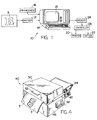
- Fig. 1 illustrates a microprocessor based system, generally designated 10, having apparatus for making signs, characters, designs and other graphic products with enhancements provided by the addition of color, halftones and other printed features.
- the letter "R" shown in Fig. 2 has printed halftone characteristics which imbue the letter with a three dimensional character.
- Such printed enhancements of the letter are quite distinctive and when such letters are cut along the peripheral edges C from a sheet material such as a vinyl sheet which can withstand weather, wear, abuse and other hazards rather well, a very attractive sign or other graphic product is generated.
- the letters "AR" shown in Fig. 3 can be prepared in two dimensional form on a single sheet of vinyl or other material with a three dimensional character by using different colors for the face of the letters and the shadow or third dimension.
- the system disclosed in Fig. 1 enables a graphic product to be created and produced with enhancements from a data base on which both the printed and cut features of the product are commonly based.
- the system 10 includes a digitizer 12 or other data input device which supplies a microprocessor based or other computer 14 with machine readable data defining at least the peripheral edges of the graphic product and possibly internal edges as well.
- the computer 14 displays the machine readable data defining the edges as an image on the screen 15.
- printed enhancements from the special enhancement programs in memory 16 printing designs are added within the edges of the displayed image with the aid of the computer as the operator or composer desires. All the edge and enhancement features are then referenced to one another in a common data base.
- the enhancement features may include special programs that allow halftone images such as the halftone features shown in Fig. 2 to be added within the peripheral edges of the pattern P.
- the memory 16 may include an entire font of halftone or otherwise enhanced characters including the edge data, in which case the data input to the computer 14 for the purposes of preparing a final product may be selected entirely from the memory.
- the digitizer may serve as the sole input device and may provide the critical data points defining the peripheral edges to be cut as well as the edges of the printing as in the enhanced letters "AR" shown in Fig. 3.
- Still other data sources may be utilized to supply the computer 14 with an infinite variety of graphic images with enhancements that can be produced by the system 10.
- the computer 14 From the data defining the enhanced graphic product, the computer 14 generates at least one printing program for operating a printer 20 that prepares one portion of the enhanced graphic product, and a cutting program that operates a cutter 22 and prepares the remaining portion of the product. Additional printing programs may also be generated, for example, to prepare additional printed material in different colors.
- Each program is stored in a memory 24, and when the product is to be produced, a controller 26 reads the programs and operates the printer 20 and cutter 22 respectively.
- the outline of the letters and the shadow of the third dimension are printed by the printer 20 on a sheet material, such as a vinyl secured by a pressure sensitive adhesive on a releasable backing material.
- a sheet material such as a vinyl secured by a pressure sensitive adhesive on a releasable backing material.
- SCOTCHCAL trademark of 3M Company.
- the printer prints the outline of the letters and third dimension in black or another color contrasting with the basic color or colors of the vinyl material.
- the printed sheet of vinyl on the releasable backing material is then mounted in the cutter 22 and the controller 26 cuts the vinyl only along the peripheral edges C of the image and any internal edges in accordance with the cutting program in the memory 24.
- the printing and cutting operations on the sheet of vinyl material are coordinated. After weeding to remove unwanted vinyl material within or around the image, the vinyl forming the enhanced graphic image is lifted from the underlying backing material and is attached to a sign board, window or other object.
- a unique printing apparatus for carrying out the printing operation is described in further detail below.
- a suitable cutting apparatus for carrying out the cutting operation on sheets of vinyl or other material is described in US-A-4 799 172.
- FIG. 4 One embodiment of a printer for accomplishing the printing operation disclosed in Fig. 1 is illustrated in Fig. 4.
- the printer 40 utilizes a set of sprockets to engage corresponding feed holes extending along each longitudinal edge of a strip S of the sheet material from which the graphic product is prepared, and correspondingly the cutter 22 has a set of sprockets to engage the same series of feed holes during the cutting operation.
- the feed holes become a proper reference for the image in both the printing and cutting operations.
- the printer can prepare a positional reference track T on the print-receiving surface of the sheet material to establish a known positional relationship between the printed image on the strip S and the strip itself.
- the cutting operation is then carried out by the cutter after the printing operation, and the cutter reads the positional reference track on the sheet material in order to coordinate the position of the material and the cutting tool with the printed material.
- the strip S is supplied in a roll which is supported on a platform 42 at the back side of the printer and is fed over a guide roller 44 before it enters the housing 46 of the printer. After the strip passes through the printer where the printing operation takes place, it is discharged freely at the front side of the machine or may be retrieved on a take-up reel if desired.
- the printer 40 is connected for controlling the printing operation to the controller 26 in Fig. 1, the printer includes a control panel 48 on the housing 46 to stop and start printing operations. Additionally the control panel 48 includes controls for slewing the strip S independently of the printing operation and other controls for operating the printer as will become more apparent hereafter.
- the upper portion of the printer 40 has a cover 50 with a handle 52 that can be opened and closed in order to expose the internal structure of the printer as shown more particularly in Figs. 5-10.
- the strip S passes over a roller platen 58 relative to a thermal print head 60 which is pressed downwardly onto the strip of material and generally establishes a linear zone of contact between the material and the platen.
- the strip of vinyl sheet material is 38 cm (15") wide and a hard rubber sleeve on the roller platen as well as the print head are approximately 30,5 cm (12") wide.
- a marginal edge portion of the strip overlaps the rubber sleeve 59 of the roller platen at each end as indicated in Fig. 8.
- a drive sprocket 62 having a set of sprocket pins engages a series of feed holes along the one marginal edge of the strip S, and a similar drive sprocket 64 having sprocket pins engages a series of feed holes along the opposite marginal edge of the strip.
- the drive sprockets 62,64 are fixedly mounted to a drive shaft 66.
- the drive shaft is rotatably mounted within the housing 46 of the printer and is driven from a step motor 70 by a series of drive gears 72,74, toothed drive pulleys 76,78 and a toothed drive belt 80.
- the roller platen 58 which is also rotatably mounted within the housing 46 is driven from the drive shaft 66 by means of drive pulleys 82,84 and an O-ring drive belt 86 at one end of the platen and drive pulleys 88,90 and an O-ring drive belt 92 at the opposite end of the platen.
- the gears, pulleys and toothed drive belt 80 ensure that the strip S of sheet material is precisely positioned on the roller platen and control the speed at which the strip S moves through the printer.
- the drive pulleys 82,84, 88,90 are selected to establish a peripheral speed of the roller platen 58 that is slightly higher than the peripheral speed of the drive sprocket 62 and 64 to augment the feeding of the strip S past the print head 60. Since the drive sprockets positively engage the strip and control the speed of the strip, the O-ring drive belts 86,92 must allow limited slip.
- a pair of curved, sheet metal plates 94,96 guide the strip S of sheet material circumaxially onto and off of the roller platen 58 and the cylindrical surfaces of the sprockets 62,64 in a U-shaped feed path.
- the cylindrical surfaces of the sprockets lie in a cylindrical plane which is much larger in diameter than the cylindrical, strip-engaging surface of the roller platen 58 and is tangential to the cylindrical surface.
- the cylindrical surface of the platen is formed by a hard rubber sleeve which improves the frictional engagement of the platen with the releasable backing material of the strip.
- novel printing and cutting apparatus may be carried out by a number of different printing and cutting machines.
- the use of the common sprocket drive means in the printer and cutter ensures coordination between the printed and cut subject matter; however, other indicia including a timing track printed on the strip of sheet material to be printed upon may also be used for the same coordination. While a separate printer and cutter have been disclosed, it is contemplated that a single machine having interchangeable heads or both printing and cutting heads might be used to carry out the two functions.
Landscapes
- Forests & Forestry (AREA)
- Engineering & Computer Science (AREA)
- Mechanical Engineering (AREA)
- Life Sciences & Earth Sciences (AREA)
- Handling Of Sheets (AREA)
- Electronic Switches (AREA)
- Common Mechanisms (AREA)
- Impression-Transfer Materials And Handling Thereof (AREA)
- Printers Characterized By Their Purpose (AREA)
- Dot-Matrix Printers And Others (AREA)
- Record Information Processing For Printing (AREA)
- Control Of Cutting Processes (AREA)
- Facsimiles In General (AREA)
- Delivering By Means Of Belts And Rollers (AREA)
- Accessory Devices And Overall Control Thereof (AREA)
Description
- The present invention relates to a method and apparatus for making a graphic product on sheet material. More particularly, the invention relates to the making of products with enhanced graphic features through a combination of printing and cutting operations, and the equipment and the processes utilized in making of the product. The equipment and processes have many uses such as making signs, graphic designs, characters and other products with graphic images, and may be used in the field of printing for the production of visual images from data bases.
- Within the signmaking field, the generation of graphic designs from a stored program is known from US-A-4 799 172. The apparatus utilizes a cutting tool that is guided in accordance with a predetermined program to cut alphanumeric characters and other graphic images from a sheet of vinyl material that is releasably secured by a pressure-sensitive adhesive to a carrier or liner. The apparatus is controlled by a microprocessor and includes a keyboard and fonts stored in a memory to prepare sign text. Once the text has been prepared, the apparatus cuts the alphanumeric characters or other graphic designs from the vinyl and the sign text or character is stripped away from the carrier as a whole and transferred to a sign board.
- US-A-4 815 869 is also related to the printing field, and discloses a method for printing multicolor images from computer stored information by means of a dot matrix printer.
- The demand for signs and other sheet material products with multicolored or enhanced graphic images is enormous. While multicolor printing is well known in the art and producing multicolored or enhanced signs by cutting graphic images in sheet material is also well known, a merger of these arts has not been previously employed to produce enhanced graphic images. Furthermore, the convenience, flexibility and speed of producing signs and other graphic images from computer data bases offers significant advantages and substantial opportunity for improvement.
- In the production of graphic products of the kind described above it is extremely important that the cutting and printing steps be precisely correlated with one another and the material so that registration between the lines of cut and the printed image is exact.
- The problem to be solved by the invention is to coordinate the printing and cutting operations so that the above-mentioned requirement is fulfilled.
- The invention solves this problem by the features of method claims 1 or 2 and apparatus claims 6 or 7.
- The method and the apparatus ensure a precise correspondence between the printed material and the cut peripheral edges of the graphic image by controlling both the printing and the cutting operations by reference to features on the sheet material itself, those features being sprocket holes along the edges of the material or a positional reference track on the material.
- The apparatus, which carries out the method, includes a first storage means that stores data defining the peripheral edges of a graphic image to be generated in the product. The data stored is machine readable data. A second storage means stores the data that defines the printed material in positional relationship within the peripheral edges of a graphic image in the product. The data defining the printed material is also stored as machine readable data.
- Printing means are connected with the second storage means and responds to the machine readable data to print printed material on the surface of a sheet material in positional relationship to the peripheral edges of the graphic image. Preferably thereafter, cutting means connected with the first storage means responds to the stored data for cutting the sheet material along the peripheral edges of the graphic image. The cutting is controlled in accordance with the stored data whereby graphic images containing the printed material within the cut edges of the image are prepared from the sheet material.
- In one embodiment of the invention, the printing means is a thermal printer having a printing head and a roller platen over which the sheet material is fed by drive means during the printing operation. The roller platen has a cylindrical support surface and supports the sheet material adjacent the printing head for movement relative to the head during the printing operation.
- Preferably the sheet material has a series of feed holes along the marginal edges, and the drive means has sets of sprockets that engage the holes at each marginal edge for positive feeding of the material over the platen. The set of sprockets may be movable relative to the roller platen in a plane that is tangential to the cylindrical support surface of the platen, and when the sprockets are arranged in a circular array, they move in a cylindrical plane that is tangent to the cylindrical support surface of the roller platen but larger in diameter to provide greater contact areas with the sheet material supported on the platen.
- As a result of the invention, signs, characters, designs and other graphic images can be produced with exact registration between the lines of cut and the printed image in multiple colors or halftones and with other printing features which significantly enhance the images.
- The invention will now be described with reference to the drawings in which
- Fig. 1 is a schematic diagram illustrating a system for printing and cutting signs and other graphic products in accordance with the present invention.
- Fig 2. is a three dimensional halftone image of the letter "R" that can be produced in accordance with the present invention.
- Fig. 3 is a three dimensional image of the letters "AR" that can be produced in accordance with the present invention.
- Fig. 4 shows one embodiment of a thermal printer that may be utilized in the present invention.
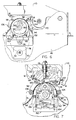
- Fig. 5 is a side elevation view of the thermal printer in Fig. 4 with portions broken away to show the internal structure.
- Fig. 6 is an enlarged fragmentary view of the printer as shown in Fig. 5 and shows the drive mechanism for moving a strip of sheet material relative to the print head.
- Fig. 7 is an enlarged fragmentary view of the printer similar to Fig. 6 and shows the print head, roller platen and sheet material detector.
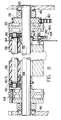
- Fig. 8 is a fragmentary front view showing the support structure and drive mechanism for the roller platen and drive sprockets.
- Fig. 1 illustrates a microprocessor based system, generally designated 10, having apparatus for making signs, characters, designs and other graphic products with enhancements provided by the addition of color, halftones and other printed features.
- For example, the letter "R" shown in Fig. 2 has printed halftone characteristics which imbue the letter with a three dimensional character. Such printed enhancements of the letter are quite distinctive and when such letters are cut along the peripheral edges C from a sheet material such as a vinyl sheet which can withstand weather, wear, abuse and other hazards rather well, a very attractive sign or other graphic product is generated.
- Similarly, the letters "AR" shown in Fig. 3 can be prepared in two dimensional form on a single sheet of vinyl or other material with a three dimensional character by using different colors for the face of the letters and the shadow or third dimension.
- The system disclosed in Fig. 1 enables a graphic product to be created and produced with enhancements from a data base on which both the printed and cut features of the product are commonly based. To produce a graphic product with enhancements, the system 10 includes a
digitizer 12 or other data input device which supplies a microprocessor based orother computer 14 with machine readable data defining at least the peripheral edges of the graphic product and possibly internal edges as well. Thecomputer 14 displays the machine readable data defining the edges as an image on thescreen 15. Then printed enhancements from the special enhancement programs inmemory 16 printing designs are added within the edges of the displayed image with the aid of the computer as the operator or composer desires. All the edge and enhancement features are then referenced to one another in a common data base. For example, the enhancement features may include special programs that allow halftone images such as the halftone features shown in Fig. 2 to be added within the peripheral edges of the pattern P. - Alternatively, the
memory 16 may include an entire font of halftone or otherwise enhanced characters including the edge data, in which case the data input to thecomputer 14 for the purposes of preparing a final product may be selected entirely from the memory. Still further, the digitizer may serve as the sole input device and may provide the critical data points defining the peripheral edges to be cut as well as the edges of the printing as in the enhanced letters "AR" shown in Fig. 3. Still other data sources may be utilized to supply thecomputer 14 with an infinite variety of graphic images with enhancements that can be produced by the system 10. - From the data defining the enhanced graphic product, the
computer 14 generates at least one printing program for operating aprinter 20 that prepares one portion of the enhanced graphic product, and a cutting program that operates acutter 22 and prepares the remaining portion of the product. Additional printing programs may also be generated, for example, to prepare additional printed material in different colors. Each program is stored in amemory 24, and when the product is to be produced, acontroller 26 reads the programs and operates theprinter 20 andcutter 22 respectively. - For example, to create the graphic image of the letters "AR" in Fig. 3, the outline of the letters and the shadow of the third dimension are printed by the
printer 20 on a sheet material, such as a vinyl secured by a pressure sensitive adhesive on a releasable backing material. One such vinyl is sold by the Assignee of this application under the trademark SCOTCHCAL of 3M Company. The printer prints the outline of the letters and third dimension in black or another color contrasting with the basic color or colors of the vinyl material. The printed sheet of vinyl on the releasable backing material is then mounted in thecutter 22 and thecontroller 26 cuts the vinyl only along the peripheral edges C of the image and any internal edges in accordance with the cutting program in thememory 24. - By utilizing a printing program and cutting program which have a common data base for defining both the peripheral edges to be cut as well as the printed material, the printing and cutting operations on the sheet of vinyl material are coordinated. After weeding to remove unwanted vinyl material within or around the image, the vinyl forming the enhanced graphic image is lifted from the underlying backing material and is attached to a sign board, window or other object.
- It is generally preferable, but not essential, to carry out the printing operation in the
printer 20 before the sheet material is cut by thecutter 22. With a separate printer and cutter it is also essential that the graphic image that is printed on the vinyl be registered in the cutter with the printing program origin and the cutting program origin coincident. In this manner the lines of cut and the printed portion of the image maintain the correspondence established by the common data base. This registration can be accomplished by printing an origin point on the vinyl along with the printed portion of the image and then optically aligning the origin point with a reference position for the material in thecutter 22. If the printing and cutting operations are carried out by a single machine or a machine having a common drive mechanism for positioning the vinyl relative to a printing head and a cutting head, then the origin point or other reference can be eliminated. - A unique printing apparatus for carrying out the printing operation is described in further detail below. A suitable cutting apparatus for carrying out the cutting operation on sheets of vinyl or other material is described in US-A-4 799 172.
- One embodiment of a printer for accomplishing the printing operation disclosed in Fig. 1 is illustrated in Fig. 4. The
printer 40 utilizes a set of sprockets to engage corresponding feed holes extending along each longitudinal edge of a strip S of the sheet material from which the graphic product is prepared, and correspondingly thecutter 22 has a set of sprockets to engage the same series of feed holes during the cutting operation. In this manner the registration of the cut edges of the graphic with the printed image is insured in the longitudinal direction. Since the graphic image is absolutely fixed both transversely and longitudinally on the strip S relative to the feed holes, the feed holes become a proper reference for the image in both the printing and cutting operations. - Alternatively, the printer can prepare a positional reference track T on the print-receiving surface of the sheet material to establish a known positional relationship between the printed image on the strip S and the strip itself. The cutting operation is then carried out by the cutter after the printing operation, and the cutter reads the positional reference track on the sheet material in order to coordinate the position of the material and the cutting tool with the printed material.
- As shown in Fig. 4 the strip S is supplied in a roll which is supported on a
platform 42 at the back side of the printer and is fed over aguide roller 44 before it enters thehousing 46 of the printer. After the strip passes through the printer where the printing operation takes place, it is discharged freely at the front side of the machine or may be retrieved on a take-up reel if desired. - Although the
printer 40 is connected for controlling the printing operation to thecontroller 26 in Fig. 1, the printer includes acontrol panel 48 on thehousing 46 to stop and start printing operations. Additionally thecontrol panel 48 includes controls for slewing the strip S independently of the printing operation and other controls for operating the printer as will become more apparent hereafter. - The upper portion of the
printer 40 has acover 50 with ahandle 52 that can be opened and closed in order to expose the internal structure of the printer as shown more particularly in Figs. 5-10. - Within the
printer 40, the strip S passes over aroller platen 58 relative to athermal print head 60 which is pressed downwardly onto the strip of material and generally establishes a linear zone of contact between the material and the platen. In one embodiment the strip of vinyl sheet material is 38 cm (15") wide and a hard rubber sleeve on the roller platen as well as the print head are approximately 30,5 cm (12") wide. Thus a marginal edge portion of the strip overlaps therubber sleeve 59 of the roller platen at each end as indicated in Fig. 8. Adrive sprocket 62, having a set of sprocket pins engages a series of feed holes along the one marginal edge of the strip S, and asimilar drive sprocket 64 having sprocket pins engages a series of feed holes along the opposite marginal edge of the strip. - As shown in Figs. 6 and 8, the
drive sprockets drive shaft 66. The drive shaft is rotatably mounted within thehousing 46 of the printer and is driven from astep motor 70 by a series of drive gears 72,74, toothed drive pulleys 76,78 and atoothed drive belt 80. In addition theroller platen 58 which is also rotatably mounted within thehousing 46 is driven from thedrive shaft 66 by means of drive pulleys 82,84 and an O-ring drive belt 86 at one end of the platen and drivepulleys ring drive belt 92 at the opposite end of the platen. The gears, pulleys andtoothed drive belt 80 ensure that the strip S of sheet material is precisely positioned on the roller platen and control the speed at which the strip S moves through the printer. The drive pulleys 82,84, 88,90 are selected to establish a peripheral speed of theroller platen 58 that is slightly higher than the peripheral speed of thedrive sprocket print head 60. Since the drive sprockets positively engage the strip and control the speed of the strip, the O-ring drive belts - As shown most clearly in Fig. 6 a pair of curved,
sheet metal plates roller platen 58 and the cylindrical surfaces of thesprockets roller platen 58 and is tangential to the cylindrical surface. Preferably the cylindrical surface of the platen is formed by a hard rubber sleeve which improves the frictional engagement of the platen with the releasable backing material of the strip. - It is clear that the novel printing and cutting apparatus may be carried out by a number of different printing and cutting machines. The use of the common sprocket drive means in the printer and cutter ensures coordination between the printed and cut subject matter; however, other indicia including a timing track printed on the strip of sheet material to be printed upon may also be used for the same coordination. While a separate printer and cutter have been disclosed, it is contemplated that a single machine having interchangeable heads or both printing and cutting heads might be used to carry out the two functions.
Claims (9)
- A method of making a graphic product from sheet material comprising: defining the peripheral edges (C) of a graphic image (P) in machine readable data, storing the machine readable data defining the peripheral edges (C) of the graphic image (P), cutting the sheet material (S) along the peripheral edges (C) of the graphic image (P) by means of a data-controlled cutter (22) controlled by the stored machine readable data defining the peripheral edges (C), characterized by defining printed material and its positional relationship within the peripheral edges (C) of the graphic image (P) in machine readable data, storing the machine readable data defining the printed material, and printing on an print-receiving surface of a sheet material (S) by means of a data-controlled printer (20, 40) controlled by the stored machine readable data defining the printed material to thereby place the printed material on the surface of the sheet material (S) in positional relationship to the peripheral edges (C) of the graphic image (P) whereby a graphic product containing printed material within the image is prepared from the sheet material (S), wherein the sheet material (S) is a strip of sheet material (S) having a series of feed holes extending along each longitudinal edge of the strip and the data controlled printer (20, 40) is a line printer placing print on the strip along a line extending transverse to the strip and the series of feed holes, and the steps of cutting and printing on the sheet material (S) include the step of engaging the strip of sheet material (S) and pulling the strip through the data controlled cutter (22) and printer (20, 40) by means of the series of feed holes along each edge to ensure a precise correspondence between the printed material and the cut, peripheral edges (C) of the graphic image (P).
- A method of making a graphic product from sheet material comprising: defining the peripheral edges (C) of a graphic image (P) in machine readable data, storing the machine readable data defining the peripheral edges (C) of the graphic image (P), cutting the sheet material (S) along the peripheral edges (C) of the graphic image (P) by means of a data-controlled cutter (22) controlled by the stored machine readable data defining the peripheral edges (C), characterized by defining printed material and its positional relationship within the peripheral edges (C) of the graphic image (P) in machine readable data, storing the machine readable data defining the printed material, and printing on an print-receiving surface of a sheet material (S) by means of a data-controlled printer (20, 40) controlled by the stored machine readable data defining the printed material to thereby place the printed material on the surface of the sheet material (S) in positional relationship to the peripheral edges (C) of the graphic image (P) whereby a graphic product containing printed material within the image is prepared from the sheet material (S), wherein the step of printing further includes printing a positional reference track (T) on the print-receiving surface of the sheet material (S) in addition to the printed material, the positional reference track and the printed material having a known positional relationship to each other, and the step of cutting is carried out after the step of printing the positional reference track (T) and includes reading the positional reference track (T) on the sheet material (S) to coordinate the position of the sheet material (S) and the data controlled cutter (22) with the printed material while cutting.
- A method of making a graphic product as defined in claim 1, characterized in that the step of printing on the surface of the sheet material (S) is accomplished before the step of cutting the sheet material (S).
- A method of making a graphic product from sheet material as defined in claim 1, 2 or 3, characterized in that the step of printing includes printing an origin for the graphic image (P) on the surface of the sheet material (S) in addition to the other printed material, and the step of cutting the sheet material (S) includes registering the printed origin with a corresponding origin for the step of cutting.
- A method of making a graphic product as defined in claim 1, 2, 3 or 4, characterized in that the step of printing includes printing some of the printed material on the sheet material (S) in one color, and printing more of the printed material in another color.
- An apparatus for making a graphic product from sheet material comprising: first storage means for storing data defining the peripheral edges (C) of a graphic image (P) as machine readable data, a cutter (22) connected with the first storage means (within 24) and responsive to the stored data for cutting the sheet material (S) along the peripheral edges (C) of the graphic image (P) characterized by second storage means (within 24) for storing data defining printed material and its positional relationship within the peripheral edges (C) of the graphic image (P) as machine readable data, and a printer (20, 40) connected with the second storage means (24) and responsive to the stored machine readable data for printing the printed material on a sheet material (S) in positional relationship to the peripheral edges (C) of the graphic image (P) whereby a graphic image (P) containing printed material within the peripheral edges (C) is prepared on the sheet material (S), said sheet material (S) having a series of feed holes extending along each longitudinal edge of the strip wherein the cutter (22) includes drive means having sets of sprocket pins which also engage the series of feed holes along each longitudinal edge of the strip (S) for feeding the strip through the cutter (22), and the printer (40) includes drive means (62, 64, 70) having sets of sprocket pins which engage the series of feed holes along each longitudinal edge of the strip (S) for feeding the strip through the printer, the printer being a line printer placing print on the strip along a line extending transverse to the series of feed holes along each edge of the strip.
- An apparatus for making a graphic product from sheet material comprising: first storage means for storing data defining the peripheral edges (C) of a graphic image (P) as machine readable data, a cutter (22) connected with the first storage means (within 24) and responsive to the stored data for cutting the sheet material (S) along the peripheral edges (C) of the graphic image (P) characterized by second storage means (within 24) for storing data defining printed material and its positional relationship within the peripheral edges (C) of the graphic image (P) as machine readable data, a printer (20, 40) connected with the second storage means (24) and responsive to the stored machine readable data for printing the printed material on a sheet material (S) in positional relationship to the peripheral edges (C) of the graphic image (P) whereby a graphic image (P) containing printed material within the peripheral edges (C) is prepared on the sheet material (S), and means for reading a positional reference track (T) having a known positional relationship on the print-receiving surface of the sheet material (S) with the other printed material to coordinate the position of the sheet material (S) and said cutter (22) with the printed material.
- An apparatus for making a graphic product as defined in claim 7, characterized in that the printer is a line printer (40).
- An apparatus for making a graphic product as defined in claim 6, 7 or 8, characterized in that the printer is a thermal printer (40).
Priority Applications (5)
| Application Number | Priority Date | Filing Date | Title |
|---|---|---|---|
| EP95105947A EP0672530B1 (en) | 1993-01-22 | 1993-11-29 | Printer with feed fault detector |
| EP95105937A EP0672529B1 (en) | 1993-01-22 | 1993-11-29 | Printer with sprocket and platen drive mechanism |
| EP95105948A EP0672532A1 (en) | 1993-01-22 | 1993-11-29 | Printer with coded replaceable web |
| EP95105949A EP0672534B1 (en) | 1993-01-22 | 1993-11-29 | Printer with pressure control |
| EP95105946A EP0672531A1 (en) | 1993-01-22 | 1993-11-29 | Replaceable cassette |
Applications Claiming Priority (2)
| Application Number | Priority Date | Filing Date | Title |
|---|---|---|---|
| US08/007,662 US5537135A (en) | 1993-01-22 | 1993-01-22 | Method and apparatus for making a graphic product |
| US7662 | 1993-01-22 |
Related Child Applications (4)
| Application Number | Title | Priority Date | Filing Date |
|---|---|---|---|
| EP95105937.7 Division-Into | 1995-04-20 | ||
| EP95105946.8 Division-Into | 1995-04-20 | ||
| EP95105948.4 Division-Into | 1995-04-20 | ||
| EP95105947.6 Division-Into | 1995-04-20 |
Publications (3)
| Publication Number | Publication Date |
|---|---|
| EP0607539A2 EP0607539A2 (en) | 1994-07-27 |
| EP0607539A3 EP0607539A3 (en) | 1994-10-12 |
| EP0607539B1 true EP0607539B1 (en) | 1997-05-02 |
Family
ID=21727461
Family Applications (6)
| Application Number | Title | Priority Date | Filing Date |
|---|---|---|---|
| EP95105937A Expired - Lifetime EP0672529B1 (en) | 1993-01-22 | 1993-11-29 | Printer with sprocket and platen drive mechanism |
| EP95105947A Expired - Lifetime EP0672530B1 (en) | 1993-01-22 | 1993-11-29 | Printer with feed fault detector |
| EP93119224A Expired - Lifetime EP0607539B1 (en) | 1993-01-22 | 1993-11-29 | Method and apparatus for making a graphic product |
| EP95105949A Expired - Lifetime EP0672534B1 (en) | 1993-01-22 | 1993-11-29 | Printer with pressure control |
| EP95105948A Withdrawn EP0672532A1 (en) | 1993-01-22 | 1993-11-29 | Printer with coded replaceable web |
| EP95105946A Withdrawn EP0672531A1 (en) | 1993-01-22 | 1993-11-29 | Replaceable cassette |
Family Applications Before (2)
| Application Number | Title | Priority Date | Filing Date |
|---|---|---|---|
| EP95105937A Expired - Lifetime EP0672529B1 (en) | 1993-01-22 | 1993-11-29 | Printer with sprocket and platen drive mechanism |
| EP95105947A Expired - Lifetime EP0672530B1 (en) | 1993-01-22 | 1993-11-29 | Printer with feed fault detector |
Family Applications After (3)
| Application Number | Title | Priority Date | Filing Date |
|---|---|---|---|
| EP95105949A Expired - Lifetime EP0672534B1 (en) | 1993-01-22 | 1993-11-29 | Printer with pressure control |
| EP95105948A Withdrawn EP0672532A1 (en) | 1993-01-22 | 1993-11-29 | Printer with coded replaceable web |
| EP95105946A Withdrawn EP0672531A1 (en) | 1993-01-22 | 1993-11-29 | Replaceable cassette |
Country Status (8)
| Country | Link |
|---|---|
| US (4) | US5537135A (en) |
| EP (6) | EP0672529B1 (en) |
| JP (1) | JP2905074B2 (en) |
| AU (5) | AU658082B2 (en) |
| CA (1) | CA2108516C (en) |
| DE (5) | DE69310765T2 (en) |
| ES (4) | ES2105805T3 (en) |
| SG (4) | SG60094A1 (en) |
Families Citing this family (101)
| Publication number | Priority date | Publication date | Assignee | Title |
|---|---|---|---|---|
| CA2107746A1 (en) * | 1992-10-06 | 1994-04-07 | Masahiko Nunokawa | Tape printing device and tape cartridge used therein |
| US6002416A (en) * | 1993-01-22 | 1999-12-14 | Gerber Scientific Products, Inc. | Method and apparatus for thermal transfer color printing |
| US5513919A (en) * | 1993-04-27 | 1996-05-07 | Gerber Scientific Products, Inc. | Method and apparatus for printing on sheet material |
| US5699166A (en) * | 1993-11-09 | 1997-12-16 | Seiko Epson Corporation | Copying machine for reproducing an image on a continuous web of labels |
| EP0704283A1 (en) * | 1994-09-13 | 1996-04-03 | Summagraphics N.V. | Method and device for cutting a pattern in a sheet material |
| US5986686A (en) * | 1995-05-12 | 1999-11-16 | Gerber Scientific Produccts, Inc. | Apparatus for making graphic products having a platen drive with encoded sprockets |
| US5769547A (en) * | 1995-08-18 | 1998-06-23 | Max Co., Ltd. | Thermal printer with pad for cleaning transfer sheet |
| US5841464A (en) * | 1995-10-25 | 1998-11-24 | Gerber Scientific Products, Inc. | Apparatus and method for making graphic products by laser thermal transfer |
| US5808654A (en) * | 1995-11-15 | 1998-09-15 | Gerber Scientific Products, Inc. | Apparatus for printing graphic images on sheet material having an ink web cassette with constant web tension |
| EP0774728B1 (en) * | 1995-11-20 | 2003-02-12 | Seiko Epson Corporation | Magnetic ink character detection apparatus and method |
| US5724084A (en) | 1995-12-05 | 1998-03-03 | Gerber Scientific Products, Inc. | Apparatus for making graphic products having a calibrated print head, and method of calibrating same |
| US5798783A (en) * | 1996-04-30 | 1998-08-25 | Eastman Kodak Company | Thermal printer with sensor for leading edge of receiver sheet |
| US5810494A (en) * | 1996-09-06 | 1998-09-22 | Gerber Systems Corporation | Apparatus for working on sheets of sheet material and sheet material for use therewith |
| US5846005A (en) * | 1996-09-09 | 1998-12-08 | Primera Technology, Inc. | Label printer with cutter attachment |
| US5765481A (en) * | 1997-03-11 | 1998-06-16 | Gerber Scientific Products, Inc. | Apparatus and method for working on a length of web material |
| US5868507A (en) * | 1997-04-09 | 1999-02-09 | Gerber Scientific Products, Inc. | Plotter having sprockets for driving sheets relative to a tool carriage and a fixed sheet support extending between the sprockets |
| CA2243722A1 (en) * | 1997-07-25 | 1999-01-25 | Asahi Kogaku Kogyo Kabushiki Kaisha | Image-forming system |
| AU733858B2 (en) | 1997-10-01 | 2001-05-31 | Boston Scientific Limited | Pelvic floor reconstruction |
| JP3589441B2 (en) * | 1997-10-06 | 2004-11-17 | 株式会社ミマキエンジニアリング | Cutting plotter and sealing material cutting method using the plotter |
| US5835118A (en) * | 1997-10-09 | 1998-11-10 | Eastman Kodak Company | Dye cartridge system and method adapted to tension a dye ribbon associated therewith |
| FR2769541B1 (en) * | 1997-10-15 | 1999-12-03 | Enduction Et De Flockage Soc D | METHOD FOR PRINTING MULTI-COLORED PATTERNS ON A HIGH-FREQUENCY WELDABLE OR WELDABLE FLOCKE FILM, FILM OBTAINED BY THIS PROCESS, METHOD FOR APPLYING THIS FILM ON A MEDIUM TO BE DECORATED AND DECORATED MEDIUM OBTAINED BY THIS PROCESS |
| US6482285B2 (en) * | 1998-01-20 | 2002-11-19 | Stahls' Inc. | Method of creating a transfer |
| US6106645A (en) * | 1998-01-21 | 2000-08-22 | Gerber Scientific Products, Inc. | Method and apparatus for manufacturing a graphic product |
| US6173211B1 (en) | 1998-04-15 | 2001-01-09 | Gerber Technology, Inc. | Apparatus and method for fabric printing of nested |
| US6205088B1 (en) | 1998-05-14 | 2001-03-20 | Gerber Scientific Products, Inc. | Thermal graphic pen and method of use |
| US5964541A (en) * | 1998-07-28 | 1999-10-12 | Ncr Corporation | Thermal printer apparatus |
| US6099178A (en) * | 1998-08-12 | 2000-08-08 | Eastman Kodak Company | Printer with media supply spool adapted to sense type of media, and method of assembling same |
| CA2277194A1 (en) * | 1998-08-12 | 2000-02-12 | Robert W. Spurr | A printer media supply spool adapted to allow the printer to sense type of media, and method of assembling same |
| CA2246965C (en) | 1998-09-15 | 2001-08-28 | Leung Tom | Self-aligning, minimal self-torque golf clubs |
| EP1013455B1 (en) | 1998-12-22 | 2006-02-15 | Eastman Kodak Company | A printer with donor and receiver media supply trays each adapted to allow a printer to sense type of media therein, and method of assembling the printer and trays |
| US6644544B1 (en) | 1999-06-16 | 2003-11-11 | Eastman Kodak Company | Imaging apparatus capable of forming an image consistent with type of imaging consumable loaded therein and method of assembling the apparatus |
| US6266075B1 (en) * | 1999-07-08 | 2001-07-24 | Brady Worldwide, Inc. | Printer with memory device for storing platen pressures |
| US6363239B1 (en) | 1999-08-11 | 2002-03-26 | Eastman Kodak Company | Print having attached audio data storage and method of providing same |
| US6772661B1 (en) | 1999-10-04 | 2004-08-10 | Mikkelsen Graphic Engineering | Method and apparatus for precision cutting and the like of graphics areas from sheets |
| US6785739B1 (en) | 2000-02-23 | 2004-08-31 | Eastman Kodak Company | Data storage and retrieval playback apparatus for a still image receiver |
| ATE229886T1 (en) * | 2000-03-02 | 2003-01-15 | Gerber Scient Products Inc | METHOD AND DEVICE FOR PRODUCING A GRAPHIC PRODUCT |
| US20030127008A1 (en) * | 2000-05-23 | 2003-07-10 | Stephane Smith | Method of generating a graphic image on fabric and a graphic product generated |
| US6506324B1 (en) | 2000-03-27 | 2003-01-14 | Gerber Scientific Products, Inc. | Method for embossing a sheet-type work material |
| US6689035B1 (en) | 2000-04-11 | 2004-02-10 | Gerber Scientific Products, Inc. | Method and apparatus for designing and creating a package |
| US6401616B1 (en) * | 2000-05-08 | 2002-06-11 | Gerber Scientific Products, Inc. | Method and material for making a coating blanket for use in printing presses |
| US6527356B1 (en) | 2000-06-02 | 2003-03-04 | Eastman Kodak Company | Printer capable of forming an image on a receiver substrate according to type of receiver substrate and a method of assembling the printer |
| USD458295S1 (en) | 2000-07-27 | 2002-06-04 | Iimak | Printer cassette |
| USD453179S1 (en) | 2000-07-27 | 2002-01-29 | Iimak | Printer cassette |
| US6797103B2 (en) | 2001-03-12 | 2004-09-28 | Mikkelsen Graphic Engineering Inc. | Automatic waste-area removal method and apparatus |
| JP2002301690A (en) | 2001-03-30 | 2002-10-15 | Max Co Ltd | Cutting machine |
| US6619167B2 (en) | 2001-04-05 | 2003-09-16 | Steen Mikkelsen | Method and apparatus for precision cutting of graphics areas from sheets |
| US6672187B2 (en) | 2001-04-05 | 2004-01-06 | Mikkelsen Graphic Engineering, Inc. | Method and apparatus for rapid precision cutting of graphics areas from sheets |
| CA2360971A1 (en) * | 2001-04-23 | 2002-10-23 | Zih Corporation | Ribbon drive and tensioning system for a print and apply engine or a printer |
| US7164490B2 (en) * | 2001-06-15 | 2007-01-16 | Eastman Kodak Company | Custom cut image products |
| US6632036B2 (en) * | 2001-08-23 | 2003-10-14 | Hewlett-Packard Development Company, L.P. | System and method for image formation through lamination |
| JP3712059B2 (en) * | 2001-11-05 | 2005-11-02 | シチズン時計株式会社 | Thermal transfer printer |
| US20030168148A1 (en) * | 2002-01-30 | 2003-09-11 | Gerber Scientific Products, Inc. | Apparatus and method for printing and cutting customized wall decorations |
| JP2005516803A (en) * | 2002-02-08 | 2005-06-09 | ガーバー サイエンティフィック プロダクツ インコーポレイテッド | Image forming method and image forming apparatus |
| US7325916B2 (en) * | 2002-02-08 | 2008-02-05 | Gerber Scientific International, Inc. | Method and apparatus for making signs |
| JP3665035B2 (en) * | 2002-04-04 | 2005-06-29 | ニスカ株式会社 | Printing apparatus and printing method |
| US20030228829A1 (en) * | 2002-06-07 | 2003-12-11 | Falk Ned R. | Splash Hoop |
| US7233498B2 (en) | 2002-09-27 | 2007-06-19 | Eastman Kodak Company | Medium having data storage and communication capabilities and method for forming same |
| JP3658392B2 (en) * | 2002-12-27 | 2005-06-08 | キヤノン電子株式会社 | Signal output device and sheet material processing apparatus provided with signal output device |
| US20040188012A1 (en) * | 2003-03-31 | 2004-09-30 | Westberg Aaron R | Custom gauge panel and system and method for manufacture thereof |
| KR101309950B1 (en) * | 2003-04-01 | 2013-09-17 | 어댑트시스, 엘티디. | Plastic embossed carrier tape apparatus and process |
| US20040216628A1 (en) * | 2003-04-30 | 2004-11-04 | Michael Nordlund | Dual-speed drive mechanism |
| CA2526123C (en) * | 2003-07-15 | 2009-09-15 | Mimaki Engineering Co., Ltd. | Register mark reader for cutting plotter and register mark reading method |
| GB2405832B (en) * | 2003-09-12 | 2007-04-11 | Ultra Electronics Ltd | Printer |
| US7109986B2 (en) | 2003-11-19 | 2006-09-19 | Eastman Kodak Company | Illumination apparatus |
| US7145464B2 (en) * | 2003-11-19 | 2006-12-05 | Eastman Kodak Company | Data collection device |
| US7009494B2 (en) | 2003-11-21 | 2006-03-07 | Eastman Kodak Company | Media holder having communication capabilities |
| KR100716011B1 (en) | 2003-12-02 | 2007-05-08 | 닛산 지도우샤 가부시키가이샤 | Manufacture of fuel cell |
| JP2005212078A (en) * | 2004-02-02 | 2005-08-11 | Graphtec Corp | Cut data making method of cutting plotter |
| JP4672265B2 (en) * | 2004-02-02 | 2011-04-20 | グラフテック株式会社 | Cutting plotter |
| US8156852B2 (en) * | 2004-01-22 | 2012-04-17 | Graphtec Kabushiki Kaisha | Cutting plotter, cutting plotter driving control device, cut target medium supporting sheet, cut target medium, cutting pen, method of manufacturing paper product, and method of generating cut data |
| GB2413451B (en) * | 2004-04-23 | 2006-04-26 | Myfotowall Ltd | Wallpaper printing system |
| US7140283B2 (en) * | 2004-05-05 | 2006-11-28 | Mikkelsen Graphic Engineering | Automated method and apparatus for vision registration of graphics areas operating from the unprinted side |
| US8035482B2 (en) * | 2004-09-07 | 2011-10-11 | Eastman Kodak Company | System for updating a content bearing medium |
| GB2418131A (en) * | 2004-09-17 | 2006-03-22 | Maria Grachvogel Ltd | Making a printed garment |
| USD527761S1 (en) | 2005-02-17 | 2006-09-05 | International Imaging Materials, Inc. | Printer cassette |
| JP2006240202A (en) * | 2005-03-07 | 2006-09-14 | Sanyo Electric Co Ltd | Ribbon for printing device, printing device using the ribbon, and ribbon type detecting method |
| US20070012146A1 (en) * | 2005-07-14 | 2007-01-18 | Robert Workman | Electronic paper cutting apparatus and method |
| US20090000437A1 (en) * | 2005-07-14 | 2009-01-01 | Provo Craft And Novelty, Inc. | Methods for Cutting |
| US7930958B2 (en) | 2005-07-14 | 2011-04-26 | Provo Craft And Novelty, Inc. | Blade housing for electronic cutting apparatus |
| US7436418B2 (en) * | 2005-07-25 | 2008-10-14 | Seiko Epson Corporation | Thermal printer, thermal printer control method, and printing system |
| JP4939147B2 (en) * | 2006-08-28 | 2012-05-23 | キヤノン株式会社 | Recording device |
| US20080089732A1 (en) * | 2006-10-12 | 2008-04-17 | Ezra Szoke | Method and apparatus for a grit-type roller for a printer |
| US20080089731A1 (en) * | 2006-10-12 | 2008-04-17 | Ezra Szoke | Method and apparatus for using dye-diffusion thermal printing |
| JP4928370B2 (en) * | 2007-07-09 | 2012-05-09 | 富士通コンポーネント株式会社 | Printer |
| US8184138B2 (en) * | 2008-04-16 | 2012-05-22 | Illinois Tool Works Inc. | Ribbon guide for thermal printers and method of installation |
| DE102008033274B4 (en) * | 2008-07-03 | 2019-02-07 | Flooring Industries Limited, Sarl | Process for printing on printing paper and printing paper printed with a decor |
| US20100015870A1 (en) * | 2008-07-18 | 2010-01-21 | Chien-Hung Lin | Printed fabric and a manufacturing process thereof |
| US8284221B2 (en) | 2009-05-14 | 2012-10-09 | Kabushiki Kaisha Toshiba | Erasing device, image forming apparatus, and erasing method |
| WO2011013190A1 (en) * | 2009-07-27 | 2011-02-03 | 株式会社ミマキエンジニアリング | Printer cutter |
| WO2011028593A2 (en) | 2009-08-26 | 2011-03-10 | Provo Craft And Novelty, Inc. | Crafting apparatus including a workpiece feed path bypass assembly and workpiece feed path analyzer |
| US20110280999A1 (en) | 2009-12-23 | 2011-11-17 | Provo Craft And Novelty, Inc. | Foodstuff Crafting Apparatus, Components, Assembly, and Method for Utilizing the Same |
| JP5640641B2 (en) * | 2010-10-25 | 2014-12-17 | セイコーエプソン株式会社 | Printed material manufacturing method and apparatus |
| JP2012135971A (en) | 2010-12-27 | 2012-07-19 | Seiko Epson Corp | Liquid discharge apparatus and liquid discharge method |
| JP5786456B2 (en) | 2011-05-24 | 2015-09-30 | セイコーエプソン株式会社 | Liquid ejection apparatus and liquid ejection method |
| EP2744665B2 (en) | 2011-08-15 | 2024-12-04 | Videojet Technologies Inc. | Thermal transfer printer |
| WO2013070727A1 (en) | 2011-11-07 | 2013-05-16 | Zih Corp. | Media processing device with enhanced media and ribbon loading and unloading features |
| CN104349725A (en) * | 2012-06-14 | 2015-02-11 | 泰尔茂株式会社 | Puncture device |
| WO2017055937A1 (en) * | 2015-09-28 | 2017-04-06 | Mevada Maheshkumar Jayantilal | Static guide roller with movable plate |
| US9744784B1 (en) | 2016-02-05 | 2017-08-29 | Zih Corp. | Printhead carriers and adapters |
| WO2018106784A2 (en) | 2016-12-07 | 2018-06-14 | Djg Holdings, Llc | Preparation of large area signage stack |
| JP7213680B2 (en) * | 2018-12-26 | 2023-01-27 | セイコーエプソン株式会社 | cartridge |
Family Cites Families (63)
| Publication number | Priority date | Publication date | Assignee | Title |
|---|---|---|---|---|
| GB592094A (en) * | 1945-01-23 | 1947-09-08 | Herbert Vaughan Davies | Improvements in or relating to feed mechanism for typewriting or like machines usingmaterial having feed perforations |
| US3972460A (en) * | 1975-03-24 | 1976-08-03 | Ncr Corporation | Paper transport mechanism |
| JPS5812156B2 (en) * | 1980-06-10 | 1983-03-07 | 株式会社 御殿場製作所 | Thermal printer paper feed device |
| JPS57201686A (en) * | 1981-06-05 | 1982-12-10 | Sony Corp | Color printer |
| JPS5855266A (en) * | 1981-09-28 | 1983-04-01 | Nec Corp | Pin-feed platen type printer |
| US4467525A (en) * | 1982-07-26 | 1984-08-28 | Gerber Scientific Products, Inc. | Automated sign generator |
| US4512839A (en) * | 1982-10-29 | 1985-04-23 | Gerber Scientific, Inc. | Multi-color sign making method and layup |
| JPS5998881A (en) * | 1982-11-29 | 1984-06-07 | Shinko Electric Co Ltd | Thermal transfer type color printer |
| US4834276A (en) * | 1983-08-05 | 1989-05-30 | Gerber Scientific Products, Inc. | Web loading and feeding system, related web construction and method and apparatus for making web |
| JPS60179267A (en) * | 1984-02-28 | 1985-09-13 | Canon Inc | recording device |
| JPS60203479A (en) * | 1984-03-28 | 1985-10-15 | Konishiroku Photo Ind Co Ltd | Thermal printer |
| DE3415741C2 (en) * | 1984-04-25 | 1986-08-14 | Mannesmann AG, 4000 Düsseldorf | Device for reporting the end of the recording medium in a printing device, in particular in a matrix printer |
| JPS60253565A (en) * | 1984-05-30 | 1985-12-14 | Hitachi Ltd | Thermal transfer recording device |
| US4618870A (en) * | 1984-06-07 | 1986-10-21 | Ricoh Company, Ltd. | Device for compensating for fluctuation of ink transfer in thermal transfer type printer |
| GB2162794B (en) * | 1984-06-12 | 1989-01-11 | Canon Kk | Recording apparatus |
| JPS6151372A (en) * | 1984-08-22 | 1986-03-13 | Fujitsu Ltd | Head-up mechanism of printer |
| JPS6154975A (en) * | 1984-08-27 | 1986-03-19 | Oki Electric Ind Co Ltd | Printer |
| JPS6163470A (en) * | 1984-09-05 | 1986-04-01 | Toshiba Corp | Image forming apparatus |
| JPS61102280A (en) * | 1984-10-25 | 1986-05-20 | Oki Electric Ind Co Ltd | Printing medium detecting mechanism for printer |
| JPS61135757A (en) * | 1984-12-06 | 1986-06-23 | Ricoh Co Ltd | Dot impact printer |
| JPS61141580A (en) * | 1984-12-14 | 1986-06-28 | Matsushita Electric Ind Co Ltd | Thermal transfer printer |
| JPS61149382A (en) * | 1984-12-25 | 1986-07-08 | Tokyo Electric Co Ltd | Driving device for thermal transfer printer |
| JPS61188164A (en) * | 1985-02-15 | 1986-08-21 | Toshiba Corp | Image-forming device |
| FR2582317B1 (en) * | 1985-05-22 | 1989-02-10 | Imbert G Ets | METHOD FOR AUTOMATICALLY CUTTING SKIN OR THE LIKE FROM THE INTERACTIVE PLACEMENT OF TEMPLATES ON SAID SKIN AND DEVICE FOR CARRYING OUT IT |
| EP0213934B1 (en) * | 1985-08-29 | 1992-01-02 | Seiko Epson Corporation | Print head positioning apparatus |
| JPS62161578A (en) * | 1986-01-09 | 1987-07-17 | Canon Inc | recording device |
| JPS62157237U (en) * | 1986-03-28 | 1987-10-06 | ||
| DE8608803U1 (en) * | 1986-04-02 | 1986-06-05 | Hansen, Martin, 63329 Egelsbach | Material feed device for plotter |
| JPS62167652U (en) * | 1986-04-14 | 1987-10-24 | ||
| US4799172A (en) * | 1986-04-30 | 1989-01-17 | Gerber Scientific Products, Inc. | Apparatus and method for automatic layout of sign text |
| JPS6369666A (en) * | 1986-09-10 | 1988-03-29 | Shimadzu Corp | Thermal recorder |
| JPS62181176A (en) * | 1986-09-12 | 1987-08-08 | Ricoh Co Ltd | Printer |
| JPS63160871A (en) * | 1986-12-24 | 1988-07-04 | Tokyo Electric Co Ltd | Printing ribbon jam detection device |
| US4970531A (en) * | 1987-02-13 | 1990-11-13 | Hitachi, Ltd. | Thermal transfer printer |
| US4901090A (en) * | 1987-04-13 | 1990-02-13 | Hitachi, Ltd. | Inked sheet cassette and thermal transfer-type recording apparatus |
| JPS6478858A (en) * | 1987-09-22 | 1989-03-24 | Canon Kk | Image recorder |
| JP2617748B2 (en) * | 1987-12-22 | 1997-06-04 | キヤノン株式会社 | Recording device |
| JP2619890B2 (en) * | 1987-12-22 | 1997-06-11 | イーストマン・コダックジャパン株式会社 | Head drive for thermal transfer printer |
| US4949098A (en) * | 1987-12-28 | 1990-08-14 | Pitney Bowes Inc. | Thermal printhead controlling means |
| US4815869A (en) * | 1988-01-26 | 1989-03-28 | John Van Dyck | Method of multicolor printing with matrix printer |
| US4804975A (en) * | 1988-02-17 | 1989-02-14 | Eastman Kodak Company | Thermal dye transfer apparatus using semiconductor diode laser arrays |
| JPH01237185A (en) * | 1988-03-18 | 1989-09-21 | Seiko Epson Corp | Recorder |
| JPH01178950U (en) * | 1988-06-03 | 1989-12-21 | ||
| JPH022023A (en) * | 1988-06-10 | 1990-01-08 | Minolta Camera Co Ltd | Thermal printer |
| JPH0286480A (en) * | 1988-09-22 | 1990-03-27 | Canon Inc | Thermal transfer recording device |
| JP2749075B2 (en) * | 1988-10-03 | 1998-05-13 | 株式会社日立製作所 | Thermal transfer recording device and ink paper cassette |
| JPH02108574A (en) * | 1988-10-18 | 1990-04-20 | Alps Electric Co Ltd | Paper detector in thermal printer |
| JPH02145375A (en) * | 1988-11-28 | 1990-06-04 | Sony Corp | Thermal printer |
| US5035325A (en) * | 1989-07-18 | 1991-07-30 | Dai Nippon Insatsu Kabushiki Kaisha | Cassette for thermal transfer printing film |
| US5110228A (en) * | 1989-12-20 | 1992-05-05 | Mitsubishi Kasei Corporation | Cassette with a loosening prevention mechanism |
| JPH03221464A (en) * | 1990-01-26 | 1991-09-30 | Sanyo Electric Co Ltd | Controlling method for positioning of thermal head |
| FR2659264B1 (en) * | 1990-03-06 | 1995-10-13 | Flandres Manufacture Broderies | DEVICE FOR CUTTING CUTTERS FROM A SHEET OF FLEXIBLE MATERIAL. |
| JPH03284968A (en) * | 1990-03-30 | 1991-12-16 | Star Micronics Co Ltd | Thermal printer |
| US5074178A (en) * | 1990-05-04 | 1991-12-24 | Cad Futures Corporation | Apparatus and method for cutting drawings from a web of sheet material |
| US4994822A (en) * | 1990-05-24 | 1991-02-19 | Eastman Kodak Company | Pulse count modulation for thermal printing |
| JPH0426741U (en) * | 1990-06-25 | 1992-03-03 | ||
| JP2969884B2 (en) * | 1990-09-26 | 1999-11-02 | ブラザー工業株式会社 | Recording device |
| JPH04224986A (en) * | 1990-12-27 | 1992-08-14 | Max Co Ltd | Cassette discriminating method in thermal printer |
| AU1357192A (en) * | 1991-01-25 | 1992-08-27 | Sdi, Inc. | Vector plotter with dot-producing printhead |
| US5206662A (en) * | 1991-04-08 | 1993-04-27 | Intermec Corporation | Method and apparatus for adjusting contact pressure of a thermal printhead |
| JP2985027B2 (en) * | 1991-07-19 | 1999-11-29 | セイコープレシジョン株式会社 | Printer |
| JPH05155123A (en) * | 1991-12-05 | 1993-06-22 | Sony Corp | Ink ribbon cassette and printer |
| EP0561027B1 (en) * | 1992-03-19 | 1995-12-06 | ROTRING INTERNATIONAL GMBH & Co KG | Airbrush cutting and drawing plotter |
-
1993
- 1993-01-22 US US08/007,662 patent/US5537135A/en not_active Expired - Lifetime
- 1993-10-15 CA CA002108516A patent/CA2108516C/en not_active Expired - Lifetime
- 1993-11-29 SG SG1997002615A patent/SG60094A1/en unknown
- 1993-11-29 DE DE69310765T patent/DE69310765T2/en not_active Expired - Fee Related
- 1993-11-29 EP EP95105937A patent/EP0672529B1/en not_active Expired - Lifetime
- 1993-11-29 ES ES95105949T patent/ES2105805T3/en not_active Expired - Lifetime
- 1993-11-29 EP EP95105947A patent/EP0672530B1/en not_active Expired - Lifetime
- 1993-11-29 SG SG1997002614A patent/SG66382A1/en unknown
- 1993-11-29 EP EP93119224A patent/EP0607539B1/en not_active Expired - Lifetime
- 1993-11-29 EP EP95105949A patent/EP0672534B1/en not_active Expired - Lifetime
- 1993-11-29 ES ES95105947T patent/ES2104442T3/en not_active Expired - Lifetime
- 1993-11-29 SG SG1996000268A patent/SG44419A1/en unknown
- 1993-11-29 SG SG1997002613A patent/SG60093A1/en unknown
- 1993-11-29 EP EP95105948A patent/EP0672532A1/en not_active Withdrawn
- 1993-11-29 EP EP95105946A patent/EP0672531A1/en not_active Withdrawn
- 1993-11-29 DE DE69310764T patent/DE69310764T2/en not_active Expired - Fee Related
- 1993-11-29 DE DE69310338T patent/DE69310338T2/en not_active Expired - Lifetime
- 1993-11-29 DE DE69306814T patent/DE69306814T2/en not_active Expired - Fee Related
- 1993-11-29 ES ES93119224T patent/ES2065865T3/en not_active Expired - Lifetime
- 1993-11-29 DE DE0607539T patent/DE607539T1/en active Pending
- 1993-11-29 ES ES95105937T patent/ES2098984T3/en not_active Expired - Lifetime
- 1993-12-01 AU AU52108/93A patent/AU658082B2/en not_active Expired
- 1993-12-28 JP JP5336792A patent/JP2905074B2/en not_active Expired - Lifetime
-
1995
- 1995-01-20 AU AU11312/95A patent/AU1131295A/en not_active Abandoned
- 1995-01-20 AU AU11313/95A patent/AU672730B2/en not_active Ceased
- 1995-05-24 US US08/449,425 patent/US5551786A/en not_active Expired - Lifetime
- 1995-05-24 US US08/447,548 patent/US5555009A/en not_active Expired - Lifetime
- 1995-05-25 US US08/451,005 patent/US5661515A/en not_active Expired - Lifetime
-
1996
- 1996-08-02 AU AU60885/96A patent/AU677937B2/en not_active Ceased
- 1996-08-02 AU AU60886/96A patent/AU677558B2/en not_active Ceased
Also Published As
Similar Documents
| Publication | Publication Date | Title |
|---|---|---|
| EP0672534B1 (en) | Printer with pressure control | |
| EP0101814B1 (en) | Automated sign generator | |
| US5111216A (en) | Tape supply cartridge for portable thermal printer | |
| US6532078B2 (en) | Split image-forming method and device and split image-printing method and device for tape printing apparatus | |
| EP0573187A1 (en) | Thermal printing device | |
| US6293717B1 (en) | Tape printing apparatus and tape printing method | |
| US6340255B1 (en) | Tape printing method to allow for removal of excess tape in a background environment | |
| JP4469661B2 (en) | Sheet processing device | |
| US6296406B1 (en) | Label-making apparatus and method | |
| EP0622231A1 (en) | Method and apparatus for printing on sheet material | |
| EP0882774B1 (en) | Laminating tape and to-be-laminated tape, as well as method and device for laminating the laminating tape to the to-be-laminated tape | |
| CA2240238C (en) | Feed detection means connected to a web used to determine fault | |
| GB2326497A (en) | Tape printing system | |
| JPH1178259A (en) | Printing tape | |
| JPH07156515A (en) | Ink ribbon | |
| JPH0576743U (en) | Cutout character / image creation device | |
| HK1081918B (en) | Sheet-stuff handling device |
Legal Events
| Date | Code | Title | Description |
|---|---|---|---|
| PUAI | Public reference made under article 153(3) epc to a published international application that has entered the european phase |
Free format text: ORIGINAL CODE: 0009012 |
|
| 17P | Request for examination filed |
Effective date: 19931129 |
|
| AK | Designated contracting states |
Kind code of ref document: A2 Designated state(s): DE ES FR GB IT NL |
|
| PUAL | Search report despatched |
Free format text: ORIGINAL CODE: 0009013 |
|
| ITCL | It: translation for ep claims filed |
Representative=s name: BUZZI NOTARO & ANTONELLI S.R.L. |
|
| AK | Designated contracting states |
Kind code of ref document: A3 Designated state(s): DE ES FR GB IT NL |
|
| TCNL | Nl: translation of patent claims filed | ||
| 17Q | First examination report despatched |
Effective date: 19941014 |
|
| EL | Fr: translation of claims filed | ||
| REG | Reference to a national code |
Ref country code: ES Ref legal event code: BA2A Ref document number: 2065865 Country of ref document: ES Kind code of ref document: T1 |
|
| DET | De: translation of patent claims | ||
| RIN1 | Information on inventor provided before grant (corrected) |
Inventor name: STEMPIEN, JOSEPH W. Inventor name: VOELKER, MARTIN C. Inventor name: LOOS, WILLIAM A. Inventor name: BRANT, LISA M. Inventor name: NILAND, JAY T. Inventor name: LOGAN, DAVID J. Inventor name: WEBSTER, RONALD B. Inventor name: HEVENOR, CHARLES M. |
|
| GRAG | Despatch of communication of intention to grant |
Free format text: ORIGINAL CODE: EPIDOS AGRA |
|
| GRAH | Despatch of communication of intention to grant a patent |
Free format text: ORIGINAL CODE: EPIDOS IGRA |
|
| GRAH | Despatch of communication of intention to grant a patent |
Free format text: ORIGINAL CODE: EPIDOS IGRA |
|
| GRAA | (expected) grant |
Free format text: ORIGINAL CODE: 0009210 |
|
| DX | Miscellaneous (deleted) | ||
| AK | Designated contracting states |
Kind code of ref document: B1 Designated state(s): DE ES FR GB IT NL |
|
| ITF | It: translation for a ep patent filed | ||
| REF | Corresponds to: |
Ref document number: 69310338 Country of ref document: DE Date of ref document: 19970605 |
|
| ET | Fr: translation filed | ||
| NLR4 | Nl: receipt of corrected translation in the netherlands language at the initiative of the proprietor of the patent | ||
| REG | Reference to a national code |
Ref country code: ES Ref legal event code: FG2A Ref document number: 2065865 Country of ref document: ES Kind code of ref document: T3 |
|
| PLBE | No opposition filed within time limit |
Free format text: ORIGINAL CODE: 0009261 |
|
| STAA | Information on the status of an ep patent application or granted ep patent |
Free format text: STATUS: NO OPPOSITION FILED WITHIN TIME LIMIT |
|
| 26N | No opposition filed | ||
| REG | Reference to a national code |
Ref country code: GB Ref legal event code: IF02 |
|
| PG25 | Lapsed in a contracting state [announced via postgrant information from national office to epo] |
Ref country code: IT Free format text: LAPSE BECAUSE OF NON-PAYMENT OF DUE FEES;WARNING: LAPSES OF ITALIAN PATENTS WITH EFFECTIVE DATE BEFORE 2007 MAY HAVE OCCURRED AT ANY TIME BEFORE 2007. THE CORRECT EFFECTIVE DATE MAY BE DIFFERENT FROM THE ONE RECORDED. Effective date: 20051129 |
|
| REG | Reference to a national code |
Ref country code: GB Ref legal event code: 732E |
|
| REG | Reference to a national code |
Ref country code: GB Ref legal event code: 732E |
|
| REG | Reference to a national code |
Ref country code: ES Ref legal event code: PC2A |
|
| PGFP | Annual fee paid to national office [announced via postgrant information from national office to epo] |
Ref country code: FR Payment date: 20121206 Year of fee payment: 20 Ref country code: DE Payment date: 20121128 Year of fee payment: 20 |
|
| PGFP | Annual fee paid to national office [announced via postgrant information from national office to epo] |
Ref country code: GB Payment date: 20121126 Year of fee payment: 20 Ref country code: ES Payment date: 20121126 Year of fee payment: 20 |
|
| PGFP | Annual fee paid to national office [announced via postgrant information from national office to epo] |
Ref country code: NL Payment date: 20121124 Year of fee payment: 20 |
|
| REG | Reference to a national code |
Ref country code: DE Ref legal event code: R071 Ref document number: 69310338 Country of ref document: DE |
|
| REG | Reference to a national code |
Ref country code: NL Ref legal event code: V4 Effective date: 20131129 |
|
| REG | Reference to a national code |
Ref country code: GB Ref legal event code: PE20 Expiry date: 20131128 |
|
| PG25 | Lapsed in a contracting state [announced via postgrant information from national office to epo] |
Ref country code: GB Free format text: LAPSE BECAUSE OF EXPIRATION OF PROTECTION Effective date: 20131128 Ref country code: DE Free format text: LAPSE BECAUSE OF EXPIRATION OF PROTECTION Effective date: 20131130 |
|
| REG | Reference to a national code |
Ref country code: ES Ref legal event code: FD2A Effective date: 20140925 |
|
| PG25 | Lapsed in a contracting state [announced via postgrant information from national office to epo] |
Ref country code: ES Free format text: LAPSE BECAUSE OF EXPIRATION OF PROTECTION Effective date: 20131130 |