US5964541A - Thermal printer apparatus - Google Patents
Thermal printer apparatus Download PDFInfo
- Publication number
- US5964541A US5964541A US09/123,692 US12369298A US5964541A US 5964541 A US5964541 A US 5964541A US 12369298 A US12369298 A US 12369298A US 5964541 A US5964541 A US 5964541A
- Authority
- US
- United States
- Prior art keywords
- sheet
- platen
- head
- printing position
- printing
- Prior art date
- Legal status (The legal status is an assumption and is not a legal conclusion. Google has not performed a legal analysis and makes no representation as to the accuracy of the status listed.)
- Expired - Fee Related
Links
Images


Classifications
-
- B—PERFORMING OPERATIONS; TRANSPORTING
- B41—PRINTING; LINING MACHINES; TYPEWRITERS; STAMPS
- B41J—TYPEWRITERS; SELECTIVE PRINTING MECHANISMS, i.e. MECHANISMS PRINTING OTHERWISE THAN FROM A FORME; CORRECTION OF TYPOGRAPHICAL ERRORS
- B41J25/00—Actions or mechanisms not otherwise provided for
- B41J25/304—Bodily-movable mechanisms for print heads or carriages movable towards or from paper surface
- B41J25/316—Bodily-movable mechanisms for print heads or carriages movable towards or from paper surface with tilting motion mechanisms relative to paper surface
-
- B—PERFORMING OPERATIONS; TRANSPORTING
- B41—PRINTING; LINING MACHINES; TYPEWRITERS; STAMPS
- B41J—TYPEWRITERS; SELECTIVE PRINTING MECHANISMS, i.e. MECHANISMS PRINTING OTHERWISE THAN FROM A FORME; CORRECTION OF TYPOGRAPHICAL ERRORS
- B41J11/00—Devices or arrangements of selective printing mechanisms, e.g. ink-jet printers or thermal printers, for supporting or handling copy material in sheet or web form
- B41J11/20—Platen adjustments for varying the strength of impression, for a varying number of papers, for wear or for alignment, or for print gap adjustment
-
- B—PERFORMING OPERATIONS; TRANSPORTING
- B41—PRINTING; LINING MACHINES; TYPEWRITERS; STAMPS
- B41J—TYPEWRITERS; SELECTIVE PRINTING MECHANISMS, i.e. MECHANISMS PRINTING OTHERWISE THAN FROM A FORME; CORRECTION OF TYPOGRAPHICAL ERRORS
- B41J2/00—Typewriters or selective printing mechanisms characterised by the printing or marking process for which they are designed
- B41J2/315—Typewriters or selective printing mechanisms characterised by the printing or marking process for which they are designed characterised by selective application of heat to a heat sensitive printing or impression-transfer material
- B41J2/32—Typewriters or selective printing mechanisms characterised by the printing or marking process for which they are designed characterised by selective application of heat to a heat sensitive printing or impression-transfer material using thermal heads
-
- B—PERFORMING OPERATIONS; TRANSPORTING
- B41—PRINTING; LINING MACHINES; TYPEWRITERS; STAMPS
- B41J—TYPEWRITERS; SELECTIVE PRINTING MECHANISMS, i.e. MECHANISMS PRINTING OTHERWISE THAN FROM A FORME; CORRECTION OF TYPOGRAPHICAL ERRORS
- B41J25/00—Actions or mechanisms not otherwise provided for
- B41J25/304—Bodily-movable mechanisms for print heads or carriages movable towards or from paper surface
- B41J25/312—Bodily-movable mechanisms for print heads or carriages movable towards or from paper surface with print pressure adjustment mechanisms, e.g. pressure-on-the paper mechanisms
-
- B—PERFORMING OPERATIONS; TRANSPORTING
- B41—PRINTING; LINING MACHINES; TYPEWRITERS; STAMPS
- B41J—TYPEWRITERS; SELECTIVE PRINTING MECHANISMS, i.e. MECHANISMS PRINTING OTHERWISE THAN FROM A FORME; CORRECTION OF TYPOGRAPHICAL ERRORS
- B41J3/00—Typewriters or selective printing or marking mechanisms characterised by the purpose for which they are constructed
- B41J3/60—Typewriters or selective printing or marking mechanisms characterised by the purpose for which they are constructed for printing on both faces of the printing material
-
- B—PERFORMING OPERATIONS; TRANSPORTING
- B41—PRINTING; LINING MACHINES; TYPEWRITERS; STAMPS
- B41J—TYPEWRITERS; SELECTIVE PRINTING MECHANISMS, i.e. MECHANISMS PRINTING OTHERWISE THAN FROM A FORME; CORRECTION OF TYPOGRAPHICAL ERRORS
- B41J2202/00—Embodiments of or processes related to ink-jet or thermal heads
- B41J2202/30—Embodiments of or processes related to thermal heads
- B41J2202/31—Thermal printer with head or platen movable
Definitions
- the present invention relates to thermal printers, and is particular directed to a thermal printer apparatus including a thermal print head and a print platen movable relative to each other.
- a typical known thermal printer includes a print platen which does not move towards and away from the plane of a sheet being printed on.
- the thermal printer further includes a thermal print head which is movable towards and away from the print platen and also movable up and down relative to the print platen.
- a sheet feeder transports a sheet to be printed on to a printing position along a sheet feed path.
- the print head is controlled to move into contact with one side of the sheet.
- the print platen is usually already in contact with the opposite side of the sheet.
- thermal elements on the print head are controlled in a known manner to print information onto the sheet.
- the print head After printing information onto the sheet, the print head is moved away from the one side of the sheet.
- the sheet feeder then transports the sheet to a different position before the print head moves back into contact with the one side of the sheet to print other information onto the sheet. This cycle is repeated until all desired information is printed onto the sheet. After all desired information is printed onto the sheet, the sheet feeder transports that sheet out of the printing position.
- a disadvantage in using known print platens and print heads to print information onto sheets moving along the sheet feed path is that print quality may not always be consistent, especially when the sheet feeder feeds sheets into and out of the printing position along the sheet feed path at a relatively high rate.
- a thermal printer apparatus comprises a sheet feeder for transporting a sheet to a printing position along a sheet feed path extending along a first direction.
- a thermal print head is located on one side of the sheet in the printing position.
- a print platen is located on an opposite side of the sheet in the printing position.
- Moving means for (i) moving the head and the platen from initial positions towards each other to contact the sides of the sheet in the printing position to allow printing on the sheet in the printing position, (ii) moving the head and the platen in a second direction which is transverse to the first direction to allow printing on the sheet in the printing position to occur while the head and the platen are contacting the sheet in the printing position, (iii) moving the head and the platen away from each other to move the head and the platen out of contact with the sides of the sheet in the printing position after printing on the sheet in the printing position has occurred, and (iv) moving the head and the platen back to their initial positions when the head and the platen are moved away from each other and out of contact with the sides of the sheet in the printing position to allow another printing to occur.
- the moving means includes (i) a first arm to which the head is connected, (ii) a second arm to which the platen is connected, and (iii) a spring mechanism interconnecting the first and second arms and biasing the first and second arms towards each other and thereby biasing the head and the platen towards each other.
- the moving means includes a cam positioned between the first and second arms, the cam having cam surfaces which spread the first and second arms apart against the biasing force of the spring mechanism when the cam surfaces are in a predetermined position.
- a thermal printer apparatus comprises means defining a sheet feed path along which a sheet to be printed on can be transported to a printing position.
- the sheet feed path extends along a first direction.
- a thermal print head is located on one side of the sheet feed path and is provided for printing onto a sheet which has been transported to the printing position along the sheet feed path.
- a print platen is located on an opposite side of the sheet feed path and is provided for printing onto a sheet which has been transported to the printing position along the sheet feed path.
- a spring mechanism is provided for biasing the head and the platen towards each other to contact the sides of a sheet in the printing position to allow printing on the sheet in the printing position.
- a drive mechanism is provided for moving the head and the platen in a second direction which is transverse to the first direction to allow printing on a sheet in the printing position to occur while the head and the platen are contacting the sheet in the printing position.
- a cam mechanism is provided for moving the head and the platen away from each other to move the head and the platen out of contact with a sheet in the printing position after printing on the sheet in the printing position has occurred. The drive mechanism and the cam mechanism cooperate to move the head and the platen back to their initial positions when the head and the platen are moved away from each other and out of contact with a sheet in the printing position to allow another printing to occur.
- FIG. 1 is a top view of a thermal printer apparatus constructed in accordance with the present invention
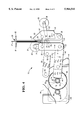
- FIG. 2 is a view looking in the direction of line 2--2 in FIG. 1 and showing a thermal print head and a print platen in initial positions;
- FIG. 3-5 are views similar to FIG. 2 and showing parts in different positions.
- the present invention is directed to a thermal printer apparatus 10 which is embodied in a thermal printer, as shown in FIGS. 1 and 2.
- the thermal printer apparatus 10 includes a movable L-shaped platform 12. One end of a first link 40 is pivotably mounted about a pivot 16 which is attached to the platform 12. The other end of the first link 40 is pivotably mounted about a pivot 42 which is attached to a frame part 44. A set of gear teeth 46 is disposed at a far end edge of the first link 40, as shown in FIG. 2.
- first arm 14 is also pivotably connected about the pivot 16.
- Another arm 15 which is similar to the first arm 14 is pivotably connected about another pivot (not shown) which is attached to the first link 40.
- One end of a second arm 18 is pivotably connected about a pivot 20 which is also attached to the platform 12.
- One leg of the L-shaped platform 12 lies in the plane of FIG. 1 and the other leg of the L-shaped platform 12 lies in the plane of FIG. 2.
- the leg of the L-shaped platform 12 lying in the plane of FIG. 2 has a general shape of a parallelogram, as viewed looking at FIG. 2.
- a print platen 22 having an outer circumferential surface 23 is rotatably mounted about a pivot 21 which is disposed at the other end of the first arm 14.
- a thermal print head 24 having a number of thermal elements 25 is mounted in a known manner at the other end of the second arm 18. The structure and operation of the thermal print head 24 and the thermal elements 25 are well known and, therefore, will not be described.
- the leg of the L-shaped platform 12 lying in the plane of FIG. 1 has a general shape of a rectangle and extends under the print platen 22 and the thermal print head 24, as viewed looking at FIG. 1.
- a pair of brackets 91, 92 define a sheet feed path 26 between the outer circumferential surface 23 of the print platen 22 and the thermal elements 25 of the print head 24.
- the sheet feed path 26 extends in a direction into the page (as viewed looking at FIG. 2).
- a thermal print ribbon (not shown) is guided along portions of the print head 24 in a known manner so that information can be printed onto a sheet 27 which has been positioned in a printing position, such as shown in FIG. 2, along the sheet feed path 26 between the outer circumferential surface 23 of the printer platen 22 and the thermal elements 25 of the print head 24.
- a pair of cams 36 each having opposite facing cam surfaces 37, 38 is located between the first and second arms 14, 18, as shown in FIG. 2.
- the cams 36 are rotatably mounted on a cam shaft 55 which is fixedly attached at one end thereof to the platform 12.
- An actuatable stepper motor 56 is operatively coupled to the cam 36 in a known manner. More specifically, a drive belt 57 is drivingly connected between a pulley 58 disposed on the output shaft of the stepper motor 56 and a pulley 59 disposed on the cam shaft 55.
- a drive belt 57 is drivingly connected between a pulley 58 disposed on the output shaft of the stepper motor 56 and a pulley 59 disposed on the cam shaft 55.
- One end of a second link 50 is pivotably mounted about a pivot 52 which is attached to the platform 12.
- the other end of the second link 50 is pivotably mounted about a pivot 53 which is attached to the frame part 44.
- the first link 40 and the second link 50 extend generally parallel to each other along their longitudinal extents.
- An energizeable drive motor 60 is mounted to the frame part 44, as best shown in FIG. 1.
- the controller 90 controls energization of the drive motor 60.
- the drive motor 60 has an output shaft to which a first gear 62 having a set of gear teeth 64 is attached.
- a second gear 66 has a set of gear teeth 68 which meshingly engages with the set of gear teeth 64 of the first gear 62.
- the second gear 66 is rotatably mounted about a pivot 70 which is attached to the frame part 44.
- a third gear 72 has a set of gear teeth 74 which meshingly engages with the set of gear teeth 46 disposed at the far end edge of the first link 40.
- the third gear 72 is rotatably mounted about the pivot 70, and moves together with the second gear 66 as a unit.
- the second gear 66 and the third gear 72 act as a reduction gear mechanism for the first gear 62.
- the reduction gear mechanism provides a 20:1 reduction.
- the size of the steps of the stepper motor 56 could be selected to match the size of a pixel associated with the print head 24.
- the stepper motor 56 is controlled such that the print platen 22 and the print head 24 move towards or away from each other and the drive motor 60 is controlled such that the platform 12 on which the print platen 22 and the print head 24 are mounted is moved vertically upwards or vertically downwards.
- the print platen 22 and the print head 24 are in positions shown in FIG. 2.
- a sheet feeder 80 (FIG. 1) moves the sheet 27 to be printed on along the sheet feed path 26 to the printing position, as shown in FIG. 2, between the outer circumferential surface 23 of the print platen 22 and the thermal elements 25 of the print head 24.
- the stepper motor 56 is actuated to allow the print platen 22 and the print head 24 to move towards each other under the biasing force of the spring 30 from their positions shown in FIG. 2 to their positions shown in FIG. 3.
- the drive motor 60 is then energized to move the print platen 22 and the print head 24 vertically downwards from their positions shown in FIG. 3 to their positions shown in FIG. 4.
- the thermal elements 25 of the print head 24 are controlled to print information onto the sheet 27.
- the print platen 22 is operatively coupled to a one-way clutch (not shown) which allows the print platen 22 to track in only the vertically downward direction.
- stepper motor 56 is again actuated such that the print platen 22 and the print head 24 move away from each other from their positions shown in FIG. 4 to their positions shown in FIG. 5.
- the drive motor 60 is then energized to move the print platen 22 and the print head 24 vertically upwards from their positions shown in FIG. 5 back to their initial positions shown in FIG. 2.
- the print platen 22 and the print head 24 are now back in their initial positions awaiting the next printing operation to take place.
- thermal printer apparatus 10 including the cam mechanism which moves the print platen 22 and the print head 24 towards and away from each other and the drive mechanism which moves the print platen 22 and the print head 24 in the vertically downwards and vertically upwards directions.
- One advantage is increased throughput of sheets moving along the sheet transport path 26. Throughput is increased since the home position of the print head 24 can be vertically adjusted to a position which is close to start of the printing. This minimizes wasted motion of the print head 24 during printing of information onto a sheet which is in the printing position.
- Another advantage is improved consistency of print quality of the information printed onto sheets moving along the sheet transport path 26. Consistency of print quality is improved since the clamping action on a sheet in the printing position between the print platen 22 and the print head 24 occurs in the central portion of the sheet transport path 26. This minimizes distortion during printing of information onto the sheet which is in the printing position.
Landscapes
- Common Mechanisms (AREA)
Abstract
Description
Claims (4)
Priority Applications (1)
| Application Number | Priority Date | Filing Date | Title |
|---|---|---|---|
| US09/123,692 US5964541A (en) | 1998-07-28 | 1998-07-28 | Thermal printer apparatus |
Applications Claiming Priority (1)
| Application Number | Priority Date | Filing Date | Title |
|---|---|---|---|
| US09/123,692 US5964541A (en) | 1998-07-28 | 1998-07-28 | Thermal printer apparatus |
Publications (1)
| Publication Number | Publication Date |
|---|---|
| US5964541A true US5964541A (en) | 1999-10-12 |
Family
ID=22410284
Family Applications (1)
| Application Number | Title | Priority Date | Filing Date |
|---|---|---|---|
| US09/123,692 Expired - Fee Related US5964541A (en) | 1998-07-28 | 1998-07-28 | Thermal printer apparatus |
Country Status (1)
| Country | Link |
|---|---|
| US (1) | US5964541A (en) |
Cited By (38)
| Publication number | Priority date | Publication date | Assignee | Title |
|---|---|---|---|---|
| EP1321296A2 (en) | 2001-12-18 | 2003-06-25 | Ncr International Inc. | Direct thermal printer |
| EP1321304A2 (en) | 2001-12-18 | 2003-06-25 | Ncr International Inc. | Dual-sided imaging element |
| US6736557B2 (en) | 2002-09-05 | 2004-05-18 | Lexmark International, Inc. | Printhead gap adjustment mechanism for an imaging apparatus |
| US20060033802A1 (en) * | 2004-08-16 | 2006-02-16 | Samsung Electronics Co., Ltd. | Thermal type image forming apparatus and method of removing jammed medium therefrom |
| EP1655140A1 (en) * | 2004-11-06 | 2006-05-10 | Samsung Electronics Co., Ltd. | Thermal Printer |
| US20060289633A1 (en) * | 2005-06-23 | 2006-12-28 | Ncr Corporation | Receipts having dual-sided thermal printing |
| US20070120942A1 (en) * | 2005-11-30 | 2007-05-31 | Ncr Corporation | Dual-sided two color thermal printing |
| US20070134039A1 (en) * | 2005-12-08 | 2007-06-14 | Ncr Corporation | Dual-sided thermal printing |
| US20070206982A1 (en) * | 2006-03-01 | 2007-09-06 | Ncr Corporation | Thermal indicators |
| US20070207926A1 (en) * | 2006-03-03 | 2007-09-06 | Ncr Corporation | Two-sided thermal paper |
| US20070211099A1 (en) * | 2006-03-07 | 2007-09-13 | Lyons Dale R | Two-sided thermal print sensing |
| US20070211134A1 (en) * | 2006-03-07 | 2007-09-13 | Ncr Corporation | Direct thermal and inkjet dual-sided printing |
| US20070213214A1 (en) * | 2006-03-07 | 2007-09-13 | Roth Joseph D | Two-sided thermal wrap around label |
| US20070210572A1 (en) * | 2006-03-07 | 2007-09-13 | Ncr Corporation | Dual-sided thermal security features |
| US20070212515A1 (en) * | 2006-03-07 | 2007-09-13 | Ncr Corporation | Dual-sided thermal form card |
| US20070211135A1 (en) * | 2005-12-08 | 2007-09-13 | Richard Moreland | Dual-sided two-ply direct thermal image element |
| US20070211132A1 (en) * | 2006-03-07 | 2007-09-13 | Lyons Dale R | Two-sided thermal print configurations |
| US20070211094A1 (en) * | 2006-03-07 | 2007-09-13 | Ncr Corporation | Dual-sided thermal pharmacy script printing |
| US20070213213A1 (en) * | 2006-03-07 | 2007-09-13 | Ncr Corporation | UV and thermal guard |
| US20070213215A1 (en) * | 2006-03-07 | 2007-09-13 | Ncr Corporation | Multi-color dual-sided thermal printing |
| US20070212146A1 (en) * | 2005-12-08 | 2007-09-13 | Dale Lyons | Two-sided thermal print switch |
| US20070244005A1 (en) * | 2006-03-07 | 2007-10-18 | Ncr Corporation | Multisided thermal media combinations |
| US20080297583A1 (en) * | 2007-06-04 | 2008-12-04 | Dale Lyons | Two-sided thermal print command |
| US20080316534A1 (en) * | 2007-06-20 | 2008-12-25 | Mcgarry Colman | Two-sided print data splitting |
| US20090017237A1 (en) * | 2007-07-12 | 2009-01-15 | Rawlings Timothy W | Two-sided thermal transfer ribbon |
| US20090015647A1 (en) * | 2007-07-12 | 2009-01-15 | Rawlings Timothy W | Two-side thermal printer |
| US20090058892A1 (en) * | 2007-08-31 | 2009-03-05 | Ncr Corporation | Direct thermal and inkjet dual-sided printing |
| US20090060606A1 (en) * | 2007-08-31 | 2009-03-05 | Ncr Corporation | Controlled fold document delivery |
| US20090089172A1 (en) * | 2007-09-28 | 2009-04-02 | Quinlan Mark D | Multi-lingual two-sided printing |
| US7589752B2 (en) | 2005-01-15 | 2009-09-15 | Ncr Corporation | Two-sided thermal printing |
| WO2009142927A1 (en) * | 2008-05-23 | 2009-11-26 | Fujifilm Corporation | Adjustable printhead mounting |
| US7839425B2 (en) | 2008-09-17 | 2010-11-23 | Ncr Corporation | Method of controlling thermal printing |
| US8211826B2 (en) | 2007-07-12 | 2012-07-03 | Ncr Corporation | Two-sided thermal media |
| US8462184B2 (en) | 2005-12-08 | 2013-06-11 | Ncr Corporation | Two-sided thermal printer control |
| US8848010B2 (en) | 2007-07-12 | 2014-09-30 | Ncr Corporation | Selective direct thermal and thermal transfer printing |
| JP2015107622A (en) * | 2013-12-06 | 2015-06-11 | 日立オムロンターミナルソリューションズ株式会社 | Thermal head printing mechanism |
| CN105383183A (en) * | 2014-09-02 | 2016-03-09 | 精工电子有限公司 | Printing unit and printer |
| TWI648169B (en) * | 2014-09-02 | 2019-01-21 | 日商精工電子有限公司 | Printing unit and printer |
Citations (11)
| Publication number | Priority date | Publication date | Assignee | Title |
|---|---|---|---|---|
| US3810192A (en) * | 1972-06-29 | 1974-05-07 | Copal Co Ltd | Thermosensitive line printer |
| US4560292A (en) * | 1983-03-25 | 1985-12-24 | Kabushiki Kaisha Ishida Koki Seisakusho | Printer comprising spring biased print head and roller platen |
| US4815871A (en) * | 1986-11-14 | 1989-03-28 | Varitronic Systems, Inc. | Head control apparatus |
| US4818126A (en) * | 1983-12-14 | 1989-04-04 | Ncr Canada Ltd - Ncr Canada Ltee | Method and apparatus for thermally printing data in special fonts on documents like checks |
| US4952084A (en) * | 1987-08-06 | 1990-08-28 | Alps Electric Co., Ltd. | Head position controller for thermal printer |
| US5071266A (en) * | 1987-09-29 | 1991-12-10 | Sharp Kabushiki Kaisha | Head engagement mechanism for thermal recording apparatus |
| US5118208A (en) * | 1990-07-13 | 1992-06-02 | Tokyo Electric Co., Ltd. | Printer with interlocked movable platen and presser |
| US5137378A (en) * | 1991-05-22 | 1992-08-11 | Tohoku Ricoh Co., Ltd. | Thermal printer having ribbon conserving mechanism |
| US5265966A (en) * | 1993-03-05 | 1993-11-30 | Rimage Corporation | Printer linkage |
| US5445460A (en) * | 1993-02-26 | 1995-08-29 | Sony Corporation | Pressure-contact device for applying print head onto platen of printer |
| US5555009A (en) * | 1993-01-22 | 1996-09-10 | Gerber Scientific Products, Inc. | Printing apparatus with pressure regulation |
-
1998
- 1998-07-28 US US09/123,692 patent/US5964541A/en not_active Expired - Fee Related
Patent Citations (11)
| Publication number | Priority date | Publication date | Assignee | Title |
|---|---|---|---|---|
| US3810192A (en) * | 1972-06-29 | 1974-05-07 | Copal Co Ltd | Thermosensitive line printer |
| US4560292A (en) * | 1983-03-25 | 1985-12-24 | Kabushiki Kaisha Ishida Koki Seisakusho | Printer comprising spring biased print head and roller platen |
| US4818126A (en) * | 1983-12-14 | 1989-04-04 | Ncr Canada Ltd - Ncr Canada Ltee | Method and apparatus for thermally printing data in special fonts on documents like checks |
| US4815871A (en) * | 1986-11-14 | 1989-03-28 | Varitronic Systems, Inc. | Head control apparatus |
| US4952084A (en) * | 1987-08-06 | 1990-08-28 | Alps Electric Co., Ltd. | Head position controller for thermal printer |
| US5071266A (en) * | 1987-09-29 | 1991-12-10 | Sharp Kabushiki Kaisha | Head engagement mechanism for thermal recording apparatus |
| US5118208A (en) * | 1990-07-13 | 1992-06-02 | Tokyo Electric Co., Ltd. | Printer with interlocked movable platen and presser |
| US5137378A (en) * | 1991-05-22 | 1992-08-11 | Tohoku Ricoh Co., Ltd. | Thermal printer having ribbon conserving mechanism |
| US5555009A (en) * | 1993-01-22 | 1996-09-10 | Gerber Scientific Products, Inc. | Printing apparatus with pressure regulation |
| US5445460A (en) * | 1993-02-26 | 1995-08-29 | Sony Corporation | Pressure-contact device for applying print head onto platen of printer |
| US5265966A (en) * | 1993-03-05 | 1993-11-30 | Rimage Corporation | Printer linkage |
Cited By (77)
| Publication number | Priority date | Publication date | Assignee | Title |
|---|---|---|---|---|
| EP1829701A1 (en) | 2001-12-18 | 2007-09-05 | Ncr International Inc. | Dual-sided imaging element |
| EP1321304A2 (en) | 2001-12-18 | 2003-06-25 | Ncr International Inc. | Dual-sided imaging element |
| US6759366B2 (en) | 2001-12-18 | 2004-07-06 | Ncr Corporation | Dual-sided imaging element |
| US6784906B2 (en) | 2001-12-18 | 2004-08-31 | Ncr Corporation | Direct thermal printer |
| EP1321296A2 (en) | 2001-12-18 | 2003-06-25 | Ncr International Inc. | Direct thermal printer |
| US6736557B2 (en) | 2002-09-05 | 2004-05-18 | Lexmark International, Inc. | Printhead gap adjustment mechanism for an imaging apparatus |
| EP1627745A1 (en) * | 2004-08-16 | 2006-02-22 | Samsung Electronics Co., Ltd. | Image forming apparatus |
| US7333123B2 (en) | 2004-08-16 | 2008-02-19 | Samsung Electronics Co., Ltd. | Thermal type image forming apparatus and method of removing jammed medium therefrom |
| US20060033802A1 (en) * | 2004-08-16 | 2006-02-16 | Samsung Electronics Co., Ltd. | Thermal type image forming apparatus and method of removing jammed medium therefrom |
| EP1655140A1 (en) * | 2004-11-06 | 2006-05-10 | Samsung Electronics Co., Ltd. | Thermal Printer |
| US20060098081A1 (en) * | 2004-11-06 | 2006-05-11 | Samsung Electronics Co., Ltd. | Thermal printer |
| US7365761B2 (en) | 2004-11-06 | 2008-04-29 | Samsung Electronics Co., Ltd. | Thermal printer |
| CN100439110C (en) * | 2004-11-06 | 2008-12-03 | 三星电子株式会社 | thermal printer |
| US7589752B2 (en) | 2005-01-15 | 2009-09-15 | Ncr Corporation | Two-sided thermal printing |
| US20060289633A1 (en) * | 2005-06-23 | 2006-12-28 | Ncr Corporation | Receipts having dual-sided thermal printing |
| US20070120942A1 (en) * | 2005-11-30 | 2007-05-31 | Ncr Corporation | Dual-sided two color thermal printing |
| US7777770B2 (en) | 2005-12-08 | 2010-08-17 | Ncr Corporation | Dual-sided two-ply direct thermal image element |
| US20090290923A9 (en) * | 2005-12-08 | 2009-11-26 | Dale Lyons | Two-sided thermal print switch |
| US20070211135A1 (en) * | 2005-12-08 | 2007-09-13 | Richard Moreland | Dual-sided two-ply direct thermal image element |
| US8462184B2 (en) | 2005-12-08 | 2013-06-11 | Ncr Corporation | Two-sided thermal printer control |
| US8721202B2 (en) | 2005-12-08 | 2014-05-13 | Ncr Corporation | Two-sided thermal print switch |
| US20070212146A1 (en) * | 2005-12-08 | 2007-09-13 | Dale Lyons | Two-sided thermal print switch |
| US20070134039A1 (en) * | 2005-12-08 | 2007-06-14 | Ncr Corporation | Dual-sided thermal printing |
| US8083423B2 (en) | 2006-03-01 | 2011-12-27 | Ncr Corporation | Thermal indicators |
| US20070206982A1 (en) * | 2006-03-01 | 2007-09-06 | Ncr Corporation | Thermal indicators |
| US8114812B2 (en) | 2006-03-03 | 2012-02-14 | Ncr Corporation | Two-sided thermal paper |
| US20070207926A1 (en) * | 2006-03-03 | 2007-09-06 | Ncr Corporation | Two-sided thermal paper |
| US20070213213A1 (en) * | 2006-03-07 | 2007-09-13 | Ncr Corporation | UV and thermal guard |
| US20070211132A1 (en) * | 2006-03-07 | 2007-09-13 | Lyons Dale R | Two-sided thermal print configurations |
| US8067335B2 (en) | 2006-03-07 | 2011-11-29 | Ncr Corporation | Multisided thermal media combinations |
| US20070213215A1 (en) * | 2006-03-07 | 2007-09-13 | Ncr Corporation | Multi-color dual-sided thermal printing |
| US9024986B2 (en) | 2006-03-07 | 2015-05-05 | Ncr Corporation | Dual-sided thermal pharmacy script printing |
| US8043993B2 (en) | 2006-03-07 | 2011-10-25 | Ncr Corporation | Two-sided thermal wrap around label |
| US8670009B2 (en) | 2006-03-07 | 2014-03-11 | Ncr Corporation | Two-sided thermal print sensing |
| US20070211094A1 (en) * | 2006-03-07 | 2007-09-13 | Ncr Corporation | Dual-sided thermal pharmacy script printing |
| US8367580B2 (en) | 2006-03-07 | 2013-02-05 | Ncr Corporation | Dual-sided thermal security features |
| US8252717B2 (en) | 2006-03-07 | 2012-08-28 | Ncr Corporation | Dual-sided two-ply direct thermal image element |
| US8222184B2 (en) | 2006-03-07 | 2012-07-17 | Ncr Corporation | UV and thermal guard |
| US20070244005A1 (en) * | 2006-03-07 | 2007-10-18 | Ncr Corporation | Multisided thermal media combinations |
| US20090185021A9 (en) * | 2006-03-07 | 2009-07-23 | Lyons Dale R | Two-sided thermal print configurations |
| US20070212515A1 (en) * | 2006-03-07 | 2007-09-13 | Ncr Corporation | Dual-sided thermal form card |
| US20070210572A1 (en) * | 2006-03-07 | 2007-09-13 | Ncr Corporation | Dual-sided thermal security features |
| US8173575B2 (en) | 2006-03-07 | 2012-05-08 | Ncr Corporation | Dual-sided thermal form card |
| US7710442B2 (en) | 2006-03-07 | 2010-05-04 | Ncr Corporation | Two-sided thermal print configurations |
| US7764299B2 (en) | 2006-03-07 | 2010-07-27 | Ncr Corporation | Direct thermal and inkjet dual-sided printing |
| US20070213214A1 (en) * | 2006-03-07 | 2007-09-13 | Roth Joseph D | Two-sided thermal wrap around label |
| US20100253716A1 (en) * | 2006-03-07 | 2010-10-07 | Ncr Corporation | Direct thermal and inkjet dual-sided printing |
| US20070211134A1 (en) * | 2006-03-07 | 2007-09-13 | Ncr Corporation | Direct thermal and inkjet dual-sided printing |
| US20070211099A1 (en) * | 2006-03-07 | 2007-09-13 | Lyons Dale R | Two-sided thermal print sensing |
| WO2008097239A2 (en) | 2007-02-08 | 2008-08-14 | Ncr Corporation | Dual-sided thermal form card |
| US8194107B2 (en) | 2007-06-04 | 2012-06-05 | Ncr Corporation | Two-sided thermal print command |
| US20080297583A1 (en) * | 2007-06-04 | 2008-12-04 | Dale Lyons | Two-sided thermal print command |
| US8576436B2 (en) | 2007-06-20 | 2013-11-05 | Ncr Corporation | Two-sided print data splitting |
| US20080316534A1 (en) * | 2007-06-20 | 2008-12-25 | Mcgarry Colman | Two-sided print data splitting |
| US8211826B2 (en) | 2007-07-12 | 2012-07-03 | Ncr Corporation | Two-sided thermal media |
| US20090015647A1 (en) * | 2007-07-12 | 2009-01-15 | Rawlings Timothy W | Two-side thermal printer |
| US7531224B2 (en) | 2007-07-12 | 2009-05-12 | Ncr Corporation | Two-sided thermal transfer ribbon |
| US9056488B2 (en) | 2007-07-12 | 2015-06-16 | Ncr Corporation | Two-side thermal printer |
| US8848010B2 (en) | 2007-07-12 | 2014-09-30 | Ncr Corporation | Selective direct thermal and thermal transfer printing |
| US20090017237A1 (en) * | 2007-07-12 | 2009-01-15 | Rawlings Timothy W | Two-sided thermal transfer ribbon |
| US20090060606A1 (en) * | 2007-08-31 | 2009-03-05 | Ncr Corporation | Controlled fold document delivery |
| US8182161B2 (en) | 2007-08-31 | 2012-05-22 | Ncr Corporation | Controlled fold document delivery |
| US20090058892A1 (en) * | 2007-08-31 | 2009-03-05 | Ncr Corporation | Direct thermal and inkjet dual-sided printing |
| US20090089172A1 (en) * | 2007-09-28 | 2009-04-02 | Quinlan Mark D | Multi-lingual two-sided printing |
| US8504427B2 (en) | 2007-09-28 | 2013-08-06 | Ncr Corporation | Multi-lingual two-sided printing |
| WO2009142927A1 (en) * | 2008-05-23 | 2009-11-26 | Fujifilm Corporation | Adjustable printhead mounting |
| US8425007B2 (en) | 2008-05-23 | 2013-04-23 | Fujifilm Corporation | Adjustable printhead mounting |
| US20110109696A1 (en) * | 2008-05-23 | 2011-05-12 | Fujifilm Corporation | Adjustable printhead mounting |
| US8314821B2 (en) | 2008-09-17 | 2012-11-20 | Ncr Corporation | Method of controlling thermal printing |
| US20110063394A1 (en) * | 2008-09-17 | 2011-03-17 | Morrison Randall L | Method of controlling thermal printing |
| US7839425B2 (en) | 2008-09-17 | 2010-11-23 | Ncr Corporation | Method of controlling thermal printing |
| JP2015107622A (en) * | 2013-12-06 | 2015-06-11 | 日立オムロンターミナルソリューションズ株式会社 | Thermal head printing mechanism |
| CN105383183A (en) * | 2014-09-02 | 2016-03-09 | 精工电子有限公司 | Printing unit and printer |
| EP3002130A3 (en) * | 2014-09-02 | 2016-11-02 | Seiko Instruments Inc. | Printing unit and printer |
| US9604474B2 (en) | 2014-09-02 | 2017-03-28 | Seiko Instruments Inc. | Printing unit and printer |
| CN105383183B (en) * | 2014-09-02 | 2018-01-16 | 精工电子有限公司 | Print unit and printer |
| TWI648169B (en) * | 2014-09-02 | 2019-01-21 | 日商精工電子有限公司 | Printing unit and printer |
Similar Documents
| Publication | Publication Date | Title |
|---|---|---|
| US5964541A (en) | Thermal printer apparatus | |
| US4752786A (en) | Single motor multi-function drive control recorder | |
| US4848226A (en) | Material gripping arrangement for stencil printing machine | |
| JPS6273978A (en) | printing device | |
| US5378071A (en) | Video printer | |
| JPH0418558B2 (en) | ||
| EP0556066A2 (en) | Print head movement control | |
| JPH0534937Y2 (en) | ||
| JP3655822B2 (en) | Inkjet printer | |
| JP3776785B2 (en) | Printer | |
| US6011572A (en) | Head up-down mechanism in printer | |
| JPS6154972A (en) | thermal printer | |
| JP3551377B2 (en) | Inkjet printer | |
| JPH079647Y2 (en) | Thermal transfer printer | |
| JPH0357473Y2 (en) | ||
| JP2503306Y2 (en) | Paper guide device | |
| JPS59209173A (en) | Printing device paper feed mechanism | |
| JPS6017330Y2 (en) | serial printer | |
| KR100255354B1 (en) | A paper separator with a second pressure controller for feeding paper | |
| JPH08207390A (en) | Ink jet printer | |
| JPS6340675B2 (en) | ||
| JPH03120069A (en) | Thermal head driving mechanism for printer | |
| JPH0796650A (en) | Printer | |
| JPH0712012Y2 (en) | Thermal printer | |
| JP2543726Y2 (en) | Print head drive mechanism |
Legal Events
| Date | Code | Title | Description |
|---|---|---|---|
| AS | Assignment |
Owner name: NCR CORPORATION, OHIO Free format text: ASSIGNMENT OF ASSIGNORS INTEREST;ASSIGNORS:MURISON, ALEXANDER S.;MARSHALL, GARY R.;REEL/FRAME:009364/0755 Effective date: 19980727 |
|
| LAPS | Lapse for failure to pay maintenance fees | ||
| LAPS | Lapse for failure to pay maintenance fees |
Free format text: PATENT EXPIRED FOR FAILURE TO PAY MAINTENANCE FEES (ORIGINAL EVENT CODE: EXP.); ENTITY STATUS OF PATENT OWNER: LARGE ENTITY |
|
| STCH | Information on status: patent discontinuation |
Free format text: PATENT EXPIRED DUE TO NONPAYMENT OF MAINTENANCE FEES UNDER 37 CFR 1.362 |
|
| FP | Lapsed due to failure to pay maintenance fee |
Effective date: 20031012 |
|
| AS | Assignment |
Owner name: CITIBANK, N.A., NEW YORK Free format text: SECURITY INTEREST;ASSIGNOR:NCR ATLEOS CORPORATION;REEL/FRAME:065331/0297 Effective date: 20230927 |
|
| AS | Assignment |
Owner name: BANK OF AMERICA, N.A., AS ADMINISTRATIVE AGENT, NORTH CAROLINA Free format text: SECURITY INTEREST;ASSIGNORS:NCR ATLEOS CORPORATION;CARDTRONICS USA, LLC;REEL/FRAME:065346/0367 Effective date: 20231016 |
|
| AS | Assignment |
Owner name: CITIBANK, N.A., NEW YORK Free format text: CORRECTIVE ASSIGNMENT TO CORRECT THE DOCUMENT DATE AND REMOVE THE OATH/DECLARATION (37 CFR 1.63) PREVIOUSLY RECORDED AT REEL: 065331 FRAME: 0297. ASSIGNOR(S) HEREBY CONFIRMS THE SECURITY INTEREST;ASSIGNOR:NCR ATLEOS CORPORATION;REEL/FRAME:065627/0332 Effective date: 20231016 |
|
| AS | Assignment |
Owner name: NCR VOYIX CORPORATION, GEORGIA Free format text: CHANGE OF NAME;ASSIGNOR:NCR CORPORATION;REEL/FRAME:067578/0417 Effective date: 20231013 Owner name: NCR ATLEOS CORPORATION, GEORGIA Free format text: ASSIGNMENT OF ASSIGNORS INTEREST;ASSIGNOR:NCR VOYIX CORPORATION;REEL/FRAME:067590/0109 Effective date: 20231016 |
|
| AS | Assignment |
Owner name: BANK OF AMERICA, N.A., AS ADMINISTRATIVE AGENT, NORTH CAROLINA Free format text: CORRECTIVE ASSIGNMENT TO CORRECT THE THE PROPERTIES SECTION BY INCLUDING IT WITH TEN PREVIOUSLY OMITTED PROPERTY NUMBERS PREVIOUSLY RECORDED ON REEL 65346 FRAME 367. ASSIGNOR(S) HEREBY CONFIRMS THE SECURITY INTEREST;ASSIGNORS:NCR ATLEOS CORPORATION;CARDTRONICS USA, LLC;REEL/FRAME:072445/0072 Effective date: 20231016 |