EP0607480B1 - Method and apparatus for producing laminated wooden beams and other wooden products from continuously finger jointed wooden boards - Google Patents
Method and apparatus for producing laminated wooden beams and other wooden products from continuously finger jointed wooden boards Download PDFInfo
- Publication number
- EP0607480B1 EP0607480B1 EP19930100716 EP93100716A EP0607480B1 EP 0607480 B1 EP0607480 B1 EP 0607480B1 EP 19930100716 EP19930100716 EP 19930100716 EP 93100716 A EP93100716 A EP 93100716A EP 0607480 B1 EP0607480 B1 EP 0607480B1
- Authority
- EP
- European Patent Office
- Prior art keywords
- laminated
- glue
- wood
- press
- boards
- Prior art date
- Legal status (The legal status is an assumption and is not a legal conclusion. Google has not performed a legal analysis and makes no representation as to the accuracy of the status listed.)
- Expired - Lifetime
Links
Images


Classifications
-
- B—PERFORMING OPERATIONS; TRANSPORTING
- B27—WORKING OR PRESERVING WOOD OR SIMILAR MATERIAL; NAILING OR STAPLING MACHINES IN GENERAL
- B27M—WORKING OF WOOD NOT PROVIDED FOR IN SUBCLASSES B27B - B27L; MANUFACTURE OF SPECIFIC WOODEN ARTICLES
- B27M1/00—Working of wood not provided for in subclasses B27B - B27L, e.g. by stretching
- B27M1/08—Working of wood not provided for in subclasses B27B - B27L, e.g. by stretching by multi-step processes
-
- B—PERFORMING OPERATIONS; TRANSPORTING
- B27—WORKING OR PRESERVING WOOD OR SIMILAR MATERIAL; NAILING OR STAPLING MACHINES IN GENERAL
- B27M—WORKING OF WOOD NOT PROVIDED FOR IN SUBCLASSES B27B - B27L; MANUFACTURE OF SPECIFIC WOODEN ARTICLES
- B27M3/00—Manufacture or reconditioning of specific semi-finished or finished articles
- B27M3/0013—Manufacture or reconditioning of specific semi-finished or finished articles of composite or compound articles
- B27M3/002—Manufacture or reconditioning of specific semi-finished or finished articles of composite or compound articles characterised by oblong elements connected at their ends
-
- B—PERFORMING OPERATIONS; TRANSPORTING
- B27—WORKING OR PRESERVING WOOD OR SIMILAR MATERIAL; NAILING OR STAPLING MACHINES IN GENERAL
- B27M—WORKING OF WOOD NOT PROVIDED FOR IN SUBCLASSES B27B - B27L; MANUFACTURE OF SPECIFIC WOODEN ARTICLES
- B27M3/00—Manufacture or reconditioning of specific semi-finished or finished articles
- B27M3/0013—Manufacture or reconditioning of specific semi-finished or finished articles of composite or compound articles
- B27M3/006—Manufacture or reconditioning of specific semi-finished or finished articles of composite or compound articles characterised by oblong elements connected both laterally and at their ends
Definitions
- the invention relates to a device and a method for producing plywood bodies from individual plywood elements glued together.
- Wide glulam components also need wide individual boards. Otherwise you have to glue the individual boards endlessly in their width and then cut out this wide area with a cross-cut saw in the desired width and glue the obtained sections lengthways. In this way, you can produce any width for glulam beams. However, this production is expensive. Wide boards of approx. 250 to 300 mm are hardly anymore cut by sawmills and if so, these boards are much more expensive. According to DIN 1.052, wide boards would have to be scored on both sides before gluing, so that the residual stresses remain ineffective. This process is complex. The wide board of the Stammitte cannot be used because of the high internal stress. The forest industry cannot supply these quantities and widths because intensive use means that the forest is cut earlier.
- the object of the invention is to produce normal glued laminated timber of different widths with a glulam press without emptying the press, economically producing excess widths from several narrow boards and large upper and lower chords and gluing these statically favorably at large distances with smaller cross sections, and furthermore the pressing pressure offset from 90 ° to effect a surface gluing for double T, To enable box girder and other profiles. Gluing should be done quickly. A combination with other materials should be possible in order to apply or introduce layers for fire protection, sound and heat insulation, liquid insulation and others.
- a package of different widths of the multi-lane press can be processed to the length of the end product.
- Boards of different widths can be stacked in height and easily accessed as needed.
- the gluing device for the production of the glulam beams is closed, the width can be changed against spring force and can be heated.
- the individual components or the glue can be heated for faster setting.
- the gluing device is suitable for holding several boards.
- the conventional method of roller transport is not suitable for achieving a continuous speed of the glue application, because a resilient sealing of the board guide by the gluing device results in an uneven speed, and thus an associated uneven amount of glue application. Therefore, the boards are inevitably transported on a conveyor belt.
- the gluing device is set by a resilient stop of a pressure cylinder to the width of the boards to be glued, as is the height of the slit-shaped glue discharge openings by a slide.
- the assembled boards to be glued are turned in every second layer by 180 ° to overlap the different ones Get board widths.
- the boards of the same or different width specified with glue are placed in the plywood press, positioned and pressed.
- the press has a further pressure unit, which takes over the backflow protection and a sliding pressure unit for maintaining the glue pressure when the counter pressure is removed.
- the two pressure units acting on one level have a much higher pressure than would be required for gluing glulam beams. This favors the manufacture of the box girder and other profiles.
- the first rigid pressure unit can therefore be used for gluing the lower belt and the second movable for the upper belt. In this way you can economically produce I-profiles and other suitable surface gluing.
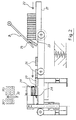
- Fig. 1 The construction of a plywood press designated 1 has a push-in cylinder 3 provided with a heatable pressure piece 2 for the boards 27 to be glued, which counteracts a counter-pressure cylinder 4 which can be fixed in individual positions in bores 5 with the locking bolt 6 of a working cylinder 7.
- a second printing unit (10) is in the direction of arrows 12 and 13 on rollers 14 and on the pulley 15 and the drive wheel 16 moving belt horizontally.
- the last boards 27 of a glulam beam width are not specified with glue.
- the piston stroke of the cylinder 4 is advantageously as long as the max. glulam width to be produced. If an empty joint indicates the end of the width, then, or a few inserts later, the pressure piece 11 goes into active position through the hydraulic cylinder of the printing unit 10. The pressure piece 20 is withdrawn by the cylinder 4 and the glued glulam beam is raised and transported away for surface treatment in a known manner. The pressure is maintained between the pressure units 9 and 10 and the connection 8 between the pressure pieces 11 absorbs the forces acting in the direction of the arrows 12 and 13.
- the boards 27 can be inserted further, the adjustable counterforce is taken over by the pressure unit 10 through friction until cylinder 4 with the pressure piece is in the active position. Friction is only possible if the glue has set in the glulam beam. Due to the possible deformation of the individual boards, the glue joint would be destroyed. Therefore, the pressure piece 11 of the printing unit 10 must initially take over the counter pressure. Since the glulam beams are manufactured in different widths, the mobile printing unit is brought into the required position by the driver in the direction of arrow 12 or 13 by the drive. On the construction 1, the perforated rail with the holes 5 is attached, where the compressed air cylinders 7 lock the bolts 6 in the front flange of the impression cylinder 4.
- each When pressed in two channels, as shown in FIG. 10, by a film 18 in boards 19 which are separated from one another to prevent gluing, each is pressed by an insertion cylinder 3 and a common counter-pressure piece 20 of the counter-pressure cylinder 4.
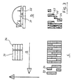
- FIG. 2 A stack of boards of the same width is pushed on a structure 21 in the direction of arrow 22 and separated over an edge 23, a rotatable stop 24 preventing tipping.
- the isolated boards 25, 26, 27 are conveyed to a stop 28 of a press shoe 29 by a belt into the position of the transverse press web 30, on which the boards are connected to form an endless web with glue-specified finger joints at their ends.
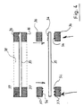
- FIG. 3 A wider and a narrower board 31, 32 are taken from stacks 33, 34 (FIG. 3a) sorted according to their width, put together, the second layer being turned through 180 ° (FIG. 3a) in order to align the joints to avoid the plywood beam.
- the assembly of a plywood beam from boards of three different widths is shown in Fig.3c.
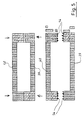
- Fig. 4 Shown is a plate 35 made of glue-capable material, on which the plywood supports 36 and 37 according to the invention are glued on both sides of a space 38 that can be filled with insulating material.
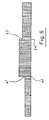
- FIG. 5 A hollow box profile is shown, which is glued together from two plywood beams 39, 40 produced according to the invention.
- Fig. 6 Shown is the profile of a plywood carrier made of boards of different widths, which can be separated at the unglued joints 41, 42 and 43, 44.
- the gluing device is shown, with which the boards can be glued in accordance with FIG. 1 before being introduced into the press.
- the boards 45 are pulled through the stop 46 on a conveyor belt under the gluing device 47.
- the gluing device 47 has a housing made of walls 48, 49, 50 with a fixed side wall 51 and a movable cover 52.
- the wall 50 is provided on its lower edge with incisions 53 for the application of the glue in parallel strands, which can be covered in an adjustable manner by a slide 56 adjustable by rollers 55 for metering the glue 54.
- the side wall 57 of the housing of the gluing device 47 can be displaced with respect to the side wall 51 after the respective board to be treated by the working cylinder 58 against spring action and thus serves as a stop on the inserted board.
- Tubes 59 and 60 for each glue component are arranged on the top of the wall 48 and have glue outlet openings 61 and 62.
- the glue supply pipes 63 and 64 can be moved together with the side wall 47 and lie within the pipes 59 and 60, whereby they seal the glue outlet openings 61 and 62 lying outside the wall 57, respectively.
Description
Die Erfindung betrifft eine Vorrichtung und ein Verfahren zur Herstellung von Schichtholzkörpern aus einzelnen miteinander verleimten Schichtholzelementen.The invention relates to a device and a method for producing plywood bodies from individual plywood elements glued together.
Breite Bauteile aus Brettschichtholz benötigen ebenso breite einzelne Bretter. Andernfalls muß man die einzelnen Bretter in deren Breite endlos verleimen und diese breite Fläche dann durch eine Querkreissäge in der gewünschten Breite ausschneiden und die erzielten Abschnitte längs verleimen. Auf diese Art kann man jede Breite für Brettschichtholzträger herstellen. Diese Herstellung ist aber kostspielig. Breite Bretter von ca. 250 bis 300 mm werden kaum noch von Sägewerken zugeschnitten und wenn, dann sind diese Bretter viel teurer. Breite Bretter müßten nach DIN 1.052 vor der Verleimung zweiseitig geritzt werden, damit die Eigenspannungen wirkungslos bleiben. Dieses Verfahren ist aufwendig. Das breite Brett der Stammitte kann man wegen der hohen Eigenspannung nicht verwenden. Die Forstindustrie kann diese Mengen und Breiten nicht liefern, weil durch die intensive Nutzung der Wald früher geschlagen wird. Wegen der volkswirtschaftlich hohen Bedeutung wird eine sparsame und bessere Holzausnutzung gesucht mit der Möglichkeit, das Brettschichtholz statisch besser zu verwerten, wie es zum Beispiel bei der Stahlindustrie durch Vierkantprofile, Doppel-T oder mit anderen Profilen möglich ist, die automatisch ohne viel handling hergestellt werden können. Dadurch können mit derselben Menge Holz mehr tragende Bauteile gefertigt werden, als mit dem Vollholz-Brettschichtholzträger möglich ist. Derartige Profile können jedoch nicht mit den auf dem Markt befindlichen Maschinen, Beleimungsangaben und -vorrichtungen hergestellt werden, besonders auch deshalb nicht, weil die zur Verwendung kommenden Leime eine Abbindzeit von 8 bis 10 Stunden bei Raumtemperatur haben.Wide glulam components also need wide individual boards. Otherwise you have to glue the individual boards endlessly in their width and then cut out this wide area with a cross-cut saw in the desired width and glue the obtained sections lengthways. In this way, you can produce any width for glulam beams. However, this production is expensive. Wide boards of approx. 250 to 300 mm are hardly anymore cut by sawmills and if so, these boards are much more expensive. According to DIN 1.052, wide boards would have to be scored on both sides before gluing, so that the residual stresses remain ineffective. This process is complex. The wide board of the Stammitte cannot be used because of the high internal stress. The forest industry cannot supply these quantities and widths because intensive use means that the forest is cut earlier. Because of the high economic importance, economical and better use of wood is sought with the possibility of using the glulam better statically, as is possible, for example, in the steel industry with square profiles, double-T or with other profiles that are automatically produced without much handling can. This means that more load-bearing components can be produced with the same amount of wood than is possible with the solid wood glulam beam. However, such profiles cannot be produced with the machines, gluing details and devices on the market, especially not because the glues used have a setting time of 8 to 10 hours at room temperature.
Aufgabe der Erfindung ist es, mit einer Brettschichtholzpresse normale Brettschichthölzer unterschiedlicher Breite herzustellen, ohne die Presse zu entleeren, Überbreiten aus mehreren schmalen Brettern und große Ober- und Untergurte wirschaftlich herzustellen sowie diese statisch günstig in großen Abständen mit geringeren Querschnitten zu verleimen, ferner den Preßdruck von 90° versetzt in Wirkung zu bringen, um eine Flächenverleimung für Doppel-T, Hohlkasten und sonstige Profile zu ermöglichen. Die Verleimug soll schnell erfolgen. Eine Kombination mit anderen Werkstoffen soll möglich sein, um Schichten für Feuerschutz, Schall- und Wärmedämmung, Flüssigkeitsisolierung und u.a. an- oder einzubringen.The object of the invention is to produce normal glued laminated timber of different widths with a glulam press without emptying the press, economically producing excess widths from several narrow boards and large upper and lower chords and gluing these statically favorably at large distances with smaller cross sections, and furthermore the pressing pressure offset from 90 ° to effect a surface gluing for double T, To enable box girder and other profiles. Gluing should be done quickly. A combination with other materials should be possible in order to apply or introduce layers for fire protection, sound and heat insulation, liquid insulation and others.
Bei paketweiser Verarbeitung in der Keilzinkenfräse kann je ein Paket verschiedener Breiten der mehrbahnigen Presse entsprechender Ausführung zu den Längen des Endproduktes verarbeitet werden. Bretter verschiedener Breite können in die Höhe gestapelt und leicht nach Bedarf abgerufen werden.With processing in the finger jointing machine in packages, a package of different widths of the multi-lane press can be processed to the length of the end product. Boards of different widths can be stacked in height and easily accessed as needed.
Die Beleimungseinrichtung zur Herstellung der Brettschichtholzträger ist geschlossen, in der Breite gegen Federkraft veränderlich und beheizbar. Die einzelnen Komponenten oder der Leim können zu schnellerem Abbinden aufgeheizt werden. Die Beleimungseinrichtung ist zur Aufnahme mehrerer Bretter geeignet. Zur Erreichung einer kontinuierlichen Geschwindig keit des Leimauftrages eignet sich das herkömmliche Verfahren des Rollentransportes nicht, weil eine federnde Abdichtung der Bretterführung durch die Beleimungseinrichtung eine ungleiche Geschwindigkeit ergibt, somit eine damit verbundene ungleiche Leimauftragmenge. Deshalb werden die Bretter zwangsläufig auf einem Förderband transportiert. Die Beleimungseinrichtung wird durch einen federnden Anschlag eines Druckzylinders auf die Breite der zu beleimenden Bretter eingestellt, ebenso die Höhe der schlitzförmigen Leimabgabeöffnungen durch einen Schieber. Die zusammengesetzten zu verleimenden Bretter werden in jeder zweiten Lage um 180° gewendet, um eine Überlappung der unterschiedlichen Bretterbreiten zu erhalten.The gluing device for the production of the glulam beams is closed, the width can be changed against spring force and can be heated. The individual components or the glue can be heated for faster setting. The gluing device is suitable for holding several boards. The conventional method of roller transport is not suitable for achieving a continuous speed of the glue application, because a resilient sealing of the board guide by the gluing device results in an uneven speed, and thus an associated uneven amount of glue application. Therefore, the boards are inevitably transported on a conveyor belt. The gluing device is set by a resilient stop of a pressure cylinder to the width of the boards to be glued, as is the height of the slit-shaped glue discharge openings by a slide. The assembled boards to be glued are turned in every second layer by 180 ° to overlap the different ones Get board widths.
Die mit Leim angegebenen Bretter gleicher oder unterschiedlicher Breite werden in die Schichtholzpresse eingebracht, positioniert und verpreßt. Die Presse hat eine weitere Druckeinheit, welche die Rückstausicherung übernimmt und eine verschiebbare Druckeinheit für die Aufrechterhaltung des Verleimdruckes, wenn der Gegendruck weggenommen wird. Die auf einer Ebene wirkenden zwei Druckeinheiten haben einen wesentlich höheren Druck als er für das Verleimen von Brettschichtholzträger erforderlich wäre. Die Herstellung der Hohlkasten- und anderer Profile wird dadurch begünstigt. Die erste starre Druckeinheit kann deshalb zum Anleimen des unteren Gurtes und die zweite bewegliche für den Obergurt dienen. Auf diese Weise kann man wirtschaftlich I-Profile und andere geeignete Flächenverleimungen herstellen.The boards of the same or different width specified with glue are placed in the plywood press, positioned and pressed. The press has a further pressure unit, which takes over the backflow protection and a sliding pressure unit for maintaining the glue pressure when the counter pressure is removed. The two pressure units acting on one level have a much higher pressure than would be required for gluing glulam beams. This favors the manufacture of the box girder and other profiles. The first rigid pressure unit can therefore be used for gluing the lower belt and the second movable for the upper belt. In this way you can economically produce I-profiles and other suitable surface gluing.
Ein Ausführungsbeispiel der Erfindung wird im folgenden anhand der Zeichnungen näher beschrieben. Es zeigen
- Fig.1
- eine erfindungsgemäße Schichtholzpresse in Seitenansicht;
- Fig.2
- eine Beschickungsvorrichtung zur Schichtholzpresse zu Fig.1 in Seitenansicht;
- Fig.3
- eine schematische Darstellung der Sortierung der zu verpressenden Bretter verschiedener Breite;
- Fig.4, 5, 6
- mit der erfindungsgemäßen Schichtholzpresse hergestellte Schichtholzträger;
- Fig.7
- eine Beleimungseinrichtung zu der Schichtholzpresse zu Fig.1 in Seitenansicht;
- Fig.8
- einen Schnitt durch die Beleimungseinrichtung gem. Fig.7 in der Ebene VIII-VIII in Fig.9 mit Detailzeichnungen;
- Fig.9
- einen Schnitt quer zur Bretterlaufbahn durch die Beleimungseinrichtung gem. Fig.7 in Ebene IX-IX in Fig.8;
- Fig.10
- eine schematische Darstellung der erfindungsgemässen Schichtholzpresse beim Verpressen von zwei durch eine Folie getrennte Schichtholzträger.
- Fig. 1
- a plywood press according to the invention in side view;
- Fig. 2
- a loading device for the plywood press to Figure 1 in side view;
- Fig. 3
- a schematic representation of the sorting of boards to be pressed of different widths;
- Fig. 4, 5, 6
- plywood supports produced with the plywood press according to the invention;
- Fig. 7
- a gluing device to the plywood press to Figure 1 in side view;
- Fig. 8
- a section through the gluing device acc. 7 in the plane VIII-VIII in Figure 9 with detailed drawings;
- Fig. 9
- a section transverse to the board career through the gluing device acc. Fig.7 in level IX-IX in Fig.8;
- Fig. 10
- is a schematic representation of the plywood press according to the invention when pressing two plywood beams separated by a film.
Zu Fig.1:
Die mit 1 bezeichnete Konstruktion einer Schichtholzpresse weist einen mit einem beheizbaren Druckstück 2 versehenen Einschubzylinder 3 für die zu verleimenden seitlich zugeführten Bretter 27 auf, dem ein Gegendruckzylinder 4 entgegenwirkt, der in Einzelpositionen in Bohrungen 5 mit dem Arretierungsbolzen 6 eines Arbeitszylinders 7 festgelegt werden kann. Von den mit einem Band 8 verbundenen Druckeinheiten 9 und 10, die mit beheizbaren Druckstücken 11 senkrecht auf die zu verpressenden Hölzer einwirken, ist eine zweite Druckeinheit (10) in Richtung der Pfeile 12 und 13 an Rollen 14 und an dem um die Umlenkrolle 15 und das Antriebsrad 16 laufenden Band horizontal verschiebbar.Fig. 1:
The construction of a plywood press designated 1 has a push-in
Wenn ein Brettschichtholzträger in der gewünschten Breite hergestellt werden soll, werden die letzten Bretter 27 einer Brettschichtholzträgerbreite nicht mit Leim angegeben. Der Kolbenhub des Zylinders 4 ist vorteilhaft so lang, wie die max. herzustellende Brettschichtholzbreite. Wenn eine Leerfuge das Ende der Breite anzeigt, dann, oder einige Einschübe später geht das Druckstück 11 durch den Hydraulikzylinder der Druckeinheit 10 in Wirkstellung. Das Druckstück 20, wird durch den Zylinder 4 zurückgenommen und der verleimte Brettschichtholzträger wird angehoben und auf bekannte Art zur Oberflächenbearbeitung abtransportiert. Zwischen den Druckeinheiten 9 und 10 wird der Druck aufrecht erhalten und die Verbindung 8 zwischen den Druckstücken 11 nimmt die wirkenden Kräfte in Pfeilrichtung 12 und 13 auf. Der Einschub der Bretter 27 kann weiter erfolgen, die regelbare Gegenkraft übernimmt die Druckeinheit 10 durch Friktion bis Zylinder 4 mit Druckstück in Wirkstellung ist. Die Friktion ist nur möglich, wenn der Leim im Brettschichtholzträger abgebunden hat , wegen der möglichen Deformierung der einzelnen Bretter würde die Leimfuge zerstört. Deshalb muß anfänglich das Druckstück 11 der Druckeinheit 10 den Gegendruck übernehmen.Da die Brettschichtholzträger in unterchiedlichen Breiten gefertigt werden, wird die fahrbare Druckeinheit durch den Mitnehmer in Pfeilrichtung 12 oder 13 durch den Antrieb in die erforderliche Position gebracht.
Auf der Konstruktion 1 ist die Lochschiene mit den Löchern 5 angebracht, wo die Druckluftzylinder 7 die Bolzen 6 im Vorderflansch des Gegendruckzylinders 4 arretieren.If a glulam beam is to be produced in the desired width, the
On the construction 1, the perforated rail with the
Die bei Verpressung in zwei Kanälen, wie dies Fig.10 zeigt, durch eine Folie 18 in gegen Verleimen untereinander getrennten Bretter 19 werden durch je einen Einschubzylinder 3 und ein gemeinsames Gegendruckstück 20 des Gegendruckzylinders 4 verpreßt.When pressed in two channels, as shown in FIG. 10, by a
Zu Fig.2:
Ein Stapel von Brettern gleicher Breite wird auf einer Konstruktion 21 in Richtung des Pfeiles 22 geschoben und über einer Kante 23 vereinzelt, wobei ein drehbarer Anschlag 24 ein Kippen verhindert. Die vereinzelten Bretter 25, 26, 27 werden zu einem Anschlag 28 eines Preßschuhs 29 von einem Band in die Position der querverlaufenden Preßbahn 30 gefördert, auf dem die Bretter mit leimangegebenen Keilzinken an ihren Enden zu einer Endlosbahn verbunden werden.For Fig. 2:
A stack of boards of the same width is pushed on a
Zu Fig.3:
Je ein breiteres und ein schmaleres Brett 31, 32 werden aus nach ihrer Breite sortierten Stapeln 33, 34 (Fig.3a) entnommen, zusammengesetzt, wobei die jeweils zweite Lage um 180° gewendet wird (Fig.3b), um ein Fluchten der Fugen des Schichtholzträgers zu vermeiden. Das Zusammensetzen eines Schichtholzträgers aus Brettern drei verschiedener Breiten zeigt Fig.3c.For Fig. 3:
A wider and a
Zu Fig.4:
Gezeigt ist eine Platte 35 aus verleimfähigem Werkstoff, auf der erfindungsgemäße Schichtholzträger 36 und 37 beiderseits eines mit Isoliermaterial verfüllbaren Zwischenraumes 38 aufgeleimt sind.For Fig. 4:
Shown is a
Zu Fig.5:
Gezeigt ist ein Hohlkastenprofil, das aus zwei erfindungsgemäß herestellten Schichtholzträgern 39, 40 zusammengeleimt ist.For Fig. 5:
A hollow box profile is shown, which is glued together from two
Zu Fig.6:
Gezeigt ist das Profil eines Schichtholzträgers aus Brettern unterschiedlicher Breite, der an den unbeleimten Fugen 41, 42 sowie 43, 44 getrennt werden kann.For Fig. 6:
Shown is the profile of a plywood carrier made of boards of different widths, which can be separated at the
Zu Fig.7, 8, 9:
Dargestellt ist die Beleimungseinrichtung, mit der die Bretter vor Einführung in die Presse gemäß Fig.1 mit Leim angegeben werden können. Die Bretter 45 werden mittels des Anschlages 46 auf einem Förderband unter der Beleimungseinrichtung 47 durchgezogen. Die Beleimungseinrichtung 47 weist ein Gehäuse aus Wänden 48, 49, 50 mit einer feststehenden Seitenwand 51 und einem beweglichen Deckel 52 auf. Die Wand 50 ist an ihrer unteren Kante mit Einschnitten 53 für die Auftragung des Leims in parallelen Strängen versehen, die durch einen durch Rollen 55 verstellbaren Schieber 56 zur Dosierung des Leims 54 verstellbar abgedeckt werden können. Die Seitenwand 57 des Gehäuses der Beleimungseinrichtung 47 ist gegenüber der Seitenwand 51 nach der jeweiligen der zu behandelnden Bretter durch den Arbeitszylinder 58 gegen Federwirkung verschiebbar und dient damit als Anschlag am eingeführten Brett. An der Oberseite der Wand 48 sind Rohre 59 und 60 für je eine Leimkomponente angeordnet, die Leimaustrittsöffnungen 61 und 62 aufweisen. Die Leimzuführungsrohre 63 und 64 sind zusammen mit der Seitenwand 47 verschiebbar und liegen innerhalb der Rohre 59 und 60, wobei sie die außerhalb der Wand 57 liegenden Leimaustrittsöffnungen 61 und 62 jeweils abdichten.For Fig. 7, 8, 9:
The gluing device is shown, with which the boards can be glued in accordance with FIG. 1 before being introduced into the press. The
-
Fig.1
- 1
- Konstruktion
- 2
- Druckstück
- 3
- Einschubzylinder
- 4
- Gegendruckzylinder
- 5
- Bohrungen für Positionieren von 3
- 6
- Arretierungsbolzen
- 7
- Arbeitszylinder zu 6
- 8
- Band zu 9, 10
- 9,10
- Druckeinheiten
- 11
- Druckstücke zu 9, 10
- 12,13
- Pfeile
- 14
- Rollen
- 15
- Umlenkrolle
- 16
- Antriebsrad
- 17
- Folie
- 18
- Bretter (Fig.10)
- 19
- Bretter
- 20
- Druckstock zu 4
- 1
- construction
- 2nd
- Pressure piece
- 3rd
- Insert cylinder
- 4th
- Impression cylinder
- 5
- Holes for
positioning 3 - 6
- Locking bolt
- 7
- Working cylinder to 6
- 8th
- Volume of 9, 10
- 9.10
- Printing units
- 11
- Pressure pieces of 9, 10
- 12.13
- Arrows
- 14
- roll
- 15
- Pulley
- 16
- drive wheel
- 17th
- foil
- 18th
- Boards (Fig. 10)
- 19th
- boards
- 20th
- Printing block for 4
-
Fig.2
- 21
- Konstruktion
- 22
- Pfeil
- 23
- Kante
- 24
- Anschlag
- 25,26,27
- Bretter
- 28
- Anschlag
- 29
- Preßschuh
- 30
- Preßbahn
- 21
- construction
- 22
- arrow
- 23
- Edge
- 24th
- attack
- 25,26,27
- boards
- 28
- attack
- 29
- Press shoe
- 30th
- Press track
-
Fig.3
- 31
- breites Brett
- 32
- schmaleres Brett
- 33,34,34'
- Stapel
- 31
- wide board
- 32
- narrower board
- 33,34,34 '
- stack
-
Fig.4
- 35
- Platte
- 36,37
- Schichthölzer
- 38
- Zwischenraum
- 35
- plate
- 36.37
- Plywood
- 38
- Space
-
Fig.5
- 39,40
- Schichthölzer
- 39.40
- Plywood
-
Fig.6
- 41,42
- Fugen
- 43,44
- Fugen
- 41.42
- Put
- 43.44
- Put
-
Fig.7-9
- 45
- Bretter
- 46
- Anschlag
- 47
- Beleimungseinrichtung
- 48-50
- Seitenwände
- 51
- feststehende Seitenwand
- 52
- Deckel
- 53
- Einschnitte
- 54
- Leim
- 55
- Rollen
- 56
- Schieber
- 57
- verschiebbare Seitenwand
- 58
- Arbeitszylinder
- 59,60
- feststehende Rohre
- 61,62
- Leimaustrittsöffnungen
- 63,64
- Leimzuführungsrohre
- 45
- boards
- 46
- attack
- 47
- Gluing device
- 48-50
- side walls
- 51
- fixed side wall
- 52
- cover
- 53
- Incisions
- 54
- glue
- 55
- roll
- 56
- Slider
- 57
- sliding side wall
- 58
- Working cylinder
- 59.60
- fixed pipes
- 61.62
- Glue outlet openings
- 63.64
- Glue feed pipes
Claims (9)
- Device for producing laminated-wood bodies consisting of individual laminated-wood elements glued to each other, comprisinga glue-applicator device (47) for applying glue on one of the major surfaces of said laminated-wood elements (19, 25, 26, 27, 45),a laminated-wood press including a hydraulic press means (3) controllable along a horizontal inserting direction, and a controllable hydraulic press means (9, 10) acting in an orthogonal direction and having an adjustable pressing width, anda means for advancing said laminated-wood elements into said laminated-wood press,
characterized in that
two glue components are combined in said glue-applicator device (47), which are applied in the form of parallel glue lines (54) and the glue application width is matched with the actual width of the laminated wood such that it will not exceed the latter,
and that said laminated-wood press is provided with a second vertically adjustable controllable press means (10), which is operative in a direction normal on the inserting direction, which press means is displaceable along the inserting direction, and comprises a hydraulic back-pressure device (4) which is hydraulically linked to said horizontal press means (3) in a way that it yields along the inserting direction while the back pressure is maintained. - Method of producing laminated-wood bodies consisting of individual laminated-wood elements glued to each other, by means of a glue-applicator device (47) for applying glue on one of the major surfaces of said laminated-wood elements (19, 25, 26, 27, 45), in a laminated-wood press including a hydraulic press means (3) controllable along a horizontal inserting direction, and a controllable hydraulic press means (9, 10) acting in an orthogonal direction and having an adjustable pressing width, andby using means for advancing said laminated-wood elements into said laminated-wood press,
characterized in that
two glue components are combined in said glue-applicator device (47), which are applied in the form of parallel glue lines (54) and the glue-receiving width is matched with the actual width of the laminated wood elements such that it will not exceed the latter,
and that said laminated-wood press is provided with a second vertically adjustable controllable press means (10), which is operative in a direction normal on the inserting direction, which press means is displaceable along the inserting direction, and comprises a hydraulic back-pressure device (4) which is hydraulically linked to said horizontal press means (3) in a way that it yields along the inserting direction while the back pressure is maintained. - Device according to Claim 1,
characterized in that the pressing parts (2, 11) of said press means (3, 9, 10) are designed for being heated. - Device according to Claim 1,
characterized in that the glue components (54) are appropriate for being pre-heated. - Device according to Claim 1,
characterized in that said laminated-wood elements are composed of a plurality of individual boards (33, 34, 35) having glue lines extending at an offset relative to the glue lines of a neighbouring element. - Method according to Claim 2,
characterized in that the pressing parts (2, 11) of said press means (3, 9, 10) are designed for being heated. - Method according to Claim 2,
characterized in that the glue components (54) are appropriate for being pre-heated. - Method according to Claim 2,
characterized in that said laminated-wood elements are composed of a plurality of individual boards (33, 34, 35) having glue lines extending at an offset relative to the glue lines of a neighbouring element. - Method according to Claim 2,
characterized in that said individual boards (33, 34, 34') present different widths and that every second layer is turned through 180° after assembly of the boards so as to avoid aligned joints.
Priority Applications (2)
| Application Number | Priority Date | Filing Date | Title |
|---|---|---|---|
| EP19930100716 EP0607480B1 (en) | 1993-01-18 | 1993-01-18 | Method and apparatus for producing laminated wooden beams and other wooden products from continuously finger jointed wooden boards |
| DE59307743T DE59307743D1 (en) | 1993-01-18 | 1993-01-18 | Processes and devices for the production of endless wood by finger jointing to glulam beams and other wood products |
Applications Claiming Priority (1)
| Application Number | Priority Date | Filing Date | Title |
|---|---|---|---|
| EP19930100716 EP0607480B1 (en) | 1993-01-18 | 1993-01-18 | Method and apparatus for producing laminated wooden beams and other wooden products from continuously finger jointed wooden boards |
Publications (2)
| Publication Number | Publication Date |
|---|---|
| EP0607480A1 EP0607480A1 (en) | 1994-07-27 |
| EP0607480B1 true EP0607480B1 (en) | 1997-11-26 |
Family
ID=8212541
Family Applications (1)
| Application Number | Title | Priority Date | Filing Date |
|---|---|---|---|
| EP19930100716 Expired - Lifetime EP0607480B1 (en) | 1993-01-18 | 1993-01-18 | Method and apparatus for producing laminated wooden beams and other wooden products from continuously finger jointed wooden boards |
Country Status (2)
| Country | Link |
|---|---|
| EP (1) | EP0607480B1 (en) |
| DE (1) | DE59307743D1 (en) |
Families Citing this family (4)
| Publication number | Priority date | Publication date | Assignee | Title |
|---|---|---|---|---|
| SI20282A (en) * | 1999-05-03 | 2000-12-31 | RIKO HIŠE, d.o.o. | Modular building substructures on timber basis and process of their manufacture |
| DE102013109206A1 (en) | 2013-08-26 | 2015-02-26 | Ladenburger Gmbh | Process for the production of a construction lumber consisting of several lumbers and construction plywood |
| AT518249B1 (en) * | 2016-02-16 | 2017-09-15 | Fill Gmbh | Method and device for producing glulam |
| CN108117006B (en) * | 2018-02-02 | 2023-12-08 | 柳城县迪森人造板有限公司 | A put up elevating platform for after plank rubber coating |
Family Cites Families (5)
| Publication number | Priority date | Publication date | Assignee | Title |
|---|---|---|---|---|
| US1901598A (en) * | 1930-05-28 | 1933-03-14 | John L Herzog Co | Machine for making panel core stock from mill clippings and the like |
| US4111247A (en) * | 1977-01-13 | 1978-09-05 | Weyerhaeuser Company | Log cutting and rejoining process for lumber manufacture |
| FR2503015A1 (en) * | 1981-04-02 | 1982-10-08 | Landex Ets | Roof timber jointing by microwave hardening of adhesive - applied to prepared ends and heated in multimode cavity |
| FR2624781B1 (en) * | 1987-12-22 | 1992-08-28 | Mathis Sa Ets Paul | PROCESS FOR PRODUCING PROFILED WOOD ELEMENTS, DEVICE FOR CARRYING OUT SAID METHOD AND PROFILED ELEMENTS THUS OBTAINED |
| DE4114820A1 (en) * | 1991-05-07 | 1992-11-12 | Reinhard Dimter | FINGER JOINT PRESS AND COMBINED FINGER JOINT GLUING AND PRESSING PLANTS |
-
1993
- 1993-01-18 DE DE59307743T patent/DE59307743D1/en not_active Expired - Fee Related
- 1993-01-18 EP EP19930100716 patent/EP0607480B1/en not_active Expired - Lifetime
Also Published As
| Publication number | Publication date |
|---|---|
| EP0607480A1 (en) | 1994-07-27 |
| DE59307743D1 (en) | 1998-01-08 |
Similar Documents
| Publication | Publication Date | Title |
|---|---|---|
| DE19718772B4 (en) | Process and plant for the production of wood-based panels | |
| DE3936312C2 (en) | ||
| EP1892088B1 (en) | Method for manufacturing a lightweight building board | |
| EP2714351B1 (en) | Method and plant for producing material boards | |
| DE60319615T2 (en) | Process for the production of arched furniture components, in particular furniture doors, as well as articles manufactured by this process | |
| EP0607480B1 (en) | Method and apparatus for producing laminated wooden beams and other wooden products from continuously finger jointed wooden boards | |
| WO2005087464A1 (en) | Method and device for joining a sandwich plate batten frame | |
| EP0574388B1 (en) | Process and device for the manufacture of high-pressure laminates | |
| EP0344192B1 (en) | Process and equipment for the manufacture of chip-board and board of similar materials | |
| DE2318284A1 (en) | DEVICE FOR FEEDING CONTINUOUSLY WORKING COMPOSITE PRESSES | |
| EP2025483B1 (en) | Press | |
| EP2873522A1 (en) | Composite wooden panel and method for its production | |
| DE3809989C2 (en) | Device for producing a plywood panel | |
| EP0458806A1 (en) | Process and installation for manufacturing particle boards and the like. | |
| DE102011000003A1 (en) | Method for producing laminated veneer lumber used for production of beams, involves adjusting compacting pressure of heating and pressing unit, so that thickness of veneer is reduced | |
| DE3825819C2 (en) | ||
| DE102004007949B4 (en) | Method of forming a compressed composite product | |
| DE102004007947A1 (en) | Process for forming and transporting a compressed composite product | |
| DE2729263A1 (en) | Chipboard and fibreboard mat press - with rolls in pressure chambers of endless steel belts | |
| DE2124086A1 (en) | Method and device for the production of timber products | |
| DE19952270B4 (en) | Method and plant for the production of endless veneer layer boards | |
| DE873135C (en) | Method and device for the production of multilayer boards, panels or boards | |
| EP0584527A1 (en) | Method and device for continuously chipping elongated-shaped timber | |
| DE60004366T2 (en) | DEVICE AND METHOD FOR GLUING WOOD STRIPS FOR THE PRODUCTION OF WOOD COMPOSITE BLOCKS | |
| EP3406435A1 (en) | Method and press for pressing a pressed material mat |
Legal Events
| Date | Code | Title | Description |
|---|---|---|---|
| PUAI | Public reference made under article 153(3) epc to a published international application that has entered the european phase |
Free format text: ORIGINAL CODE: 0009012 |
|
| AK | Designated contracting states |
Kind code of ref document: A1 Designated state(s): DE DK FR SE |
|
| RBV | Designated contracting states (corrected) |
Designated state(s): DE DK FR |
|
| 17P | Request for examination filed |
Effective date: 19941119 |
|
| 17Q | First examination report despatched |
Effective date: 19951221 |
|
| GRAG | Despatch of communication of intention to grant |
Free format text: ORIGINAL CODE: EPIDOS AGRA |
|
| GRAH | Despatch of communication of intention to grant a patent |
Free format text: ORIGINAL CODE: EPIDOS IGRA |
|
| GRAH | Despatch of communication of intention to grant a patent |
Free format text: ORIGINAL CODE: EPIDOS IGRA |
|
| GRAA | (expected) grant |
Free format text: ORIGINAL CODE: 0009210 |
|
| AK | Designated contracting states |
Kind code of ref document: B1 Designated state(s): DE DK FR |
|
| PG25 | Lapsed in a contracting state [announced via postgrant information from national office to epo] |
Ref country code: DK Free format text: LAPSE BECAUSE OF NON-PAYMENT OF DUE FEES Effective date: 19971126 |
|
| REF | Corresponds to: |
Ref document number: 59307743 Country of ref document: DE Date of ref document: 19980108 |
|
| ET | Fr: translation filed | ||
| PLBE | No opposition filed within time limit |
Free format text: ORIGINAL CODE: 0009261 |
|
| STAA | Information on the status of an ep patent application or granted ep patent |
Free format text: STATUS: NO OPPOSITION FILED WITHIN TIME LIMIT |
|
| 26N | No opposition filed | ||
| PGFP | Annual fee paid to national office [announced via postgrant information from national office to epo] |
Ref country code: FR Payment date: 19990427 Year of fee payment: 7 |
|
| PG25 | Lapsed in a contracting state [announced via postgrant information from national office to epo] |
Ref country code: FR Free format text: LAPSE BECAUSE OF NON-PAYMENT OF DUE FEES Effective date: 20000929 |
|
| REG | Reference to a national code |
Ref country code: FR Ref legal event code: ST |
|
| PGFP | Annual fee paid to national office [announced via postgrant information from national office to epo] |
Ref country code: DE Payment date: 20030131 Year of fee payment: 11 |
|
| PG25 | Lapsed in a contracting state [announced via postgrant information from national office to epo] |
Ref country code: DE Free format text: LAPSE BECAUSE OF NON-PAYMENT OF DUE FEES Effective date: 20040803 |