EP0606964B1 - Apparatus for gas-liquid contact - Google Patents
Apparatus for gas-liquid contact Download PDFInfo
- Publication number
- EP0606964B1 EP0606964B1 EP94250001A EP94250001A EP0606964B1 EP 0606964 B1 EP0606964 B1 EP 0606964B1 EP 94250001 A EP94250001 A EP 94250001A EP 94250001 A EP94250001 A EP 94250001A EP 0606964 B1 EP0606964 B1 EP 0606964B1
- Authority
- EP
- European Patent Office
- Prior art keywords
- gas
- liquid
- fillers
- absorbing
- liquid contact
- Prior art date
- Legal status (The legal status is an assumption and is not a legal conclusion. Google has not performed a legal analysis and makes no representation as to the accuracy of the status listed.)
- Expired - Lifetime
Links
- 239000007788 liquid Substances 0.000 title claims description 155
- 239000000945 filler Substances 0.000 claims description 81
- 238000002485 combustion reaction Methods 0.000 claims description 17
- 239000007789 gas Substances 0.000 description 90
- 238000010521 absorption reaction Methods 0.000 description 30
- 238000012360 testing method Methods 0.000 description 27
- 239000000463 material Substances 0.000 description 12
- 238000000034 method Methods 0.000 description 11
- IJGRMHOSHXDMSA-UHFFFAOYSA-N Atomic nitrogen Chemical compound N#N IJGRMHOSHXDMSA-UHFFFAOYSA-N 0.000 description 6
- 230000000052 comparative effect Effects 0.000 description 6
- 230000000694 effects Effects 0.000 description 6
- 230000007423 decrease Effects 0.000 description 5
- 229910001220 stainless steel Inorganic materials 0.000 description 5
- 239000010935 stainless steel Substances 0.000 description 5
- 230000008602 contraction Effects 0.000 description 3
- 238000010586 diagram Methods 0.000 description 3
- 230000001771 impaired effect Effects 0.000 description 3
- 238000004519 manufacturing process Methods 0.000 description 3
- 239000004033 plastic Substances 0.000 description 3
- 229920003023 plastic Polymers 0.000 description 3
- 230000002035 prolonged effect Effects 0.000 description 3
- 238000003860 storage Methods 0.000 description 3
- HZAXFHJVJLSVMW-UHFFFAOYSA-N 2-Aminoethan-1-ol Chemical compound NCCO HZAXFHJVJLSVMW-UHFFFAOYSA-N 0.000 description 2
- MYMOFIZGZYHOMD-UHFFFAOYSA-N Dioxygen Chemical compound O=O MYMOFIZGZYHOMD-UHFFFAOYSA-N 0.000 description 2
- VEXZGXHMUGYJMC-UHFFFAOYSA-N Hydrochloric acid Chemical compound Cl VEXZGXHMUGYJMC-UHFFFAOYSA-N 0.000 description 2
- VYPSYNLAJGMNEJ-UHFFFAOYSA-N Silicium dioxide Chemical compound O=[Si]=O VYPSYNLAJGMNEJ-UHFFFAOYSA-N 0.000 description 2
- 230000003247 decreasing effect Effects 0.000 description 2
- 229910001873 dinitrogen Inorganic materials 0.000 description 2
- 229910001882 dioxygen Inorganic materials 0.000 description 2
- 239000000835 fiber Substances 0.000 description 2
- 239000002803 fossil fuel Substances 0.000 description 2
- 238000000465 moulding Methods 0.000 description 2
- 229910052757 nitrogen Inorganic materials 0.000 description 2
- 230000000630 rising effect Effects 0.000 description 2
- 125000006850 spacer group Chemical group 0.000 description 2
- 238000009941 weaving Methods 0.000 description 2
- 238000003466 welding Methods 0.000 description 2
- 239000004925 Acrylic resin Substances 0.000 description 1
- 229920000178 Acrylic resin Polymers 0.000 description 1
- 239000004698 Polyethylene Substances 0.000 description 1
- 239000000919 ceramic Substances 0.000 description 1
- 238000007599 discharging Methods 0.000 description 1
- 238000001125 extrusion Methods 0.000 description 1
- 239000002184 metal Substances 0.000 description 1
- -1 polyethylene Polymers 0.000 description 1
- 229920000573 polyethylene Polymers 0.000 description 1
- 229910052573 porcelain Inorganic materials 0.000 description 1
- 238000010248 power generation Methods 0.000 description 1
- 238000005488 sandblasting Methods 0.000 description 1
- 239000000377 silicon dioxide Substances 0.000 description 1
- 239000000126 substance Substances 0.000 description 1
- 238000010792 warming Methods 0.000 description 1
Images


Classifications
-
- B—PERFORMING OPERATIONS; TRANSPORTING
- B01—PHYSICAL OR CHEMICAL PROCESSES OR APPARATUS IN GENERAL
- B01D—SEPARATION
- B01D53/00—Separation of gases or vapours; Recovering vapours of volatile solvents from gases; Chemical or biological purification of waste gases, e.g. engine exhaust gases, smoke, fumes, flue gases, aerosols
- B01D53/14—Separation of gases or vapours; Recovering vapours of volatile solvents from gases; Chemical or biological purification of waste gases, e.g. engine exhaust gases, smoke, fumes, flue gases, aerosols by absorption
- B01D53/18—Absorbing units; Liquid distributors therefor
- B01D53/185—Liquid distributors
-
- B—PERFORMING OPERATIONS; TRANSPORTING
- B01—PHYSICAL OR CHEMICAL PROCESSES OR APPARATUS IN GENERAL
- B01D—SEPARATION
- B01D53/00—Separation of gases or vapours; Recovering vapours of volatile solvents from gases; Chemical or biological purification of waste gases, e.g. engine exhaust gases, smoke, fumes, flue gases, aerosols
- B01D53/14—Separation of gases or vapours; Recovering vapours of volatile solvents from gases; Chemical or biological purification of waste gases, e.g. engine exhaust gases, smoke, fumes, flue gases, aerosols by absorption
- B01D53/1456—Removing acid components
- B01D53/1475—Removing carbon dioxide
-
- B—PERFORMING OPERATIONS; TRANSPORTING
- B01—PHYSICAL OR CHEMICAL PROCESSES OR APPARATUS IN GENERAL
- B01D—SEPARATION
- B01D53/00—Separation of gases or vapours; Recovering vapours of volatile solvents from gases; Chemical or biological purification of waste gases, e.g. engine exhaust gases, smoke, fumes, flue gases, aerosols
- B01D53/14—Separation of gases or vapours; Recovering vapours of volatile solvents from gases; Chemical or biological purification of waste gases, e.g. engine exhaust gases, smoke, fumes, flue gases, aerosols by absorption
- B01D53/18—Absorbing units; Liquid distributors therefor
-
- B—PERFORMING OPERATIONS; TRANSPORTING
- B01—PHYSICAL OR CHEMICAL PROCESSES OR APPARATUS IN GENERAL
- B01J—CHEMICAL OR PHYSICAL PROCESSES, e.g. CATALYSIS OR COLLOID CHEMISTRY; THEIR RELEVANT APPARATUS
- B01J19/00—Chemical, physical or physico-chemical processes in general; Their relevant apparatus
- B01J19/32—Packing elements in the form of grids or built-up elements for forming a unit or module inside the apparatus for mass or heat transfer
-
- F—MECHANICAL ENGINEERING; LIGHTING; HEATING; WEAPONS; BLASTING
- F23—COMBUSTION APPARATUS; COMBUSTION PROCESSES
- F23J—REMOVAL OR TREATMENT OF COMBUSTION PRODUCTS OR COMBUSTION RESIDUES; FLUES
- F23J15/00—Arrangements of devices for treating smoke or fumes
- F23J15/02—Arrangements of devices for treating smoke or fumes of purifiers, e.g. for removing noxious material
-
- B—PERFORMING OPERATIONS; TRANSPORTING
- B01—PHYSICAL OR CHEMICAL PROCESSES OR APPARATUS IN GENERAL
- B01J—CHEMICAL OR PHYSICAL PROCESSES, e.g. CATALYSIS OR COLLOID CHEMISTRY; THEIR RELEVANT APPARATUS
- B01J2219/00—Chemical, physical or physico-chemical processes in general; Their relevant apparatus
- B01J2219/32—Details relating to packing elements in the form of grids or built-up elements for forming a unit of module inside the apparatus for mass or heat transfer
- B01J2219/322—Basic shape of the elements
- B01J2219/32203—Sheets
- B01J2219/32206—Flat sheets
-
- B—PERFORMING OPERATIONS; TRANSPORTING
- B01—PHYSICAL OR CHEMICAL PROCESSES OR APPARATUS IN GENERAL
- B01J—CHEMICAL OR PHYSICAL PROCESSES, e.g. CATALYSIS OR COLLOID CHEMISTRY; THEIR RELEVANT APPARATUS
- B01J2219/00—Chemical, physical or physico-chemical processes in general; Their relevant apparatus
- B01J2219/32—Details relating to packing elements in the form of grids or built-up elements for forming a unit of module inside the apparatus for mass or heat transfer
- B01J2219/322—Basic shape of the elements
- B01J2219/32203—Sheets
- B01J2219/3221—Corrugated sheets
-
- B—PERFORMING OPERATIONS; TRANSPORTING
- B01—PHYSICAL OR CHEMICAL PROCESSES OR APPARATUS IN GENERAL
- B01J—CHEMICAL OR PHYSICAL PROCESSES, e.g. CATALYSIS OR COLLOID CHEMISTRY; THEIR RELEVANT APPARATUS
- B01J2219/00—Chemical, physical or physico-chemical processes in general; Their relevant apparatus
- B01J2219/32—Details relating to packing elements in the form of grids or built-up elements for forming a unit of module inside the apparatus for mass or heat transfer
- B01J2219/322—Basic shape of the elements
- B01J2219/32203—Sheets
- B01J2219/32213—Plurality of essentially parallel sheets
-
- B—PERFORMING OPERATIONS; TRANSPORTING
- B01—PHYSICAL OR CHEMICAL PROCESSES OR APPARATUS IN GENERAL
- B01J—CHEMICAL OR PHYSICAL PROCESSES, e.g. CATALYSIS OR COLLOID CHEMISTRY; THEIR RELEVANT APPARATUS
- B01J2219/00—Chemical, physical or physico-chemical processes in general; Their relevant apparatus
- B01J2219/32—Details relating to packing elements in the form of grids or built-up elements for forming a unit of module inside the apparatus for mass or heat transfer
- B01J2219/322—Basic shape of the elements
- B01J2219/32203—Sheets
- B01J2219/32224—Sheets characterised by the orientation of the sheet
- B01J2219/32227—Vertical orientation
-
- B—PERFORMING OPERATIONS; TRANSPORTING
- B01—PHYSICAL OR CHEMICAL PROCESSES OR APPARATUS IN GENERAL
- B01J—CHEMICAL OR PHYSICAL PROCESSES, e.g. CATALYSIS OR COLLOID CHEMISTRY; THEIR RELEVANT APPARATUS
- B01J2219/00—Chemical, physical or physico-chemical processes in general; Their relevant apparatus
- B01J2219/32—Details relating to packing elements in the form of grids or built-up elements for forming a unit of module inside the apparatus for mass or heat transfer
- B01J2219/322—Basic shape of the elements
- B01J2219/32203—Sheets
- B01J2219/32237—Sheets comprising apertures or perforations
-
- B—PERFORMING OPERATIONS; TRANSPORTING
- B01—PHYSICAL OR CHEMICAL PROCESSES OR APPARATUS IN GENERAL
- B01J—CHEMICAL OR PHYSICAL PROCESSES, e.g. CATALYSIS OR COLLOID CHEMISTRY; THEIR RELEVANT APPARATUS
- B01J2219/00—Chemical, physical or physico-chemical processes in general; Their relevant apparatus
- B01J2219/32—Details relating to packing elements in the form of grids or built-up elements for forming a unit of module inside the apparatus for mass or heat transfer
- B01J2219/322—Basic shape of the elements
- B01J2219/32286—Grids or lattices
-
- B—PERFORMING OPERATIONS; TRANSPORTING
- B01—PHYSICAL OR CHEMICAL PROCESSES OR APPARATUS IN GENERAL
- B01J—CHEMICAL OR PHYSICAL PROCESSES, e.g. CATALYSIS OR COLLOID CHEMISTRY; THEIR RELEVANT APPARATUS
- B01J2219/00—Chemical, physical or physico-chemical processes in general; Their relevant apparatus
- B01J2219/32—Details relating to packing elements in the form of grids or built-up elements for forming a unit of module inside the apparatus for mass or heat transfer
- B01J2219/322—Basic shape of the elements
- B01J2219/32296—Honeycombs
-
- B—PERFORMING OPERATIONS; TRANSPORTING
- B01—PHYSICAL OR CHEMICAL PROCESSES OR APPARATUS IN GENERAL
- B01J—CHEMICAL OR PHYSICAL PROCESSES, e.g. CATALYSIS OR COLLOID CHEMISTRY; THEIR RELEVANT APPARATUS
- B01J2219/00—Chemical, physical or physico-chemical processes in general; Their relevant apparatus
- B01J2219/32—Details relating to packing elements in the form of grids or built-up elements for forming a unit of module inside the apparatus for mass or heat transfer
- B01J2219/324—Composition or microstructure of the elements
- B01J2219/32408—Metal
-
- Y—GENERAL TAGGING OF NEW TECHNOLOGICAL DEVELOPMENTS; GENERAL TAGGING OF CROSS-SECTIONAL TECHNOLOGIES SPANNING OVER SEVERAL SECTIONS OF THE IPC; TECHNICAL SUBJECTS COVERED BY FORMER USPC CROSS-REFERENCE ART COLLECTIONS [XRACs] AND DIGESTS
- Y02—TECHNOLOGIES OR APPLICATIONS FOR MITIGATION OR ADAPTATION AGAINST CLIMATE CHANGE
- Y02E—REDUCTION OF GREENHOUSE GAS [GHG] EMISSIONS, RELATED TO ENERGY GENERATION, TRANSMISSION OR DISTRIBUTION
- Y02E20/00—Combustion technologies with mitigation potential
- Y02E20/32—Direct CO2 mitigation
-
- Y—GENERAL TAGGING OF NEW TECHNOLOGICAL DEVELOPMENTS; GENERAL TAGGING OF CROSS-SECTIONAL TECHNOLOGIES SPANNING OVER SEVERAL SECTIONS OF THE IPC; TECHNICAL SUBJECTS COVERED BY FORMER USPC CROSS-REFERENCE ART COLLECTIONS [XRACs] AND DIGESTS
- Y10—TECHNICAL SUBJECTS COVERED BY FORMER USPC
- Y10S—TECHNICAL SUBJECTS COVERED BY FORMER USPC CROSS-REFERENCE ART COLLECTIONS [XRACs] AND DIGESTS
- Y10S261/00—Gas and liquid contact apparatus
- Y10S261/72—Packing elements
Definitions
- the present invention relates to an apparatus for gas-liquid contact, particularly to an apparatus for gas-liquid contact capable of efficiently bringing a gas into contact with a liquid like a CO 2 gas absorption device for removing a CO 2 gas from an exhaust gas by bringing the CO 2 gas contained in the exhaust gas into contact with a CO 2 gas absorbing liquid.
- an apparatus for gas-liquid contact capable of efficiently bringing a gas into contact with a liquid like a CO 2 gas absorption device for removing a CO 2 gas from an exhaust gas by bringing the CO 2 gas contained in the exhaust gas into contact with a CO 2 gas absorbing liquid.
- Such an apparatus is for example disclosed in EP-A-0501599 (JP-A-4271809).
- an apparatus for gas-liquid contact In the apparatus for the gas-liquid contact for absorbing CO 2 in the combustion exhaust gas, it is necessary to efficiently treat a large amount of the gas in a short time. Therefore, an apparatus for gas-liquid contact is desired in which expansion, contraction and collision of a gas flow are not in a gas passage, no eddy occurs, and unnecessary pressure loss due to the above factors hardly takes place. Moreover, an apparatus for gas-liquid contact is desired which is constituted as simply as possible and by which a gas-liquid contact area and a contact time can be increased to resultingly heighten a contact efficiency.
- the present inventors have previously suggested a CO 2 gas absorption device in which many fillers are arranged so that the gas-liquid contact surfaces of the fillers may be parallel with a gas flow and they comprise tubular structures whose cross section has any of various shapes and whose tubular portions are straight, as shown in Fig. 1 (which shows the whole constitutional view of the CO 2 gas absorption device which will also be used in an embodiment of the apparatus for gas-liquid contact of the present invention) (cf. EP-A-0501599). That is, in Fig.
- reference numeral 1 is a CO 2 gas absorption device
- numerals 2, 2 are fillers comprising tubular structures whose tubular portion is straight, and these fillers are arranged in the form of plural steps in a substantially vertical direction.
- Reference numeral 3 is a line for transporting a CO 2 absorbing liquid
- numeral 4 is a liquid dispersing nozzle
- 5 is a storage space of the absorbing liquid in which CO 2 is absorbed
- 6 is a combustion exhaust gas containing CO 2
- 7 is a clean exhaust gas from which CO 2 is removed.
- any of the various shapes can be employed as the cross section of the fillers 2 comprising the tubular structures, and this cross section may be constituted of one or a combination of these shapes.
- the flow of the gas is parallel with the absorbing surface (the gas-liquid contact surface).
- the absorbing liquid is held by the absorbing surfaces of the fillers 2 comprising the tubular structures, and the held absorbing liquid is brought into contact with the gas flow to absorb CO 2 , while flowing downward along the surfaces. Therefore, according to this constitution, the pressure loss can be remarkably decreased, in contrast to fillers such as conventional Raschig rings.
- the fillers of the CO 2 gas absorption device have the shown horizontal section of the tubular structures in which lattices or the above-mentioned wavy crests (or troughs) and the straight portions come in contact with each other, and according to these fillers, the effect of the gas-liquid contact efficiency is present to some extent, but some points to be improved also remain. That is, the absorbing liquid which is fed to the tubular structure from the liquid dispersing nozzle 4 and which flows downward along the gas-liquid contact surfaces hardly expands all over the inner walls due to surface tension or cohesive force, so that the absorbing liquid is liable to collect at the four corners of the lattices and at corners formed by the wavy crests and the straight lines. In consequence, the wet area (the gas-liquid contact area) decreases, and the residence time of the downward flowing absorbing liquid on the gas-liquid contact surfaces is also short. Thus, it is desired to further improve the CO 2 absorption efficiency.
- One object of the present invention is to provide an apparatus for gas-liquid contact capable of solving the above-mentioned problem (a) and improving a gas-liquid contact efficiency by increasing the contact area per unit area of the gas-liquid contact surfaces of tubular structure fillers.
- a further object of the present invention is to provide an apparatus for gas-liquid contact capable of solving the above-mentioned problem (b) and improving dispersibility during the downward flow of an absorbing liquid from upper step to lower step of the tubular structure fillers.
- a still further object of the present invention is to provide an apparatus for gas-liquid contact capable of solving the above-mentioned problem (c) by the use of a specific material for the gas-liquid contact surfaces of the tubular structure fillers.
- Another object of the present invention is to provide an apparatus for gas-liquid contact capable of solving the above-mentioned problem (d) by forming the horizontal section of the tubular structure fillers into a specific shape.
- the constitutions of the present invention for achieving the above-mentioned objects are characterized by the following items (1) to (4) in an apparatus for gas-liquid contact comprising tubular structure fillers having straight tubular portions arranged (in the apparatus) in a substantially vertical direction in plural steps so that the gas-liquid contact surfaces of the fillers may be parallel with the flow of the gas, whereby the gas can be brought into contact with the liquid by feeding the liquid from a site above the fillers, allowing the liquid to flow downward along the filler surfaces, and feeding the gas from a site under the fillers.
- the gas-liquid contact area on the inner walls of the fillers arranged in the apparatus for gas-liquid contact can be increased, and the residence time of the downward flowing liquid can be prolonged, whereby the gas-liquid contact efficiency can be remarkably improved.
- the liquid does not flow downward along the gas-liquid contact surface in the form of a string, but it widely expands on the contact surface, so that the residence time of the downward flowing liquid is prolonged and consequently the gas-liquid contact efficiency can be noticeably improved.
- tubular structure fillers 2 are vertically arranged in the form of plural steps in a CO 2 absorption device body 1, and these fillers have an optional shape in a horizontal section and have straight tubular portions.
- the horizontal section of the tubular structure fillers 2 shows the shape of lattice.
- the apparatus body 1 is equipped with a CO 2 absorbing liquid transport line 3 for connecting a liquid dispersing nozzle 4 in the top of the body 1 to an absorbing liquid storage space 5 on the bottom of the body 1.
- An absorbing liquid reproduction process (not shown) for removing CO 2 from the absorbing liquid to improve the absorbing capacity may be provided in the middle of the transport line 3.
- the liquid dispersing nozzle 4 is installed so as to disperse the CO 2 absorbing liquid delivered through the transport line 3 to the fillers 2 as uniformly as possible.
- an absorbing liquid storage space 5 for storing the CO 2 absorbing liquid which absorbs CO 2 while the liquid is downward flowing through the fillers 2.
- Fig. 2 shows an enlarged partial view of the tubular structure filler 2.
- the filler 2 is formed into a tubular structure having a lattice-like horizontal section, and through this tubular structure filler 2, the exhaust gas 6 can flow upward from the bottom of the apparatus body 1 and the fed CO 2 absorbing liquid can also flow downward from the liquid dispersing nozzle 4.
- the inside walls of the tubular portions constitute absorbing surfaces (gas-liquid contact surfaces) on which the combustion exhaust gas 6 is reacted with the CO 2 absorbing liquid.
- the filler 2 is constituted of porcelaneous tubular structures 2' having one lattice side length De of, for example, 15 mm which are laterally arranged as shown by reference numerals 2 1 , 2 2 , 2 3 , 2 4 ... in Fig. 1.
- the thus constituted filler 2 has, for example, an area of 300 mm 2 and a length of 500 mm.
- the fillers 2 are vertically arranged in the form of, for example, 20 stages in the apparatus body 1.
- the gas flows in parallel with the absorbing surfaces, and expansion, contraction and collision of the gas flow and an eddy scarcely occur in a gas path, so that pressure loss due to these factors can be sufficiently inhibited.
- the shape of the tubular structure 2' is not restricted to the lattice in Fig. 2, and for example, hexagon, rectangle, triangle and U shape are usable, as long as they form the gas parallel flow.
- a material for the tubular structure 2' a porcelain, a metal, a ceramic fiber such as silica fiber and a plastic such as polyethylene are usable, so long as they are not corroded or swelled by the CO 2 absorbing liquid.
- the structure shorn in Fig. 2 can usually be manufactured by an extrusion molding method, but a combination of a flat plate and a molding plate or a corrugate machine molding method is also applicable.
- an economical manufacturing method can be selected in accordance with the shape and material.
- the present invention is characterized in that the gas-liquid contact surface formed on the inner wall of each tubular structure filler 12 is constituted of a mesh 14 which adheres to the surface of a plate 13.
- Fig. 3 is a perspective view showing a part of the tubular structure filler 12 corresponding to the tubular structure filler 2 in Fig. 1, and
- Fig. 4 shows an enlarged view of the gas-liquid contact surface of the filler 12.
- a weaving manner of the mesh which adheres to the surface of the plate 13 is plain weave, but this weave is not limited and any of various weaves inclusive of twill weave can be used.
- the plate 13 and the body 14 should be made of a material which is not attacked by the gas and the liquid for the gas-liquid contact.
- a wire mesh, a plastic mesh and a mesh made of another material are usable.
- the mesh may be disposed so that the wires of the mesh may have a suitable angle to the ground.
- the size of the mesh to be selected is preferably 3 mesh or more, more preferably 8 mesh or more.
- Fig. 5 is a perspective view showing another embodiment of the filler 12 of the present invention.
- a strip-like filler 15 formed by zigzagging the plate 13 having the adhered mesh 14 is arranged in the apparatus for gas-liquid contact.
- Fig. 6 is a perspective view showing still another embodiment of the above-mentioned filler 12 of the present invention.
- fillers 17 comprising plates 13 and meshes 14 stuck on their surfaces are arranged with a certain space therebetween in a barrel 16 of a cylindrical CO 2 absorption device so that the gas-liquid contact surfaces of the plates 13 may be parallel with each other.
- the meshes 14 are stuck on both the sides of each plate 13, and if necessary, a spacer may be inserted between the adjacent plates 13 having the adhered meshes 14.
- the space between the plates 13 (arrangement density) should be selected so that the absorbing liquids flowing downward along the adjacent plates 13 may not come in contact with each other and so that the flow path resistance of the combustion exhaust gas may not be impaired.
- the absorbing liquid fed from the top attaches to a point of the plate 13, flows downward while horizontally expanded by the mesh 14, and comes in contact with the combustion exhaust gas. Therefore, a contact area increases and the residence time of the downward flowing absorbing liquid also extends, which leads to the remarkable improvement of the gas-liquid contact efficiency.
- Fig. 7 shows a testing equipment which is used herein.
- reference numeral 21 is a vertically disposed stainless steel absorbing tube having a length of 1.15 m and an inside diameter of 18 mm.
- Reference numeral 22 is a CO 2 absorbing liquid tank containing a 30% aqueous monoethanolamine solution, and this solution is fed to the top of the absorbing tube 21 through an absorbing liquid inlet 24 by means of a metering pump 23.
- the absorbing liquid is fed to one point on the inner surface of the absorbing tube 21 at a flow rate of 4 liters/hour, and at the time of the downward flow, an expansion degree of the absorbing liquid varies with the members of the inner surfaces.
- the absorbing liquid which has flowed downward in contact with a test gas is led to a liquid reservoir 27.
- a CO 2 concentration of the test gas is analyzed in the vicinity of the gas inlet 25 of the absorbing tube 21 by a CO 2 continuous analyzer 28, and the test gas is then brought into contact with the CO 2 absorbing liquid during rising through the absorbing tube 21.
- the test gas is discharged from the system. Every test was made at room temperature (25°C).
- Reference numerals 30, 30, 30 are three gas cylinders filled with a CO 2 gas, a nitrogen gas, and an oxygen gas, respectively.
- Numeral 31 is a gas flow rate controller, and 32 is a switch cock.
- Figs. 8 and 9 show relations between a CO 2 absorption ratio (%, ordinate) and a liquid/gas ratio L/G (liter/m 3 N, abscissa) on the basis of the different members for the gas-liquid contact surfaces.
- Fig. 9 shows a liquid hold up volume (ml/m, ordinate) in the case that the respective contact surface members are used.
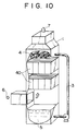
- Fig. 10 shows a CO 2 gas absorption device in which tubular structure fillers 40 are arranged instead of the tubular structure fillers 2 in Fig. 1.
- Other members in Fig. 10 have the same reference numerals as in Fig. 1, and they have already been described and so the description regarding them will be omitted.
- a mesh-like member such as a wire mesh may be interposed for the sake of the redispersion of the downward flowing absorbing liquid.
- the horizontal section of the filler has a shape selected from the group consisting of circles (A), circular arcs or continuously combined circular arcs (B) and straight lines (C) which neither mutually intersect nor contact.
- the horizontal section of the filler comprises only one of these shapes, but it may comprise two or more thereof.
- the shape of the horizontal section of the tubular structure filler 40 is one of the shapes usable in the present invention, and this shape comprises the group of the straight lines which neither mutually intersect nor contact, particularly it comprises parallel lines in this example.
- the tubular structure is constituted of a plurality of vertically arranged plates, as apparently shown in Fig. 10.
- the arrangement density of these plates should be selected so that the absorbing liquids flowing downward along the vertically or horizontally adjacent plates 13 may not come in contact with each other and so that the flow path resistance of the combustion exhaust gas may not be impaired.
- the plates are arranged at a higher density in consideration of these requirements. This arrangement density may be adjusted by interposing a spacer between the adjacent plates.
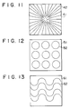
- Fig. 11 shows another example of the filler, i.e., a linear filler 42 in which the shape of a horizontal section comprises straight lines which neither mutually intersect nor contact;
- Fig. 12 shows a circular filler 52;
- Fig. 13 shows a continuous semicircular arc filler 62; and
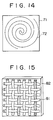
- Fig. 14 shows a spiral filler 72 which seems to be continuously combined circular arcs having a gradually increasing (or decreasing) radius.
- the continuous combination of the circular arcs additionally includes a smoothly formed free curve.
- a shape in which another circular arc is combined with the circular arc at a point is excluded from the category of the continuous combination regarding the present invention.
- each of reference numerals 41, 51, 61 and 71 in Figs. 11, 12, 13 and 14 is a CO 2 absorption device.
- the absorbing liquid fed from the top does not get together at a certain position to flow downward in the form of a string, but tends to expand in the horizontal direction of the inner wall, when it flows downward along the inner wall (the gas-liquid contact surface) of the tubular structure. In consequence, a gas-liquid contact efficiency is remarkably improved.
- Fig. 15 shows an enlarged view of the gas-liquid contact surface of the filler material.
- a weaving manner of the mesh 81 is plain weave, but this weave is not limited and any of various weaves inclusive of twill weave can be used. No particular restriction is put on a technique for sticking the mesh 81 on the plate 82, and any means such as welding or bonding can be utilized, as long as the mesh 14 stuck on the tubular structure having an optional shape in the horizontal section by such a technique does not separate from the plate during use.
- the mesh for example, a wire mesh, a plastic mesh and a mesh made of another material are usable.
- the mesh may be disposed so that the wires of the mesh may have a suitable angle to the ground.
- the size of the mesh to be selected is preferably 3 mesh or more, more preferably 8 mesh or more.
- the filler material of this example there can be employed a material which is not attacked by the gas and the liquid for the gas-liquid contact.
- a CO 2 absorbing test was made, as the simplest case, using a circular absorbing tube (Example), a triangular absorbing tube (Comparative Example 1), and a quadrangular absorbing tube (Comparative Example 2) which were the barrels of absorption devices having an inside diameter of 15 mm and which were made of a transparent acrylic resin.
- These tubes having the respective shapes were designed so that the total areas of their inside walls might be equal to each other.
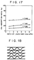
- Fig. 16 shows a testing equipment which is used herein.
- reference numeral 91 is a vertically disposed absorbing tube having a length of 1.15 m.
- Numeral 92 is a CO 2 absorbing liquid tank containing a 30% aqueous monoethanolamine solution, and the CO 2 absorbing liquid is fed to the top of the absorbing tube 91 through an absorbing liquid inlet 94 by means of a metering pump 93.
- the absorbing liquid is constantly fed to the inner wall of the absorbing tube at a flow rate of 4 liters/hour by overflow, as shown in this drawing.
- an expansion degree of the absorbing liquid, a wet degree of the inside walls and a CO 2 absorbing efficiency vary with the shapes of the above-mentioned absorbing tubes 91.
- the absorbing liquid which has flowed downward in contact with a test gas is led to a liquid reservoir 97.
- a CO 2 concentration of the test gas is analyzed in the vicinity of the gas inlet 95 of the absorbing tube 91 by a CO 2 continuous analyzer 98, and the test gas is then brought into contact with the CO 2 absorbing liquid during rising through the absorbing tube. After the CO 2 concentration of the test gas has been similarly analyzed again in front of a gas outlet 99, the test gas is discharged from the system. Every test was made at room temperature (25°C).
- Reference numerals 100, 100, 100 are three gas cylinders filled with a CO 2 gas, a nitrogen gas, and an oxygen gas, respectively.
- Numeral 101 is a gas flow rate controller, and 102 is a switch cock.
- Fig. 17 shows relations between a CO 2 absorption ratio (%, ordinate) and a liquid/gas ratio L/G (liter/m 3 N, abscissa) on the basis of the different shapes for the gas-liquid contact surfaces.
Landscapes
- Chemical & Material Sciences (AREA)
- Chemical Kinetics & Catalysis (AREA)
- Engineering & Computer Science (AREA)
- Analytical Chemistry (AREA)
- Oil, Petroleum & Natural Gas (AREA)
- General Chemical & Material Sciences (AREA)
- Organic Chemistry (AREA)
- Physics & Mathematics (AREA)
- Thermal Sciences (AREA)
- Mechanical Engineering (AREA)
- General Engineering & Computer Science (AREA)
- Gas Separation By Absorption (AREA)
- Treating Waste Gases (AREA)
- Physical Or Chemical Processes And Apparatus (AREA)
Priority Applications (1)
| Application Number | Priority Date | Filing Date | Title |
|---|---|---|---|
| EP97250219A EP0803277B1 (en) | 1993-01-13 | 1994-01-03 | Apparatus for gas-liquid contact |
Applications Claiming Priority (8)
| Application Number | Priority Date | Filing Date | Title |
|---|---|---|---|
| JP5004097A JPH06210121A (ja) | 1993-01-13 | 1993-01-13 | 気液接触装置 |
| JP4098/93 | 1993-01-13 | ||
| JP4097/93 | 1993-01-13 | ||
| JP05004098A JP3073350B2 (ja) | 1993-01-13 | 1993-01-13 | 気液接触装置 |
| JP59845/93 | 1993-03-19 | ||
| JP59844/93 | 1993-03-19 | ||
| JP5059845A JPH06269629A (ja) | 1993-03-19 | 1993-03-19 | 気液接触装置 |
| JP5059844A JPH06269628A (ja) | 1993-03-19 | 1993-03-19 | 気液接触装置 |
Related Child Applications (1)
| Application Number | Title | Priority Date | Filing Date |
|---|---|---|---|
| EP97250219A Division EP0803277B1 (en) | 1993-01-13 | 1994-01-03 | Apparatus for gas-liquid contact |
Publications (2)
| Publication Number | Publication Date |
|---|---|
| EP0606964A1 EP0606964A1 (en) | 1994-07-20 |
| EP0606964B1 true EP0606964B1 (en) | 1998-04-01 |
Family
ID=27454010
Family Applications (2)
| Application Number | Title | Priority Date | Filing Date |
|---|---|---|---|
| EP94250001A Expired - Lifetime EP0606964B1 (en) | 1993-01-13 | 1994-01-03 | Apparatus for gas-liquid contact |
| EP97250219A Expired - Lifetime EP0803277B1 (en) | 1993-01-13 | 1994-01-03 | Apparatus for gas-liquid contact |
Family Applications After (1)
| Application Number | Title | Priority Date | Filing Date |
|---|---|---|---|
| EP97250219A Expired - Lifetime EP0803277B1 (en) | 1993-01-13 | 1994-01-03 | Apparatus for gas-liquid contact |
Country Status (7)
| Country | Link |
|---|---|
| US (1) | US5536454A (da) |
| EP (2) | EP0606964B1 (da) |
| KR (1) | KR970003061B1 (da) |
| CN (1) | CN1048416C (da) |
| DE (2) | DE69430451T2 (da) |
| DK (1) | DK0803277T3 (da) |
| NO (1) | NO309026B1 (da) |
Families Citing this family (32)
| Publication number | Priority date | Publication date | Assignee | Title |
|---|---|---|---|---|
| JP3625901B2 (ja) * | 1995-06-30 | 2005-03-02 | 三菱電機株式会社 | サーボ制御システムの自動適正化方法および装置 |
| DE19530329A1 (de) * | 1995-08-17 | 1997-02-20 | Basf Ag | Packungsmaterial für Stoffaustausch-Kolonnen und Verfahren zu dessen Herstellung |
| DE19611976A1 (de) * | 1996-03-26 | 1997-10-02 | Basf Ag | Verfahren und Reaktor zur Durchführung von Stoffumwandlungen mit in Flüssigkeiten suspendierten Katalysatoren |
| RU2133140C1 (ru) * | 1998-03-05 | 1999-07-20 | Пензенская государственная архитектурно-строительная академия | Компактный тепломассообменный аппарат |
| SE512546C2 (sv) * | 1998-07-02 | 2000-04-03 | Flaekt Ab | Vätskefördelning i en kontaktapparat |
| DE69934262T2 (de) * | 1999-12-21 | 2007-05-24 | Alstom | Verteilung von gas und flüssigkeit in einer kontaktvorrichtung |
| US6517058B1 (en) | 2000-03-02 | 2003-02-11 | Sandkuhl Clay Works, Inc. | Fill packs for use in heat and mass transfer devices |
| CN1217911C (zh) | 2001-06-06 | 2005-09-07 | 株式会社日本触媒 | 防止易聚合物质发生聚合反应的方法和生产(甲基)丙烯酸或其酯的方法 |
| GB2402087B (en) * | 2002-03-01 | 2005-10-05 | Oiko Group Ltd | Device and method for removing pollutants from exhaust gases |
| US7011048B2 (en) * | 2004-07-22 | 2006-03-14 | Ener1, Inc. | Method and apparatus for liquid fuel preparation to improve combustion |
| US20060251547A1 (en) * | 2005-05-05 | 2006-11-09 | Windes Larry C | Family of stationary film generators and film support structures for vertical staged polymerization reactors |
| KR100682452B1 (ko) * | 2005-08-03 | 2007-02-15 | (주)에이엠티퍼시픽 | 듀얼 플로우 트레이의 용량 증대를 위한 기액 접촉장치 |
| KR100669032B1 (ko) * | 2006-08-21 | 2007-01-16 | 금호환경 주식회사 | 대기오염물질 제거용 유체 혼합 장치 |
| FR2913897B1 (fr) * | 2007-03-20 | 2009-11-20 | Inst Francais Du Petrole | Structure de garnissage pour colonne de mise en contact de fluides et methode de fabrication. |
| DE102007040892A1 (de) | 2007-08-24 | 2009-02-26 | Fsp Fluid Systems Partners Holding Ag | Gewelltes oder gefaltetes Flachmaterial |
| US8245863B2 (en) * | 2008-01-18 | 2012-08-21 | Dennis Pearlstein | Explosion resistant gas tank design |
| KR101166231B1 (ko) * | 2009-04-01 | 2012-07-17 | 양사헌 | 기액접촉 능력이 향상된 기액접촉판 |
| EP2489421B1 (en) | 2011-02-18 | 2021-03-31 | General Electric Technology GmbH | A wet scrubber for cleaning an effluent gas comprising an inlet gas distributor with a diffusor |
| JP5704238B2 (ja) | 2011-07-28 | 2015-04-22 | 株式会社Ihi | ガス分離装置及び充填材 |
| JP6180704B2 (ja) | 2011-12-12 | 2017-08-16 | 日本リファイン株式会社 | 気液接触装置 |
| FR2983737B1 (fr) * | 2011-12-13 | 2016-05-27 | Ifp Energies Now | Procede de desacidification d'un gaz avec mise en oeuvre d'un contacteur monolithe |
| JPWO2014017111A1 (ja) * | 2012-07-27 | 2016-07-07 | 株式会社Ihi | ガス分離装置及び充填材 |
| CA2944133C (en) | 2014-04-01 | 2019-04-30 | Ihi Corporation | Method of manufacturing packing and packing |
| DE102014215012A1 (de) * | 2014-07-30 | 2016-02-04 | Robert Bosch Gmbh | Gasreinigungseinheit für ein Batteriesystem |
| RU2568706C1 (ru) * | 2014-10-17 | 2015-11-20 | Игорь Анатольевич Мнушкин | Контактное устройство для проведения тепломассообмена и раздела фаз в секционированных перекрестноточных насадочных колоннах в системах газ-жидкость и жидкость-жидкость |
| JP6641844B2 (ja) | 2015-09-30 | 2020-02-05 | 株式会社Ihi | 充填材 |
| JP6812440B2 (ja) | 2016-08-01 | 2021-01-13 | 株式会社Ihi | 充填材及びその製造方法 |
| AU2019214659B2 (en) | 2018-01-30 | 2021-07-15 | Ihi Corporation | Packing, method for manufacturing same, and liquid film-forming structure |
| CN113474610B (zh) * | 2019-02-25 | 2023-09-15 | 乔治洛德方法研究和开发液化空气有限公司 | 集成至少一种热交换功能和一种蒸馏功能的基体 |
| CN112023868A (zh) * | 2020-09-08 | 2020-12-04 | 北京化工大学 | 一种新型高效无壁流规整丝网填料 |
| KR20240006597A (ko) * | 2021-05-11 | 2024-01-15 | 카본 엔지니어링 엘티디. | 이산화탄소 포집용 패킹을 갖는 기체-액체 접촉기 |
| WO2024003950A1 (en) * | 2022-06-30 | 2024-01-04 | Prote-In S.R.L. | Bioreactor and process for microbial gas fermentation |
Family Cites Families (28)
| Publication number | Priority date | Publication date | Assignee | Title |
|---|---|---|---|---|
| US1291833A (en) * | 1917-11-03 | 1919-01-21 | Ernest R Godward | Method of and apparatus for carburation. |
| US2253261A (en) * | 1939-08-09 | 1941-08-19 | Northern Blower Company | Dust collector |
| US2665123A (en) * | 1949-05-26 | 1954-01-05 | C D Patents Ltd | Apparatus for treating gases with liquids |
| US2783982A (en) * | 1955-01-27 | 1957-03-05 | Kahl Carl H William | Evaporative cooler with tower air flow |
| US2911056A (en) * | 1957-03-05 | 1959-11-03 | Walter L Edel | Absorber |
| US2917292A (en) * | 1957-03-29 | 1959-12-15 | Dow Chemical Co | Assemblies of extended surface elements for gas-liquid contact apparatus |
| US3155153A (en) * | 1959-07-10 | 1964-11-03 | Lizenzia A G | Rotatable body for transfer of moisture or/and heat |
| US3101382A (en) * | 1960-01-14 | 1963-08-20 | Carrier Corp | Gas and liquid contact apparatus |
| US3150211A (en) * | 1961-05-09 | 1964-09-22 | British Columbia Res Council | Gas-liquid contacting apparatus |
| US3353799A (en) * | 1963-05-22 | 1967-11-21 | American Radiator & Standard | Fluid treating apparatus and packing construction therefor |
| FR1377537A (fr) * | 1963-09-26 | 1964-11-06 | Tissmetal Lionel Dupont | élément de garnissage pour colonnes d'échange entre deux fluides |
| US3316064A (en) * | 1964-04-30 | 1967-04-25 | Hitachi Ltd | Apparatus for continuous polycondensation reaction |
| US3502445A (en) * | 1966-11-02 | 1970-03-24 | Union Oil Co | Apparatus for mixing fluids in concurrent downflow relationship |
| US3523762A (en) * | 1967-05-19 | 1970-08-11 | Universal Oil Prod Co | Baffled chamber for a plurality of contact beds to preclude diffused fluid flow |
| US3595626A (en) * | 1968-11-14 | 1971-07-27 | Du Pont | Ceramic fillers and covers for packed beds |
| CH520309A (de) * | 1970-08-20 | 1972-03-15 | Bbc Brown Boveri & Cie | Einrichtung für Verdunstungskühltürme mit Rieselwänden |
| US3723072A (en) * | 1971-03-12 | 1973-03-27 | Universal Oil Prod Co | Fluid contacting apparatus |
| CH537208A (de) * | 1971-04-29 | 1973-07-13 | Sulzer Ag | Mischeinrichtung für fliessfähige Medien |
| US4382046A (en) * | 1981-09-22 | 1983-05-03 | Ceramic Cooling Tower Company | Water cooling tower with layers of multi-cell tiles and spacers |
| DD232393A3 (de) * | 1984-08-01 | 1986-01-29 | Leipzig Chemieanlagen | Fluessigkeitsverteiler fuer gas-/dampf-fluessigkontaktapparate |
| CH664091A5 (de) * | 1985-01-30 | 1988-02-15 | Sulzer Ag | Packungskoerper aus duennem, folienartigen material fuer stoff- und waermeaustauschkolonnen zwischen fluessigen und gasfoermigen phasen. |
| EP0267961A4 (de) * | 1986-05-29 | 1990-01-26 | Uk Nii Prirodnykh Gazov | Massenaustauschgerät. |
| CA1270751A (en) * | 1986-12-01 | 1990-06-26 | Gilbert K. Chen | Structured tower packing |
| FI79177C (fi) * | 1988-02-05 | 1989-11-10 | Valmet Paper Machinery Inc | Boejningsreglerad vals. |
| LU87341A1 (fr) * | 1988-09-22 | 1990-04-06 | Wurth Paul Sa | Installation de chargement d'un four a cuve |
| JPH04271809A (ja) * | 1991-02-27 | 1992-09-28 | Mitsubishi Heavy Ind Ltd | 炭酸ガス吸収装置 |
| EP0501599A1 (en) * | 1991-02-27 | 1992-09-02 | Mitsubishi Jukogyo Kabushiki Kaisha | Apparatus for absorbing carbon dioxide gas |
| DE4111451A1 (de) * | 1991-04-09 | 1992-10-15 | Balcke Duerr Ag | Rieseleinbau-element fuer kuehltuerme |
-
1994
- 1994-01-03 DE DE69430451T patent/DE69430451T2/de not_active Expired - Fee Related
- 1994-01-03 DK DK97250219T patent/DK0803277T3/da active
- 1994-01-03 DE DE69409264T patent/DE69409264T2/de not_active Expired - Fee Related
- 1994-01-03 EP EP94250001A patent/EP0606964B1/en not_active Expired - Lifetime
- 1994-01-03 EP EP97250219A patent/EP0803277B1/en not_active Expired - Lifetime
- 1994-01-12 CN CN94100675A patent/CN1048416C/zh not_active Expired - Fee Related
- 1994-01-12 NO NO940110A patent/NO309026B1/no unknown
- 1994-01-12 KR KR1019940000375A patent/KR970003061B1/ko not_active Expired - Fee Related
-
1995
- 1995-06-05 US US08/462,054 patent/US5536454A/en not_active Expired - Lifetime
Also Published As
| Publication number | Publication date |
|---|---|
| DE69409264T2 (de) | 1998-09-03 |
| CN1097644A (zh) | 1995-01-25 |
| EP0803277A2 (en) | 1997-10-29 |
| NO940110L (no) | 1994-07-14 |
| CN1048416C (zh) | 2000-01-19 |
| US5536454A (en) | 1996-07-16 |
| DK0803277T3 (da) | 2002-06-17 |
| DE69430451T2 (de) | 2002-11-28 |
| DE69409264D1 (de) | 1998-05-07 |
| KR970003061B1 (ko) | 1997-03-14 |
| DE69430451D1 (de) | 2002-05-23 |
| KR940018127A (ko) | 1994-08-16 |
| NO940110D0 (no) | 1994-01-12 |
| NO309026B1 (no) | 2000-12-04 |
| EP0803277A3 (en) | 1997-12-29 |
| EP0606964A1 (en) | 1994-07-20 |
| EP0803277B1 (en) | 2002-04-17 |
Similar Documents
| Publication | Publication Date | Title |
|---|---|---|
| EP0606964B1 (en) | Apparatus for gas-liquid contact | |
| KR100447518B1 (ko) | 촉매증류구조물 | |
| US4882130A (en) | Porous structure of fluid contact | |
| CN104870074B (zh) | 用于混合气体和液体以重力、物理和化学收集化合物的方法和系统 | |
| USH1206H (en) | Cascade crossflow tower | |
| KR101948510B1 (ko) | 배기 가스를 처리하기 위한 장치 및 방법 | |
| CA2069293A1 (en) | Gas-liquid contact column with improved mist eliminator and method | |
| US4878925A (en) | Apparatus for removing foreign substances in gas | |
| RU2535700C2 (ru) | Способ и устройство для очистки текучих сред | |
| JPH06210121A (ja) | 気液接触装置 | |
| US4775499A (en) | Gas-liquid contacting apparatus | |
| JPH06269629A (ja) | 気液接触装置 | |
| JPH06269628A (ja) | 気液接触装置 | |
| KR950014023B1 (ko) | 기액접촉장치 | |
| US4118206A (en) | Oil mist filtering apparatus and method | |
| JPH02245202A (ja) | 気―液接触トレー | |
| CN217340506U (zh) | 一种亚微米级细微颗粒物分离元件和装置 | |
| WO2024205622A1 (en) | Air-liquid contactor for carbon dioxide direct air capture using aqueous solvent | |
| JPH08150314A (ja) | 気液接触装置 | |
| JP2003113487A (ja) | ガス発生システムおよび気液分離装置 | |
| CN212215529U (zh) | 复合结构环形填料及喷淋塔 | |
| CN2236483Y (zh) | 填料式浮选柱 | |
| JPH07232058A (ja) | ランダムカラムパッキング | |
| KR102530133B1 (ko) | 촉매 증류를 위한 구조화된 패킹 | |
| JPH06210122A (ja) | 気液接触装置 |
Legal Events
| Date | Code | Title | Description |
|---|---|---|---|
| PUAI | Public reference made under article 153(3) epc to a published international application that has entered the european phase |
Free format text: ORIGINAL CODE: 0009012 |
|
| AK | Designated contracting states |
Kind code of ref document: A1 Designated state(s): DE DK GB IT NL |
|
| RIN1 | Information on inventor provided before grant (corrected) |
Inventor name: HOTTA, YOSHITSUGU, C/O THE KANSAI ELECTRIC POWER Inventor name: FUJII, MASUMI, C/O THE KANSAI ELECTRIC POWER Inventor name: YOSHIDA, KUNIHIKO, C/O THE KANSAI ELECTRIC POWER Inventor name: KAWASAKI, MASAMI, C/O THE KANSAI ELECTRIC POWER Inventor name: SHIMOJO, SHIGERU, C/O TECHNICAL RESEARCH CENTER Inventor name: MITSUOKA, SHIGEAKI, C/O HIROSHIMA RES & DEV CENTE Inventor name: IIJIMA, MASAKI, C/O MITSUBISHI JUKOGYO K.K. Inventor name: KARASAKI, MUTSUNORI, C/O MITSUBISHI JUKOGYO K.K. |
|
| 17P | Request for examination filed |
Effective date: 19940720 |
|
| 17Q | First examination report despatched |
Effective date: 19951019 |
|
| GRAG | Despatch of communication of intention to grant |
Free format text: ORIGINAL CODE: EPIDOS AGRA |
|
| GRAG | Despatch of communication of intention to grant |
Free format text: ORIGINAL CODE: EPIDOS AGRA |
|
| GRAH | Despatch of communication of intention to grant a patent |
Free format text: ORIGINAL CODE: EPIDOS IGRA |
|
| GRAH | Despatch of communication of intention to grant a patent |
Free format text: ORIGINAL CODE: EPIDOS IGRA |
|
| GRAA | (expected) grant |
Free format text: ORIGINAL CODE: 0009210 |
|
| AK | Designated contracting states |
Kind code of ref document: B1 Designated state(s): DE DK GB IT NL |
|
| XX | Miscellaneous (additional remarks) |
Free format text: TEILANMELDUNG 97250219.9 EINGEREICHT AM 24/07/97. |
|
| REF | Corresponds to: |
Ref document number: 69409264 Country of ref document: DE Date of ref document: 19980507 |
|
| ITF | It: translation for a ep patent filed | ||
| PG25 | Lapsed in a contracting state [announced via postgrant information from national office to epo] |
Ref country code: DK Free format text: LAPSE BECAUSE OF FAILURE TO SUBMIT A TRANSLATION OF THE DESCRIPTION OR TO PAY THE FEE WITHIN THE PRESCRIBED TIME-LIMIT Effective date: 19980701 |
|
| PLBE | No opposition filed within time limit |
Free format text: ORIGINAL CODE: 0009261 |
|
| STAA | Information on the status of an ep patent application or granted ep patent |
Free format text: STATUS: NO OPPOSITION FILED WITHIN TIME LIMIT |
|
| 26N | No opposition filed | ||
| REG | Reference to a national code |
Ref country code: GB Ref legal event code: IF02 |
|
| PGFP | Annual fee paid to national office [announced via postgrant information from national office to epo] |
Ref country code: DE Payment date: 20061229 Year of fee payment: 14 |
|
| PGFP | Annual fee paid to national office [announced via postgrant information from national office to epo] |
Ref country code: NL Payment date: 20070115 Year of fee payment: 14 |
|
| PGFP | Annual fee paid to national office [announced via postgrant information from national office to epo] |
Ref country code: IT Payment date: 20070601 Year of fee payment: 14 |
|
| GBPC | Gb: european patent ceased through non-payment of renewal fee |
Effective date: 20080103 |
|
| NLV4 | Nl: lapsed or anulled due to non-payment of the annual fee |
Effective date: 20080801 |
|
| PG25 | Lapsed in a contracting state [announced via postgrant information from national office to epo] |
Ref country code: NL Free format text: LAPSE BECAUSE OF NON-PAYMENT OF DUE FEES Effective date: 20080801 Ref country code: DE Free format text: LAPSE BECAUSE OF NON-PAYMENT OF DUE FEES Effective date: 20080801 |
|
| PG25 | Lapsed in a contracting state [announced via postgrant information from national office to epo] |
Ref country code: GB Free format text: LAPSE BECAUSE OF NON-PAYMENT OF DUE FEES Effective date: 20080103 |
|
| PG25 | Lapsed in a contracting state [announced via postgrant information from national office to epo] |
Ref country code: IT Free format text: LAPSE BECAUSE OF NON-PAYMENT OF DUE FEES Effective date: 20080103 |
|
| REG | Reference to a national code |
Ref country code: GB Ref legal event code: S28 Free format text: RESTORATION ALLOWED Effective date: 20100209 |
|
| PGFP | Annual fee paid to national office [announced via postgrant information from national office to epo] |
Ref country code: GB Payment date: 20130102 Year of fee payment: 20 |
|
| REG | Reference to a national code |
Ref country code: GB Ref legal event code: PE20 Expiry date: 20140102 |
|
| PG25 | Lapsed in a contracting state [announced via postgrant information from national office to epo] |
Ref country code: GB Free format text: LAPSE BECAUSE OF EXPIRATION OF PROTECTION Effective date: 20140102 |