EP0803277A2 - Apparatus for gas-liquid contact - Google Patents
Apparatus for gas-liquid contact Download PDFInfo
- Publication number
- EP0803277A2 EP0803277A2 EP97250219A EP97250219A EP0803277A2 EP 0803277 A2 EP0803277 A2 EP 0803277A2 EP 97250219 A EP97250219 A EP 97250219A EP 97250219 A EP97250219 A EP 97250219A EP 0803277 A2 EP0803277 A2 EP 0803277A2
- Authority
- EP
- European Patent Office
- Prior art keywords
- gas
- liquid
- fillers
- absorbing
- liquid contact
- Prior art date
- Legal status (The legal status is an assumption and is not a legal conclusion. Google has not performed a legal analysis and makes no representation as to the accuracy of the status listed.)
- Granted
Links
- 239000007788 liquid Substances 0.000 title claims abstract description 203
- 239000000945 filler Substances 0.000 claims abstract description 95
- 238000002485 combustion reaction Methods 0.000 claims description 18
- 239000007789 gas Substances 0.000 description 94
- 238000010521 absorption reaction Methods 0.000 description 27
- 238000012360 testing method Methods 0.000 description 26
- 239000000463 material Substances 0.000 description 11
- VEXZGXHMUGYJMC-UHFFFAOYSA-N Hydrochloric acid Chemical compound Cl VEXZGXHMUGYJMC-UHFFFAOYSA-N 0.000 description 10
- 230000000694 effects Effects 0.000 description 9
- 239000000126 substance Substances 0.000 description 9
- 229910001220 stainless steel Inorganic materials 0.000 description 8
- 239000010935 stainless steel Substances 0.000 description 8
- VYPSYNLAJGMNEJ-UHFFFAOYSA-N Silicium dioxide Chemical compound O=[Si]=O VYPSYNLAJGMNEJ-UHFFFAOYSA-N 0.000 description 7
- 238000000034 method Methods 0.000 description 7
- IJGRMHOSHXDMSA-UHFFFAOYSA-N Atomic nitrogen Chemical compound N#N IJGRMHOSHXDMSA-UHFFFAOYSA-N 0.000 description 6
- 230000000052 comparative effect Effects 0.000 description 6
- 230000007423 decrease Effects 0.000 description 6
- 238000004519 manufacturing process Methods 0.000 description 5
- 239000004576 sand Substances 0.000 description 5
- HZAXFHJVJLSVMW-UHFFFAOYSA-N 2-Aminoethan-1-ol Chemical compound NCCO HZAXFHJVJLSVMW-UHFFFAOYSA-N 0.000 description 4
- 230000001771 impaired effect Effects 0.000 description 4
- 239000004033 plastic Substances 0.000 description 4
- 229920003023 plastic Polymers 0.000 description 4
- 229910021578 Iron(III) chloride Inorganic materials 0.000 description 3
- 238000007664 blowing Methods 0.000 description 3
- 230000008602 contraction Effects 0.000 description 3
- 238000010586 diagram Methods 0.000 description 3
- RBTARNINKXHZNM-UHFFFAOYSA-K iron trichloride Chemical compound Cl[Fe](Cl)Cl RBTARNINKXHZNM-UHFFFAOYSA-K 0.000 description 3
- 230000002035 prolonged effect Effects 0.000 description 3
- MYMOFIZGZYHOMD-UHFFFAOYSA-N Dioxygen Chemical compound O=O MYMOFIZGZYHOMD-UHFFFAOYSA-N 0.000 description 2
- 230000003247 decreasing effect Effects 0.000 description 2
- 229910001873 dinitrogen Inorganic materials 0.000 description 2
- 229910001882 dioxygen Inorganic materials 0.000 description 2
- 238000011156 evaluation Methods 0.000 description 2
- 239000000835 fiber Substances 0.000 description 2
- 239000002803 fossil fuel Substances 0.000 description 2
- 239000002184 metal Substances 0.000 description 2
- 238000000465 moulding Methods 0.000 description 2
- 229910052757 nitrogen Inorganic materials 0.000 description 2
- 230000000630 rising effect Effects 0.000 description 2
- 238000005488 sandblasting Methods 0.000 description 2
- 238000004381 surface treatment Methods 0.000 description 2
- 239000004925 Acrylic resin Substances 0.000 description 1
- 229920000178 Acrylic resin Polymers 0.000 description 1
- 239000004698 Polyethylene Substances 0.000 description 1
- 229910001566 austenite Inorganic materials 0.000 description 1
- 239000000919 ceramic Substances 0.000 description 1
- 239000011248 coating agent Substances 0.000 description 1
- 238000000576 coating method Methods 0.000 description 1
- 238000005260 corrosion Methods 0.000 description 1
- 230000007797 corrosion Effects 0.000 description 1
- 238000009792 diffusion process Methods 0.000 description 1
- 238000007598 dipping method Methods 0.000 description 1
- 238000007599 discharging Methods 0.000 description 1
- 238000001125 extrusion Methods 0.000 description 1
- 230000020169 heat generation Effects 0.000 description 1
- 230000014759 maintenance of location Effects 0.000 description 1
- 238000005259 measurement Methods 0.000 description 1
- 239000002245 particle Substances 0.000 description 1
- -1 polyethylene Polymers 0.000 description 1
- 229920000573 polyethylene Polymers 0.000 description 1
- 229910052573 porcelain Inorganic materials 0.000 description 1
- 238000010248 power generation Methods 0.000 description 1
- 238000012545 processing Methods 0.000 description 1
- 239000010703 silicon Substances 0.000 description 1
- 229910052710 silicon Inorganic materials 0.000 description 1
- 239000000377 silicon dioxide Substances 0.000 description 1
- 125000006850 spacer group Chemical group 0.000 description 1
- 238000010792 warming Methods 0.000 description 1
- XLYOFNOQVPJJNP-UHFFFAOYSA-N water Substances O XLYOFNOQVPJJNP-UHFFFAOYSA-N 0.000 description 1
- 238000009941 weaving Methods 0.000 description 1
Images


Classifications
-
- B—PERFORMING OPERATIONS; TRANSPORTING
- B01—PHYSICAL OR CHEMICAL PROCESSES OR APPARATUS IN GENERAL
- B01D—SEPARATION
- B01D53/00—Separation of gases or vapours; Recovering vapours of volatile solvents from gases; Chemical or biological purification of waste gases, e.g. engine exhaust gases, smoke, fumes, flue gases, aerosols
- B01D53/14—Separation of gases or vapours; Recovering vapours of volatile solvents from gases; Chemical or biological purification of waste gases, e.g. engine exhaust gases, smoke, fumes, flue gases, aerosols by absorption
- B01D53/18—Absorbing units; Liquid distributors therefor
- B01D53/185—Liquid distributors
-
- B—PERFORMING OPERATIONS; TRANSPORTING
- B01—PHYSICAL OR CHEMICAL PROCESSES OR APPARATUS IN GENERAL
- B01D—SEPARATION
- B01D53/00—Separation of gases or vapours; Recovering vapours of volatile solvents from gases; Chemical or biological purification of waste gases, e.g. engine exhaust gases, smoke, fumes, flue gases, aerosols
- B01D53/14—Separation of gases or vapours; Recovering vapours of volatile solvents from gases; Chemical or biological purification of waste gases, e.g. engine exhaust gases, smoke, fumes, flue gases, aerosols by absorption
- B01D53/1456—Removing acid components
- B01D53/1475—Removing carbon dioxide
-
- B—PERFORMING OPERATIONS; TRANSPORTING
- B01—PHYSICAL OR CHEMICAL PROCESSES OR APPARATUS IN GENERAL
- B01D—SEPARATION
- B01D53/00—Separation of gases or vapours; Recovering vapours of volatile solvents from gases; Chemical or biological purification of waste gases, e.g. engine exhaust gases, smoke, fumes, flue gases, aerosols
- B01D53/14—Separation of gases or vapours; Recovering vapours of volatile solvents from gases; Chemical or biological purification of waste gases, e.g. engine exhaust gases, smoke, fumes, flue gases, aerosols by absorption
- B01D53/18—Absorbing units; Liquid distributors therefor
-
- B—PERFORMING OPERATIONS; TRANSPORTING
- B01—PHYSICAL OR CHEMICAL PROCESSES OR APPARATUS IN GENERAL
- B01J—CHEMICAL OR PHYSICAL PROCESSES, e.g. CATALYSIS OR COLLOID CHEMISTRY; THEIR RELEVANT APPARATUS
- B01J19/00—Chemical, physical or physico-chemical processes in general; Their relevant apparatus
- B01J19/32—Packing elements in the form of grids or built-up elements for forming a unit or module inside the apparatus for mass or heat transfer
-
- F—MECHANICAL ENGINEERING; LIGHTING; HEATING; WEAPONS; BLASTING
- F23—COMBUSTION APPARATUS; COMBUSTION PROCESSES
- F23J—REMOVAL OR TREATMENT OF COMBUSTION PRODUCTS OR COMBUSTION RESIDUES; FLUES
- F23J15/00—Arrangements of devices for treating smoke or fumes
- F23J15/02—Arrangements of devices for treating smoke or fumes of purifiers, e.g. for removing noxious material
-
- B—PERFORMING OPERATIONS; TRANSPORTING
- B01—PHYSICAL OR CHEMICAL PROCESSES OR APPARATUS IN GENERAL
- B01J—CHEMICAL OR PHYSICAL PROCESSES, e.g. CATALYSIS OR COLLOID CHEMISTRY; THEIR RELEVANT APPARATUS
- B01J2219/00—Chemical, physical or physico-chemical processes in general; Their relevant apparatus
- B01J2219/32—Details relating to packing elements in the form of grids or built-up elements for forming a unit of module inside the apparatus for mass or heat transfer
- B01J2219/322—Basic shape of the elements
- B01J2219/32203—Sheets
- B01J2219/32206—Flat sheets
-
- B—PERFORMING OPERATIONS; TRANSPORTING
- B01—PHYSICAL OR CHEMICAL PROCESSES OR APPARATUS IN GENERAL
- B01J—CHEMICAL OR PHYSICAL PROCESSES, e.g. CATALYSIS OR COLLOID CHEMISTRY; THEIR RELEVANT APPARATUS
- B01J2219/00—Chemical, physical or physico-chemical processes in general; Their relevant apparatus
- B01J2219/32—Details relating to packing elements in the form of grids or built-up elements for forming a unit of module inside the apparatus for mass or heat transfer
- B01J2219/322—Basic shape of the elements
- B01J2219/32203—Sheets
- B01J2219/3221—Corrugated sheets
-
- B—PERFORMING OPERATIONS; TRANSPORTING
- B01—PHYSICAL OR CHEMICAL PROCESSES OR APPARATUS IN GENERAL
- B01J—CHEMICAL OR PHYSICAL PROCESSES, e.g. CATALYSIS OR COLLOID CHEMISTRY; THEIR RELEVANT APPARATUS
- B01J2219/00—Chemical, physical or physico-chemical processes in general; Their relevant apparatus
- B01J2219/32—Details relating to packing elements in the form of grids or built-up elements for forming a unit of module inside the apparatus for mass or heat transfer
- B01J2219/322—Basic shape of the elements
- B01J2219/32203—Sheets
- B01J2219/32213—Plurality of essentially parallel sheets
-
- B—PERFORMING OPERATIONS; TRANSPORTING
- B01—PHYSICAL OR CHEMICAL PROCESSES OR APPARATUS IN GENERAL
- B01J—CHEMICAL OR PHYSICAL PROCESSES, e.g. CATALYSIS OR COLLOID CHEMISTRY; THEIR RELEVANT APPARATUS
- B01J2219/00—Chemical, physical or physico-chemical processes in general; Their relevant apparatus
- B01J2219/32—Details relating to packing elements in the form of grids or built-up elements for forming a unit of module inside the apparatus for mass or heat transfer
- B01J2219/322—Basic shape of the elements
- B01J2219/32203—Sheets
- B01J2219/32224—Sheets characterised by the orientation of the sheet
- B01J2219/32227—Vertical orientation
-
- B—PERFORMING OPERATIONS; TRANSPORTING
- B01—PHYSICAL OR CHEMICAL PROCESSES OR APPARATUS IN GENERAL
- B01J—CHEMICAL OR PHYSICAL PROCESSES, e.g. CATALYSIS OR COLLOID CHEMISTRY; THEIR RELEVANT APPARATUS
- B01J2219/00—Chemical, physical or physico-chemical processes in general; Their relevant apparatus
- B01J2219/32—Details relating to packing elements in the form of grids or built-up elements for forming a unit of module inside the apparatus for mass or heat transfer
- B01J2219/322—Basic shape of the elements
- B01J2219/32203—Sheets
- B01J2219/32237—Sheets comprising apertures or perforations
-
- B—PERFORMING OPERATIONS; TRANSPORTING
- B01—PHYSICAL OR CHEMICAL PROCESSES OR APPARATUS IN GENERAL
- B01J—CHEMICAL OR PHYSICAL PROCESSES, e.g. CATALYSIS OR COLLOID CHEMISTRY; THEIR RELEVANT APPARATUS
- B01J2219/00—Chemical, physical or physico-chemical processes in general; Their relevant apparatus
- B01J2219/32—Details relating to packing elements in the form of grids or built-up elements for forming a unit of module inside the apparatus for mass or heat transfer
- B01J2219/322—Basic shape of the elements
- B01J2219/32286—Grids or lattices
-
- B—PERFORMING OPERATIONS; TRANSPORTING
- B01—PHYSICAL OR CHEMICAL PROCESSES OR APPARATUS IN GENERAL
- B01J—CHEMICAL OR PHYSICAL PROCESSES, e.g. CATALYSIS OR COLLOID CHEMISTRY; THEIR RELEVANT APPARATUS
- B01J2219/00—Chemical, physical or physico-chemical processes in general; Their relevant apparatus
- B01J2219/32—Details relating to packing elements in the form of grids or built-up elements for forming a unit of module inside the apparatus for mass or heat transfer
- B01J2219/322—Basic shape of the elements
- B01J2219/32296—Honeycombs
-
- B—PERFORMING OPERATIONS; TRANSPORTING
- B01—PHYSICAL OR CHEMICAL PROCESSES OR APPARATUS IN GENERAL
- B01J—CHEMICAL OR PHYSICAL PROCESSES, e.g. CATALYSIS OR COLLOID CHEMISTRY; THEIR RELEVANT APPARATUS
- B01J2219/00—Chemical, physical or physico-chemical processes in general; Their relevant apparatus
- B01J2219/32—Details relating to packing elements in the form of grids or built-up elements for forming a unit of module inside the apparatus for mass or heat transfer
- B01J2219/324—Composition or microstructure of the elements
- B01J2219/32408—Metal
-
- Y—GENERAL TAGGING OF NEW TECHNOLOGICAL DEVELOPMENTS; GENERAL TAGGING OF CROSS-SECTIONAL TECHNOLOGIES SPANNING OVER SEVERAL SECTIONS OF THE IPC; TECHNICAL SUBJECTS COVERED BY FORMER USPC CROSS-REFERENCE ART COLLECTIONS [XRACs] AND DIGESTS
- Y02—TECHNOLOGIES OR APPLICATIONS FOR MITIGATION OR ADAPTATION AGAINST CLIMATE CHANGE
- Y02E—REDUCTION OF GREENHOUSE GAS [GHG] EMISSIONS, RELATED TO ENERGY GENERATION, TRANSMISSION OR DISTRIBUTION
- Y02E20/00—Combustion technologies with mitigation potential
- Y02E20/32—Direct CO2 mitigation
-
- Y—GENERAL TAGGING OF NEW TECHNOLOGICAL DEVELOPMENTS; GENERAL TAGGING OF CROSS-SECTIONAL TECHNOLOGIES SPANNING OVER SEVERAL SECTIONS OF THE IPC; TECHNICAL SUBJECTS COVERED BY FORMER USPC CROSS-REFERENCE ART COLLECTIONS [XRACs] AND DIGESTS
- Y10—TECHNICAL SUBJECTS COVERED BY FORMER USPC
- Y10S—TECHNICAL SUBJECTS COVERED BY FORMER USPC CROSS-REFERENCE ART COLLECTIONS [XRACs] AND DIGESTS
- Y10S261/00—Gas and liquid contact apparatus
- Y10S261/72—Packing elements
Definitions
- the present invention relates to an apparatus for gas-liquid contact, particularly to an apparatus for gas-liquid contact capable of efficiently bringing a gas into contact with a liquid like a CO 2 gas absorption device for removing a CO 2 gas from an exhaust gas by bringing the CO 2 gas contained in the exhaust gas into contact with a CO 2 gas absorbing liquid.
- Such an apparatus is for example disclosed in EP-A-0501599.
- a greenhouse effect due to CO 2 has been pointed out as one of the causes of a global atmosphere warming phenomenon, and it has been internationally required to urgently take measures for the greenhouse effect in order to protect a global atmospheric environment.
- the generation source of CO 2 lies in every human activity field in which a fossil fuel is burnt, and the exhaust control of CO 2 tends to be furher strengened in future.
- As one of the measures for the exhaust control for power generation facilities of thermal power plants in which a large amount of the fossil fuel is used, there have been energetically researched a method for removing and collecting CO 2 from the combustion exhaust gas of a boiler, and a method for storing C0 2 without discharging it to the atmosphere.
- a gas-liquid contact technique which is employed in an absorption process of a chemical plant, a bubble cap plate tower and a packed tower have been used so that the gas-liquid contact may be achieved as much as possible.
- Raschig rings having various shapes have been used.
- an apparatus for gas-liquid contact In the apparatus for the gas-liquid contact for absorbing CO 2 in the combustion exhaust gas, it is necessary to efficiently treat a large amount of the gas in a short time. Therefore, an apparatus for gas-liquid contact is desired in which expansion, contraction and collision of a gas flow are not in a gas passage, no eddy occurs, and unnecessary pressure loss due to the above factors hardly takes place. Moreover, an apparatus for gas-liquid contact is desired which is constituted as simply as possible and by which a gas-liquid contact area and a contact time can be increased to resultingly heighten a contact efficiency.
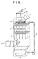
- the present inventors have previously suggested a CO 2 gas absortion device in which many fillers are arranged so that the gas-liquid contact surfaces of the fillers may be parallel with a gas flow and they comprise tubular structures whose cross section has any of various shapes and whose tubular portions are straight, as shown in Fig. 1 (which shows the whole constitutional view of the CO 2 gas absorption device which will also be used in an embodiment of the apparatus for gas-liquid contact of the present invention) (cf. EP-A-0 501 599). That is, in Fig.
- reference numeral 1 is a CO 2 gas absorption device
- numerals 2, 2 are fillers comprising tubular structures whose tubular portion is straight, and these fillers are arranged in the form of plural steps in a substantially vertical direction.
- Reference numeral 3 is a line for transporting a CO 2 absorbing liquid
- numeral 4 is a liquid dispersing nozzle
- 5 is a storage space of the absorbing liquid in which CO 2 is absorbed
- 6 is a combustion exhaust gas containing CO 2
- 7 is a clean exhaust gas from which CO 2 is removed.
- any of the various shapes can be employed as the cross section of the fillers 2 comprising the tubular structures, and this cross section may be constituted of one or a combination of these shapes.
- the flow of the gas is parallel with the absorbing surface (the gas-liquid contact surface).
- the absorbing liquid is held by the absorbing surfaces of the fillers 2 comprising the tubular structures, and the held absorbing liquid is brought into contact with the gas flow to absorb C0 2 while flowing downward along the surfaces. Therefore, according to this constitution the pressure loss can be remarkably decreased, in contrast to fillers such as conventional Raschig rings.
- the above-mentioned CO 2 gas absorption device has the following problems.
- One object of the present invention is to provide an apparatus for gas-liquid contact capable of solving the ,above-mentioned problem (a) and improving a gas-liquid contact efficiency by increasing the contact area per unit area of the gas-liquid contact surfaces of tubular structure fillers.
- a further object of the present invention is to provide an apparatus for gas-liquid contact capable of solving the above-mentioned problem (b) and improving dispersibility during the downward flow of an absorbing liquid from upper step to lower step of the tubular structure fillers.
- a still further object of the present invention is to provide an apparatus for gas-liquid contact capable of solving the above-mentioned problem (c) by the use of a specific material for the gas-liquid contact surfaces of the tubular structure fillers.
- Another object of the present invention is to provide an apparatus for gas-liquid contact capable of solving the above-mentioned problem (d) by forming the horizontal section of the tubular structure fillers into a specific shape.
- the constitutions of the present invention for achieving the above-mentioned objects are characterized by the following items (1) to (10) in an apparatus for gas-liquid contact comprising tubular structure fillers having straight tubular portions arranged (in the apparatus) in a substantially vertical direction in plural steps so that the gas-licuid contact surfaces of the fillers may be parallel with the flow of the gas, whereby the gas can be brought into contact with the liquid by feeding the liquid from a site above the fillers, allowing the liquid to flow downward along the filler surfaces, and feeding the gas from a site under the fillers.
- the gas-liquid contact area on the inner walls of the fillers arranged in the apparatus for gas-liquid contact can be increased, and the residence time of the downward flowing liquid can be prolonged, whereby the gas-liquid contact efficiency can be remarkably improved.
- the liquid does not flow downward along the gas-liquid contact surface in the form of a string, but it widely expands on the contact surface, so that the residence time of the downward flowing liquid is prolonged and consequently the gas-liquid contact efficiency can be noticeably improved.
- tubular structure fillers 2 are vertically arranged in the form of plural steps in a CO 2 absorption device body 1, and these fillers have an optional shape in a horizontal section and have straight tubular portions.
- the horizontal section of the tubular structure fillers 2 shows the shape of lattice.
- the apparatus body 1 is equipped with a CO 2 absorbing liquid transport line 3 for connecting a liquid dispersing nozzle 4 in the top of the body 1 to an absorbing liquid storage space 5 on the,bottom of the body 1.
- An absorbing liquid reproduction process (not shown) for removing CO 2 from the absorbing liquid to improve the absorbing capacity may be provided in the middle of the transport line 3.
- the liquid dispersing nozzle 4 is installed so as to disperse the CO 2 absorbing liquid delivered through the transport line 3 to the fillers 2 as uniformly as possible.
- At the top of the apparatus body 1 there is formed an opening through which a clean exhaust gas 7 is discharged to the outside, and this clean exhaust gas 7 is obtained by removing CO 2 from the combustion exhaust gas with the CO 2 absorbing liquid while the gas flows upward through the fillers 2.
- the filler 2 shows an enlarged partial view of the tubular structure filler 2.
- the filler 2 is formed into a tubular structure having a lattice-like horizontal section, and through this tubular structure filler 2, the exhaust gas 6 lcan flow upward from the bottom of the apparatus body 1 and the fed CO 2 absorbing liquid can also flow downward from the liquid dispersing nozzle 4.
- the inside walls of the tubular portions constitute absorbing surfaces (gas-liquid contact surfaces) on which the combustion exhaust gas 6 is reacted with the CO 2 absorbing liquid.
- the filler 2 is constituted of porcelaneous tubular structures 21 having one lattice side length De of, for example, 15 mm which are laterally arranged as shown by reference numerals 2 1 , 2 2 , 2 3 , 2 4 ... in Fig. 1.
- the thus constituted filler 2 has, for example, an area of 300 mm 2 and a length of 500 mm.
- the fillers 2 are vertically arranged in the form of, for example, 20 stages in the apparatus body 1. According to the fillers 2 comprising the abovementioned tubular structures, the gas flows in parallel with the absorbing surfaces, and expansion, contraction and collision of the gas flow and an eddy scarcely occur in a gas path, so that pressure loss due to these factors can be sufficiently inhibited.
- the shape of the tubular structure 2' is not restricted to the lattice in Fig. 2, and for example, hexagon, rectangle, triangle and U shape are usable, as long as they form the gas parallel flow.
- a material for the tubular structure 2' a porcelain, a metal, a ceramic fiber such as silica fiber and a plastic such as polyethylene are usable, so long as they are not corroded or swelled by the CO 2 absorbing liquid.
- the structure shown in Fig. 2 can usually be manufactured by an extrusion molding method, but a combination of a flat plate and a molding plate or a corrugate machine molding method is also applicable.
- an economical manufacturing method can be selected in accordance with the shape and material.
- a feature of the present invention is that the absorbing surfaces, i.e.,the gas-liquid contact surfaces of the tubular structures 2' are treated in a rough state so as to have a center line average height of 50 ⁇ m or more.
- the rough-surface treatment is carried out by sandblasting, depending upon a material of the tubular structures. That is, the roughness of the absorbing surface is increased by blowing sand on the absorbing surfaces. This roughness can be adjusted by changing a grain diameter of the sand and a blowing time.
- the sand it is also possible to use particles of a plastic, silicon or a metal, depending upon the material of the absorbing surfaces.
- the above-mentioned center line average height is preferably in the range of from 50 to 100 um.
- the rough surface treatment may be achieved by a chemical treatment, depending upon the material of the absorbing surfaces.
- stainless steel as the material of the tubular structures 2', FeCl 3 , HCl or HCl + H 2 0 2 can be used as chemicals for the chemical treatment.
- the absorbing surfaces are corroded with these chemicals to become properly rough. A degree of the corrosion is determined by a chemical concentration x a dipping time x a temperature.
- Table 1 shows chemical treatment conditions, treatment results and evaluations.
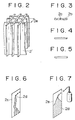
- Table 1 Chemicals Conc., Temp. and Time Surface Evaluation FeCl 3 30% - 40-60°C - 2-10 min See Fig. 3 ⁇ HCl 30% - 40-60°C - 5-10 min See Fig. 4 ⁇ HCl + H 2 O 2 35+1% - 100°C* - 1 min or less See Fig. 5 ⁇ * The temperature was raised to 100°C by heat generation.
- JIS indication: SUS304; austenite JIS indication: SUS304; austenite
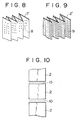
- the tubular structure 2' is constituted of a porous plate 8 provided with a large number of small holes, as shown in Fig. 8.
- a rate of the hole,area of the porous plate 8 is preferably 20% or less.
- the tubular structure 2' may be formed in the shape of a lattice in its horizontal section as described above, or it may be formed in the shape of hexagon, rectangle, triangle or U shape.
- the tubular structure 2' is constituted of a mesh 9 comprising a wire mesh, as shown in Fig. 9.
- the absorbing liquid can reside in the mesh of the mesh for a long time owing to surface tension or cohesive force, and the diffusion of the absorbing liquid can be easily achieved on the absorbing surface.
- this embodiment also makes it possible to increase the gas-liquid contact area and to improve the CO 2 absorbing efficiency. Even if the mesh of a plastic or another material is used instead of the wire mesh, a similar effect can be obtained. No particular restriction is put on a weaving manner of the mesh, and plain weave, twill weave or the like can be employed.
- the mesh may be disposed so that the wires of the mesh may have a suitable angle to the ground.
- the size of the mesh to be selected is preferably 3 mesh or more, more preferably 8 mesh or more
- a CO 2 gas absorption device for removing CO 2 from a combustion exhaust gas by bringing the combustion exhaust gas containing CO 2 into contact with a CO 2 absorbing liquid
- the description of Figs. 1 and 2 has been made in the above-mentioned first embodiment, and so it will be omitted.
- the present invention is characterized in that a dispersing plate 10 is interposed between tubular structure fillers 2 vertically arranged in the form of many steps, as shown in the cross section of Fig. 10.
- the dispersing plate 10 is constituted of, for example, a porous plate.
- a rate of the hole area of the porous plate (a rate of the hole area to the entire area inclusive of the hole area) is preferably 80% or more in order to prevent the increase of pressure loss at the time of the passage of the gas.
- the shape of the holes of the porous plate is not limited to a circle, and a deformed shape such as a star is also acceptable.
- Fig. 11 shows the flow of the absorbing liquid in the case that any dispersing plate is not interposed between the vertically arranged tubular structure fillers 2, 2. In this case, the absorbing liquid flows downward from the lowermost surface of the filler 2 in the form of strings, so that the dispersibility of the liquid is impaired.
- Fig. 12 shows a case where the dispersing plate 10 is interposed between the fillers 2, 2.
- the absorbing liquid flowing downward from the lowermost surface of the upper filler 2 hits against the dispersing plate 10 and is then dispersed thereon again by the dispersing plate 10. Therefore, a gas-liquid contact area can be increased on the absorbing surfaces of the filler 2, so that a CO 2 absorbing efficiency can be improved.
- the dispersing plate 10 may be constituted of a wire mesh. Even in this embodiment, about the same effect as in the preceding embodiment can be obtained. In this case, the passage of the gas through the mesh is scarcely prevented by the passage of the absorbing liquid through the mesh.
- a mesh of a plastic or the like may be used.
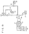
- Fig. 13 shows a testing equipment which is used herein.
- reference numeral 21 is a vertically disposed stainless steel absorbing tube having a length of 1.15 m and an inside diameter of 18 mm.
- Reference numeral 22 is a CO 2 absorbing liquid tank containing a 30% aqueous monoethanolamine solution, and this solution is fed to the top of the absorbing tube 21 through an absorbing liquid inlet 24 by means of a metering pump 23.
- the absorbing liquid is fed to one point on the inner surface of the absorbing tube 21 at a flow rate of 4 liters/hour, and at the time of the downward flow, an expansion degree of the absorbing liquid varies with the members of the inner surfaces.
- the absorbing liquid which has flowed downward in contact with a test gas is led to a liquid reservoir 27.
- a CO 2 concentration of the test gas is analyzed in the vicinity of the gas inlet 25 of the absorbing tube 21 by a CO 2 continuous analyzer 28, and the gas is then brought into contact with the CO 2 absorbing liquid during rising through the absorbing tube 21.
- the test gas is discharged from the system. Every test was made at room temperature (25° C).
- Reference numerals 30, 30, 30 are three gas cylinders filled with a CO 2 gas, a nitrogen gas, and an oxygen gas, respectively.
- Numeral 31. is a gas flow rate controller, and 32 is a switch cock.
- Figs. 14 and 15 show relations between a CO 2 absorption ratio (%, ordinate) and a liquid/gas ratio L/G (liter/m 3 N, abscissa) on the basis of the different members for the gas-liquid contact surfaces.
- Fig. 15 shows a liquid hold up volume (ml/m, ordinate) in the case that the - respective contact surface members are used. It is apparent from Figs.
- Fig. 16 shows a CO 2 , gas absorption device in which tubular structure fillers 40 are arranged instead of the tubular structure fillers 2 in Fig. 1.
- Other members in Fig. 16 have the same reference numerals as in Fig. 1, and they have already described in the first embodiment and so the description regarding them will be omitted.
- a mesh-like member such as a wire mesh may be interposed for the sake of the redispersion of the downward flowing absorbing liquid.
- the present invention is characterized in that the horizontal section of the filler has a shape selected from the group consisting of circles (A), circular arcs or continuously combined circular arcs (B) and straight lines (C) which neither mutually intersect nor contact.
- the horizontal section of the filler comprises only one of these shapes, but it may comprise two or more thereof.
- the shape of the horizontal section of the tubular structure filler 40 is one of the shapes usable in the present invention, and this shape comprises the group of the straight lines which neither mutually intersect nor contact, particularly it comprises parallel lines in this example.
- the tubular structure is constituted of a plurality of vertically arranged.plates, as apparently shown in Fig. 16.
- the arrangement density of these plates should be selected so that the absorbing liquids flowing downward along the vertically or horizontally adjacent plates 13 may not come in contact with each other and so that the flow path resistance of the combustion exhaust gas may not be impaired.
- the plates are arranged at a higher density in consideration of these requirements. This Arrangement density may be adjusted by interposing a spacer between the adjacent plates.
- Fig . 17 shows another example of the filler, i.e., a linear filler 42 in which the shape of a horizontal section comprises straight lines which neither mutually intersect nor contact;
- Fig. 18 shows a circular filler 52; Fig.
- FIG. 19 shows a continuous semicircular arc filler 62; and Fig.20 shows a spiral filler 72 which seems to be continuously combined circular arcs having a gradually increasing (or decreasing) radius.
- the continuous combination of the circular arcs additionally includes a smoothly formed free curve.
- a shape in which another circular arc is combined with the circular arc at a point is excluded from the category of the continuous combination regarding the present invention.
- each of reference numerals 41, 51, 61 and 71 in Figs. 17, 18, 19 and 20 is a CO 2 absorption device.
- the absorbing liquid fed from the top does not get together at a certain position to flow downward in the form of a string, but tends to expand in the horizontal direction of the inner wall, when it flows downward along the inner wall (the gas-liquid contact surface) of the tubular structure. In consequence, a gas-liquid contact efficiency is remarkably improved.
- a CO 2 absorbing test was made, as the simplest case, using a circular absorbing tube (Example), a triangular absorbing tube (Comparative Example 1), and a quadrangular absorbing tube (Comparative Example 2) which were the barrels of absorption devices having an inside diameter of 15 mm and which were made of a transparent acrylic resin. These tubes having the respective shapes were designed so that the total areas of their inside walls might be equal to each other.
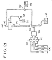
- Fig. 21 shows a testing equipment which is used herein.
- reference numeral 91 is a vertically disposed absorbing tube having a length of 1.15 m.
- Numeral 92 is a CO 2 absorbing liquid tank containing a 30% aqueous monoethanolamine solution, and the CO 2 absorbing liquid is fed to the top of the absorbing tube 91 through an absorbing liquid inlet 94 by means of a metering pump 93.
- the absorbing liquid is constantly fed to the inner wall of the absorbing tube at a flow rate of 4 liters/hour by overflow, as shown in this drawing.
- an.expansion degree of the absorbing liquid, a wet degree of the inside walls and a CO 2 absorbing efficiency vary with the shapes of the above-mentioned absorbing tubes 91.
- the absorbing liquid which has flowed downward in contact with a test gas is led to a liquid reservoir 97.
- a CO 2 concentration of the test gas is analyzed in the vicinity of the gas inlet 95 of the absorbing tube 91 by a CO 2 continuous analyzer.98, and the test gas is then brought into contact with the CO 2 absorbing liquid during rising through the absorbing tube.
- the test gas is discharged from the system. Every test was made at room temperature (25°C).
- Reference numerals 100, 100, 100 are three gas cylinders filled with a CO 2 gas, a nitrogen gas, and an oxygen gas, respectively.
- Numeral 101 is a gas flow rate controller, and 102 is a switch cock.
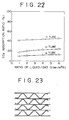
- Fig. 22 shows relations between a CO 2 absorption (%, ordinate) and a liquid/gas ratio L/G (liter/m 3 N, abscissa) on the basis of the different shapäs for the gas-licuid contact surfaces.
- L/G liquid/gas ratio
Landscapes
- Chemical & Material Sciences (AREA)
- Chemical Kinetics & Catalysis (AREA)
- Engineering & Computer Science (AREA)
- Analytical Chemistry (AREA)
- Oil, Petroleum & Natural Gas (AREA)
- General Chemical & Material Sciences (AREA)
- Organic Chemistry (AREA)
- Physics & Mathematics (AREA)
- Thermal Sciences (AREA)
- Mechanical Engineering (AREA)
- General Engineering & Computer Science (AREA)
- Gas Separation By Absorption (AREA)
- Treating Waste Gases (AREA)
- Physical Or Chemical Processes And Apparatus (AREA)
Abstract
Description
- The present invention relates to an apparatus for gas-liquid contact, particularly to an apparatus for gas-liquid contact capable of efficiently bringing a gas into contact with a liquid like a CO2 gas absorption device for removing a CO2 gas from an exhaust gas by bringing the CO2 gas contained in the exhaust gas into contact with a CO2 gas absorbing liquid. Such an apparatus is for example disclosed in EP-A-0501599.
In recent years, a greenhouse effect due to CO2 has been pointed out as one of the causes of a global atmosphere warming phenomenon, and it has been internationally required to urgently take measures for the greenhouse effect in order to protect a global atmospheric environment. The generation source of CO2 lies in every human activity field in which a fossil fuel is burnt, and the exhaust control of CO2 tends to be furher strengened in future. As one of the measures for the exhaust control, for power generation facilities of thermal power plants in which a large amount of the fossil fuel is used, there have been energetically researched a method for removing and collecting CO2 from the combustion exhaust gas of a boiler, and a method for storing C02 without discharging it to the atmosphere.
On the other hand, in a gas-liquid contact technique which is employed in an absorption process of a chemical plant, a bubble cap plate tower and a packed tower have been used so that the gas-liquid contact may be achieved as much as possible. As the filler of the latter, Raschig rings having various shapes have been used.
In the apparatus for the gas-liquid contact for absorbing CO2 in the combustion exhaust gas, it is necessary to efficiently treat a large amount of the gas in a short time.
Therefore, an apparatus for gas-liquid contact is desired in which expansion, contraction and collision of a gas flow are not in a gas passage, no eddy occurs, and unnecessary pressure loss due to the above factors hardly takes place. Moreover, an apparatus for gas-liquid contact is desired which is constituted as simply as possible and by which a gas-liquid contact area and a contact time can be increased to resultingly heighten a contact efficiency.
As the CO2 gas absorotion device for removing CO2 from the combustion exhaust gas, the present inventors have previously suggested a CO2 gas absortion device in which many fillers are arranged so that the gas-liquid contact surfaces of the fillers may be parallel with a gas flow and they comprise tubular structures whose cross section has any of various shapes and whose tubular portions are straight, as shown in Fig. 1 (which shows the whole constitutional view of the CO2 gas absorption device which will also be used in an embodiment of the apparatus for gas-liquid contact of the present invention) (cf. EP-A-0 501 599).
That is, in Fig. 1,reference numeral 1 is a CO2 gas absorption device, andnumerals Reference numeral 3 is a line for transporting a CO2 absorbing liquid,numeral 4 is a liquid dispersing nozzle, 5 is a storage space of the absorbing liquid in which CO2 is absorbed, 6 is a combustion exhaust gas containing CO2, and 7 is a clean exhaust gas from which CO2 is removed.
As described above, any of the various shapes can be employed as the cross section of thefillers 2 comprising the tubular structures, and this cross section may be constituted of one or a combination of these shapes. In thefillers 2 comprising the tubular structures, the flow of the gas is parallel with the absorbing surface (the gas-liquid contact surface). Thus, in the gas flow path, the expansion, contraction and collision of the gas flow are not present, and no eddy occurs, so that the unnecessary pressure loss due to these factors is very small. In this case, the absorbing liquid is held by the absorbing surfaces of thefillers 2 comprising the tubular structures, and the held absorbing liquid is brought into contact with the gas flow to absorb C02 while flowing downward along the surfaces. Therefore, according to this constitution the pressure loss can be remarkably decreased, in contrast to fillers such as conventional Raschig rings.
However, the above-mentioned CO2 gas absorption device has the following problems. - (a) When the absorbing surfaces of the tubular structures which are the fillers are smoothly mirror-finished, the absorbing liquid flows downward along the absorbing surfaces of the tubular structures in the form of a string owing to surface tension or cohesive force, so that it does not expand all over the absorbing surfaces and so the wet area decreases. In consequence, the gas-liquid contact area tends to decrease and the CO2 absorption efficiency also tends to deteriorate inconveniently.
- (b) The unit length of each tubular structure filler in the gas flow direction is restricted in view of manufacture. Therefore, if the fillers having a length of, for example, about 20 m are filled, it is necessary to pile up the tubular structure fillers up to about 20 steps. In this case, a gap is formed between each pair of the tubular structures. When the absorbing liquid flows from upper tubular structures to lower tubular structures, its flow takes the form of a string owing to the above-mentioned gap, so that its dispersibility is impaired. In order to decrease this gap, a high processing precision is required, which leads to increase of cost.
- c) The CO2 gas absorption device has some points to be improved, in the case that the gas-liquid contact surfaces on the inner walls of the tubular structures which are the fillers are mirror-finished. That is, the absorbing liquid flows downward along the gas-liquid contact surfaces of the tubular structures in the form of a string owing to surface
tension or cohesive force without expanding all over the inner walls, so that the wet area (the gas-liquid contact area) decreases, and the residence time of the downward flowing liquid on the gas-liquid contact surfaces is also short. In consequence, the CO2 absorption efficiency is not necessarily satisfied. - (d) As another example of the horizontal section of the tubular structure fillers, there is a section in which many wavy crests (or troughs) and the straight portions come in contact with each other.
- In view of the above-mentioned situations, the present invention has been intended.
One object of the present invention is to provide an apparatus for gas-liquid contact capable of solving the ,above-mentioned problem (a) and improving a gas-liquid contact efficiency by increasing the contact area per unit area of the gas-liquid contact surfaces of tubular structure fillers. - A further object of the present invention is to provide an apparatus for gas-liquid contact capable of solving the above-mentioned problem (b) and improving dispersibility during the downward flow of an absorbing liquid from upper step to lower step of the tubular structure fillers.
A still further object of the present invention is to provide an apparatus for gas-liquid contact capable of solving the above-mentioned problem (c) by the use of a specific material for the gas-liquid contact surfaces of the tubular structure fillers.
Another object of the present invention is to provide an apparatus for gas-liquid contact capable of solving the above-mentioned problem (d) by forming the horizontal section of the tubular structure fillers into a specific shape.
The constitutions of the present invention for achieving the above-mentioned objects are characterized by the following items (1) to (10) in an apparatus for gas-liquid contact comprising tubular structure fillers having straight tubular portions arranged (in the apparatus) in a substantially vertical direction in plural steps so that the gas-licuid contact surfaces of the fillers may be parallel with the flow of the gas, whereby the gas can be brought into contact with the liquid by feeding the liquid from a site above the fillers, allowing the liquid to flow downward along the filler surfaces, and feeding the gas from a site under the fillers. - (1) It is characterized that the gas-liquid contact surfaces of the fillers comprise rough surface portions having a center line average height of 50 µm or more. The center line average height referred to in this specification is defined as a value of micrometers (µm) obtained by the following equation, as standardized in Japanese Industrial Standard JIS B 0601-1982, in the case that a portion of a measurement length ℓ is sampled in the direction of the center line from a roughness curve, the center line of the sampled portion is an X axis, the direction of longitudinal magnification is a Y axis , and the roughness curve is


- (2) It is characterized that the gas-liquid contact surfaces of the fillers comprise porous surface portions having a plurality of orifices.
- (3) It is characterized that the fillers comprise meshes.
- (4) The apparatus for gas-liquid contact of the above-mentioned item (1), (2) or (3) is characterized in that the gas is a combustion exhaust gas and the liquid is a CO2 absorbing liquid.
The function of the present invention makes it possible to increase the gas-liquid contact area of the tubular structures of the fillers arranged in the apparatus for gas-liquid contact and to remarkably improve the gas-liquid contact efficiency.
As described above, according to the present invention, the gas-liquid contact surfaces of the tubular structures are roughly formed, or the tubular structures are made of the porous plates or the meshes, so that the gas-liquid contact area of the tubular structures can be increased and the gas-liquid contact efficiency can be largely improved. - (5) The apparatus for gas-liquid-contact is characterized in that the plural steps of the fillers are separated from each other, and there is interposed, between the steps, a dispersing plate for receiving the liquid downward coming from the upper site of the fillers, dispersing the liquid, and allowing the liquid to downward flow.
- (6) In the apparatus for gas-liquid contact of the item (5), it is characterized that the disdersing plate has a mesh portion.
- (7) In the apparatus for gas-liquid contact of the item (5), it is characterized that the dispersing plate has a porous surface portion with a plurality of orifices.
- (8) In the apparatus for gas-liquid contact of the item (5), it is characterized that the gas is a combustion exhaust gas and the liquid is a CO2 absorbing liquid.
According to the function of the present invention, the liquid which flows downward from the upper tubular structure is dispersed by the dispersing plate and then fed to the lower tubular structure. Therefore, it is possible to substantially largely indrease the gas-liquid contact area of the tubular structures and to remarkably improve the gas-liquid contact efficiency.
As described above, according to the present invention, the dispersing plate is interposed between the tubular structures, so that the liquid downward coming from the upper tubular structure can be dispersed and then fed to the lower tubular structure. Moreover, because a high precision is not required in manufacturing the respective tubular structures, it is possible to decrease the manufacturing cost.
As described above, according to the present invention, the liquid does not flow downward in the form of a string along the gas-liquid contact surface but it widely expands on the contact surface, so that the residence time of the downward flowing liquid can be prolonged, and in consequence, the gas-liquid contact efficiency can be improved. - (9) In the apparatus for gas-liquid contact, it is characterized that the horizontal section of the fillers has a shape selected from the group consisting of a circle (A), a circular. arc or a continous. combination of circular arcs (B) and straight lines which do not mutually intersect or contact (C).
- (10) In the apparatus for gas-liquid contact of the item (9), it is characterized that the gas is a combustion exhaust gas and the liquid is a CO2 absorbing liquid.
- According to the present invention, the gas-liquid contact area on the inner walls of the fillers arranged in the apparatus for gas-liquid contact can be increased, and the residence time of the downward flowing liquid can be prolonged, whereby the gas-liquid contact efficiency can be remarkably improved.
In addition, according to the present invention, the liquid does not flow downward along the gas-liquid contact surface in the form of a string, but it widely expands on the contact surface, so that the residence time of the downward flowing liquid is prolonged and consequently the gas-liquid contact efficiency can be noticeably improved. -
- Fig. 1 is a whole perspective view showing a CO2 gas absorption device for use in an embodiment of the present invention and its related CO2 gas absorption device;
- Fig. 2 is a perspective view showing a tubular structure arranged in the CO2 gas absorption device;
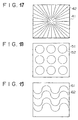
- Fig. 3 is an illustrative view of the rough surface of the tubular structure for use in an embodiment of the present invention;
- Fig. 4 is an illustrative view of the rough surface of the other tubular structure;
- Fig. 5 is an illustrative view of the rough surface of the still other tubular structure;
- Fig. 6 is an illustrative view showing the water repellency of a conventional tubular structure;
- Fig. 7 is an illustrative view of the wettability of an absorbing liquid on the tubular structure in the first embodiment of the present invention;
- Fig. 8 is an illustrative view of the other tubular structure;
- Fig. 9 is an illustrative view of the still other tubular structure;
- Fig. 10 is a constitutional view in which a dispersing plate is interposed between the tubular structures;
- Fig. 11 is an illustrative view of the conventional flow of the absorbing liquid in the case that no dispersing plate is used;
- Fig. 12 is an illustrative view of the flow of the absorbing liquid in the case that a dispersing is provided;
- Fig. 13 is an illustrative view of a testing equipment for inspecting the effect of the apparatus for gas-liquid contact according to the present invention;
- Fig. 14 is a diagram showing test results which elucidate differences of CO2 absorption efficiency due to different materials for the gas-liquid contact surface;
- Fig. 15 is a diagram showing test results which elucidate differences of a held liquid volume due to different materials for the gas-liquid contact surface;
- Fig. 16 is a whole perspektive view of a CO2 gas absorption device to which an apparatus for gas-liquid contact regarding an other embodiment of the present invention is applied;
- Fig. 17 is an illustrative view of the horizontal section of the tubular structure having straight lines which do not mutually intersect or contact in the embodiment of Fig. 16;
- Fig. 18 is an illustrative view of the horizontal section of the tubular structure having circles in the embodiment of Fig. 16;
- Fig. 19 is an illustrative view of the horizontal section of the tubular structure having connected semi-circular arcs in the embodiment of Fig. 16;
- Fig. 20 is an illustrative view of the horizontal section of the tubular structure having spirals in the embodiment of Fig. 16;
- Fig. 21 is an illustrative view of a testing equipment for inspecting an effect of the embodiment of Fig. 16 of the apparatus for gas-liquid contact;
- Fig. 22 is a diagram showing test results which elucidate differences of CO2 absorbing efficiency in the case that absorbing tubes having different shapes of the horizontal section are used; and
- Fig. 23 is an illustrative view of the shape of the horizontal section of the other tubular structure filler for use in the CO2 gas absorption device in Fig. 1.
- Now, suitable embodiments of the present invention will be exemplarily described in detail in reference to drawings.
As the first embodiment of an apparatus for gas-liquid contact of the present invention, reference will be made to a C02 gas absorption device for removing CO2 from a combustion exhaust gas by bringing the combustion exhaust gas containing CO2 into contact with a CO2 absorbing liquid, in reference to Figs. 1 to 9. - In Fig. 1,
tubular structure fillers 2 are vertically arranged in the form of plural steps in a CO2absorption device body 1, and these fillers have an optional shape in a horizontal section and have straight tubular portions.
In Fig. 1, the horizontal section of thetubular structure fillers 2 shows the shape of lattice. Theapparatus body 1 is equipped with a CO2 absorbingliquid transport line 3 for connecting aliquid dispersing nozzle 4 in the top of thebody 1 to an absorbingliquid storage space 5 on the,bottom of thebody 1. An absorbing liquid reproduction process (not shown) for removing CO2 from the absorbing liquid to improve the absorbing capacity may be provided in the middle of thetransport line 3. Theliquid dispersing nozzle 4 is installed so as to disperse the CO2 absorbing liquid delivered through thetransport line 3 to thefillers 2 as uniformly as possible. On the bottom of theapparatus body 1, there is provided an absorbingliquid storage space 5 for storing the CO2 absorbing liquid which absorbs CO2 while the liquid is downward flowing through thefillers 2. An opening, through which acombustion exhaust gas 6 containing CO2 is introduced into theapparatus body 1, is formed on a side of the lower portion of theapparatus body 1. At the top of theapparatus body 1, there is formed an opening through which a clean exhaust gas 7 is discharged to the outside, and this clean exhaust gas 7 is obtained by removing CO2 from the combustion exhaust gas with the CO2 absorbing liquid while the gas flows upward through thefillers 2.
Fig. 2 shows an enlarged partial view of thetubular structure filler 2. Thefiller 2 is formed into a tubular structure having a lattice-like horizontal section, and through thistubular structure filler 2, theexhaust gas 6 lcan flow upward from the bottom of theapparatus body 1 and the fed CO2 absorbing liquid can also flow downward from theliquid dispersing nozzle 4. The inside walls of the tubular portions constitute absorbing surfaces (gas-liquid contact surfaces) on which thecombustion exhaust gas 6 is reacted with the CO2 absorbing liquid.
Thefiller 2 is constituted of porcelaneoustubular structures 21 having one lattice side length De of, for example, 15 mm which are laterally arranged as shown byreference numerals filler 2 has, for example, an area of 300 mm2 and a length of 500 mm. Thefillers 2 are vertically arranged in the form of, for example, 20 stages in theapparatus body 1.
According to thefillers 2 comprising the abovementioned tubular structures, the gas flows in parallel with the absorbing surfaces, and expansion, contraction and collision of the gas flow and an eddy scarcely occur in a gas path, so that pressure loss due to these factors can be sufficiently inhibited. - The shape of the tubular structure 2' is not restricted to the lattice in Fig. 2, and for example, hexagon, rectangle, triangle and U shape are usable, as long as they form the gas parallel flow. Moreover, with regard to a material for the tubular structure 2', a porcelain, a metal, a ceramic fiber such as silica fiber and a plastic such as polyethylene are usable, so long as they are not corroded or swelled by the CO2 absorbing liquid. As for a manufacturing method, the structure shown in Fig. 2 can usually be manufactured by an extrusion molding method, but a combination of a flat plate and a molding plate or a corrugate machine molding method is also applicable. Anyway, an economical manufacturing method can be selected in accordance with the shape and material.
A feature of the present invention is that the absorbing surfaces, i.e.,the gas-liquid contact surfaces of the tubular structures 2' are treated in a rough state so as to have a center line average height of 50 µm or more. The rough-surface treatment is carried out by sandblasting, depending upon a material of the tubular structures. That is, the roughness of the absorbing surface is increased by blowing sand on the absorbing surfaces. This roughness can be adjusted by changing a grain diameter of the sand and a blowing time. Instead of the sand, it is also possible to use particles of a plastic, silicon or a metal, depending upon the material of the absorbing surfaces. Alternatively, instead of blowing the sand to the absorbing surfaces, it is also possible to apply a coating material including the sand to the absorbing surfaces, depending upon the gas to be treated and the liquid. The above-mentioned center line average height is preferably in the range of from 50 to 100 um. The rough surface treatment may be achieved by a chemical treatment, depending upon the material of the absorbing surfaces. When using, for example, stainless steel as the material of the tubular structures 2', FeCl3, HCl or HCl + H202 can be used as chemicals for the chemical treatment.
The absorbing surfaces are corroded with these chemicals to become properly rough. A degree of the corrosion is determined by a chemical concentration x a dipping time x a temperature.
Table 1 shows chemical treatment conditions, treatment results and evaluations.Table 1 Chemicals Conc., Temp. and Time Surface Evaluation FeCl 3 30% - 40-60°C - 2-10 min See Fig. 3 △ HCl 30% - 40-60°C - 5-10 min See Fig. 4 ○ HCl + H2O2 35+1% - 100°C* - 1 min or less See Fig. 5 △ * The temperature was raised to 100°C by heat generation. - When the absorbing surfaces were treated with 30% FeCl3 at a temperature of 40-6O°C for 2-10 minutes, holes 2a and
pitchings 2b were formed on the absorbing surfaces, so that the surfaces were considerably rough, as shown in Fig. 3.
Next, when the absorbing surfaces were treated with 35% HCl at a temperature of 20-40°C for 5-10 minutes, the absorbing surfaces were properly rough, as shown in Fig. 4. Moreover, when 1% H202 was added to 35% HCl to generate heat and the absorbing surfaces were treated for 1 minute or less at a raised temperature of 100°C, the absorbing surfaces were not so rough, as shown in Fig. From these results, it is apparent that the treatment using HCl is most preferable.
Figs. 6 and 7 show a comparison between the effect of the absorbing surface treated with HCl of the above chemicals and that of a conventional absorbing surface. Fig. 6 shows a state of the absorbing surface in the case that the CO2 absorbing liquid comprising an aqueous monoethanolamine solution was sprayed on a mirror finished surface (center line average height = 1 µm)plate 2c of stainless steel (JIS indication: SUS304; austenite) and then allowed to flow downward. In this case, it was impossible to increase a gas-liquid contact area, because the absorbing liquid 2d was repelled to flow in the form of a string on the absorbing surface. On the contrary, when the absorbing surface of the stainless steel plate was roughly formed in the above-mentioned manner, the absorbing liquid 2d expanded on the roughly formed absorbingsurface 2e, whereby the gas-liquid contact area could be increased, as shown in Fig. 7.
Next, another embodiment of the present invention will be described. In this embodiment, the tubular structure 2' is constituted of aporous plate 8 provided with a large number of small holes, as shown in Fig. 8. A rate of the hole,area of theporous plate 8 is preferably 20% or less. The tubular structure 2' may be formed in the shape of a lattice in its horizontal section as described above, or it may be formed in the shape of hexagon, rectangle, triangle or U shape. Fig. 8 shows an embodiment in which the horizontal section is formed into a triangular wavy shape. According to this embodiment, the absorbing liquid easily remains in the small holes of the porous plate to prolong a retention time. Therefore, the absorbing liquid can be prevented from flowing on the absorbing surface in the form of a string to increase the gas-liquid contact area. In consequence, it is possible to improve the C02 absorbing efficiency.
Next still another embodiment of thepresent invention 1 will be described. In this embodiment, the tubular structure 2' is constituted of amesh 9 comprising a wire mesh, as shown in Fig. 9. According to this embodiment, the absorbing liquid can reside in the mesh of the mesh for a long time owing to surface tension or cohesive force, and the diffusion of the absorbing liquid can be easily achieved on the absorbing surface. Therefore, this embodiment also makes it possible to increase the gas-liquid contact area and to improve the CO2 absorbing efficiency. Even if the mesh of a plastic or another material is used instead of the wire mesh, a similar effect can be obtained. No particular restriction is put on a weaving manner of the mesh, and plain weave, twill weave or the like can be employed. The mesh may be disposed so that the wires of the mesh may have a suitable angle to the ground. The size of the mesh to be selected is preferably 3 mesh or more, more preferably 8 mesh or more - As the other embodiment of the apparatus for gas-liquid contact of the present invention, a CO2 gas absorption device for removing CO2 from a combustion exhaust gas by bringing the combustion exhaust gas containing CO2 into contact with a CO2 absorbing liquid will be described in reference to drawings (Figs. 1, 2, and 10 to 12).
The description of Figs. 1 and 2 has been made in the above-mentioned first embodiment, and so it will be omitted.
The present invention is characterized in that a dispersingplate 10 is interposed betweentubular structure fillers 2 vertically arranged in the form of many steps, as shown in the cross section of Fig. 10. The dispersingplate 10 is constituted of, for example, a porous plate. A rate of the hole area of the porous plate (a rate of the hole area to the entire area inclusive of the hole area) is preferably 80% or more in order to prevent the increase of pressure loss at the time of the passage of the gas. The shape of the holes of the porous plate is not limited to a circle, and a deformed shape such as a star is also acceptable. Fig. 11 shows the flow of the absorbing liquid in the case that any dispersing plate is not interposed between the vertically arrangedtubular structure fillers filler 2 in the form of strings, so that the dispersibility of the liquid is impaired. In particular, if a space between thefillers
On the contrary, Fig. 12 shows a case where the dispersingplate 10 is interposed between thefillers upper filler 2 hits against the dispersingplate 10 and is then dispersed thereon again by the dispersingplate 10. Therefore, a gas-liquid contact area can be increased on the absorbing surfaces of thefiller 2, so that a CO2 absorbing efficiency can be improved. When the holes of the porous plate are formed in the shape of a star, the disturbance of the passage of the gas through the holes 11 can be prevented by the passage of the absorbing liquid through the holes 11.
As another embodiment of the present invention, the dispersingplate 10 may be constituted of a wire mesh. Even in this embodiment, about the same effect as in the preceding embodiment can be obtained. In this case, the passage of the gas through the mesh is scarcely prevented by the passage of the absorbing liquid through the mesh. Instead of the wire mesh, a mesh of a plastic or the like may be used.
The effectiveness of the present invention is apparent from the above description, but the dispersibility of the absorbing liquid flowing from the top was observed at ordinary temperature and atmospheric pressure by the use of a 30% aqueous monoethanolamine solution as the CO2 absorbing liquid, the porcelaneous tubular structures having an area of 300 mm2 , a length of 500 mm and De of 15 mm, and a wire mesh as the dispersing plate. As a result, it could be confirmed that the absorbing liquid fed to the upper tubular structures was substantially uniformly dispersed at the exit of the lower tubular structures and then flowed downward, in the case that the wire mesh was interposed between the two tubular structures and these tubular structures were then uprightly assembled. In consequence, it can be confirmed that the CO2 absorbing efficiency can remarkably be improved by the present invention. - In order to confirm a gas-liquid contact efficiency in the case that a member obtained by stacking the above-mentioned mesh on the surface of the above-mentioned plate was used on a gas-liquid contact surface, a model test was made, and the performance of a cylindrical inside surface formed with the above-mentioned member was compared with that of another cylindrical inside surface formed with another member.
Fig. 13 shows a testing equipment which is used herein. In Fig. 13,reference numeral 21 is a vertically disposed stainless steel absorbing tube having a length of 1.15 m and an inside diameter of 18 mm. Three samples are used: a stainless steel tube in which its inside surface is chemically treated by immersing it in a 35% hydrochloric acid solution at a temperature of 30°C for 10 minutes (Comparative Example 1), a stainless steel tube treated by sandblasting (center line average height = 1 µm, Comparative Example 2), and a stainless steel tube to which a 20-mesh wire mesh is attached (Example).Reference numeral 22 is a CO2 absorbing liquid tank containing a 30% aqueous monoethanolamine solution, and this solution is fed to the top of the absorbingtube 21 through an absorbingliquid inlet 24 by means of ametering pump 23. The absorbing liquid is fed to one point on the inner surface of the absorbingtube 21 at a flow rate of 4 liters/hour, and at the time of the downward flow, an expansion degree of the absorbing liquid varies with the members of the inner surfaces. The absorbing liquid which has flowed downward in contact with a test gas is led to aliquid reservoir 27. on the other hand, the test gas having a CO2 concentration of 9.7-9.8 vol% (nitrogen concentration = 90.2-90.3 vol%) is fed at a flow rate of 2 m3 /hour to the absorbingtube 21 through agas inlet 25 provided at a lower portion of the absorbingtube 21
A CO2 concentration of the test gas is analyzed in the vicinity of thegas inlet 25 of the absorbingtube 21 by a CO2continuous analyzer 28, and the gas is then brought into contact with the CO2 absorbing liquid during rising through the absorbingtube 21. After the CO2 concentration of the test gas has been similarly analyzed again in front of agas outlet 29, the test gas is discharged from the system. Every test was made at room temperature (25° C).
Reference numerals Numeral 31. is a gas flow rate controller, and 32 is a switch cock.
The obtained results of this test are shown in Figs. 14 and 15. Fig. 14 shows relations between a CO2 absorption ratio (%, ordinate) and a liquid/gas ratio L/G (liter/m3 N, abscissa) on the basis of the different members for the gas-liquid contact surfaces. Moreover, Fig. 15 shows a liquid hold up volume (ml/m, ordinate) in the case that the - respective contact surface members are used.
It is apparent from Figs. 14 and 15 that the stainless steel absorbing tube provided on the inside surface thereof with the 20-mesh wire mesh is much more excellent in the absorption ratio and the liquid hold up volume than other members, the aforesaid wire mesh being correspond to the member of the present invention comprising the plate and the mesh stuck on the surface thereof. After the test, the inside walls of the absorbing tubes are inspected. As a result, wet ratios are 60% in Comparative Example 1, 26% in Comparative Example 2, and 81% in Example - As a fourth embodiment of the apparatus for gas-liquid contact of the present invention, an example which is applied to a CO2 gas absorption device for removing CO2 from a combustion exhaust gas by bringing the combustion exhaust gas containing CO2 into contact with a CO2 absorbing liquid will be described in reference to the drawings (Figs. 16 to 22).
Fig. 16 shows a CO2, gas absorption device in which tubularstructure fillers 40 are arranged instead of thetubular structure fillers 2 in Fig. 1. Other members in Fig. 16 have the same reference numerals as in Fig. 1, and they have already described in the first embodiment and so the description regarding them will be omitted.
Between the plural steps of thefillers 40, a mesh-like member such as a wire mesh may be interposed for the sake of the redispersion of the downward flowing absorbing liquid. The present invention is characterized in that the horizontal section of the filler has a shape selected from the group consisting of circles (A), circular arcs or continuously combined circular arcs (B) and straight lines (C) which neither mutually intersect nor contact. In general, the horizontal section of the filler comprises only one of these shapes, but it may comprise two or more thereof.
In Fig. 16, the shape of the horizontal section of thetubular structure filler 40 is one of the shapes usable in the present invention, and this shape comprises the group of the straight lines which neither mutually intersect nor contact, particularly it comprises parallel lines in this example. In this case, the tubular structure is constituted of a plurality of vertically arranged.plates, as apparently shown in Fig. 16. The arrangement density of these plates should be selected so that the absorbing liquids flowing downward along the vertically or horizontally adjacent plates 13 may not come in contact with each other and so that the flow path resistance of the combustion exhaust gas may not be impaired. Preferably, the plates are arranged at a higher density in consideration of these requirements. This Arrangement density may be adjusted by interposing a spacer between the adjacent plates.
Fig . 17 shows another example of the filler, i.e., alinear filler 42 in which the shape of a horizontal section comprises straight lines which neither mutually intersect nor contact; Fig. 18 shows acircular filler 52; Fig. 19 shows a continuoussemicircular arc filler 62; and Fig.20 shows a spiral filler 72 which seems to be continuously combined circular arcs having a gradually increasing (or decreasing) radius. The continuous combination of the circular arcs additionally includes a smoothly formed free curve. However, a shape in which another circular arc is combined with the circular arc at a point is excluded from the category of the continuous combination regarding the present invention. Incidentally, each ofreference numerals
When the filler having the shape of this example is used, the absorbing liquid fed from the top does not get together at a certain position to flow downward in the form of a string, but tends to expand in the horizontal direction of the inner wall, when it flows downward along the inner wall (the gas-liquid contact surface) of the tubular structure. In consequence, a gas-liquid contact efficiency is remarkably improved.
In order to confirm a gas-liquid contact efficiency in the case that a filler having a horizontal section shape of this embodiment was used, a CO2 absorbing test was made, as the simplest case, using a circular absorbing tube (Example),
a triangular absorbing tube (Comparative Example 1), and a quadrangular absorbing tube (Comparative Example 2) which were the barrels of absorption devices having an inside diameter of 15 mm and which were made of a transparent acrylic resin. These tubes having the respective shapes were designed so that the total areas of their inside walls might be equal to each other.
Fig. 21 shows a testing equipment which is used herein.
In Fig. 21,reference numeral 91 is a vertically disposed absorbing tube having a length of 1.15 m.Numeral 92 is a CO2 absorbing liquid tank containing a 30% aqueous monoethanolamine solution, and the CO2 absorbing liquid is fed to the top of the absorbingtube 91 through an absorbingliquid inlet 94 by means of ametering pump 93. The absorbing liquid is constantly fed to the inner wall of the absorbing tube at a flow rate of 4 liters/hour by overflow, as shown in this drawing. At the time of the downward flow, an.expansion degree of the absorbing liquid, a wet degree of the inside walls and a CO2 absorbing efficiency vary with the shapes of the above-mentionedabsorbing tubes 91. The absorbing liquid which has flowed downward in contact with a test gas is led to aliquid reservoir 97. On the other hand, the test gas having a CO2 concentration of 9.7-9.8 vol% (nitrogen concentration = 90.2-90.3 vol%) is fed at a flow rate of 2 m3 /hour to the absorbingtube 91 through agas inlet 95 provided at a lower portion of the absorbingtube 91. A CO2 concentration of the test gas is analyzed in the vicinity of thegas inlet 95 of the absorbingtube 91 by a CO2 continuous analyzer.98, and the test gas is then brought into contact with the CO2 absorbing liquid during rising through the absorbing tube. After the CO2 concentration of the test gas has been similarly analyzed again in front,of a gas outlet 99, the test gas is discharged from the system. Every test was made at room temperature (25°C).
Reference numerals Numeral 101 is a gas flow rate controller, and 102 is a switch cock.
The obtained results of this test are shownin Fig. 22. Fig. 22 shows relations between a CO2 absorption (%, ordinate) and a liquid/gas ratio L/G (liter/m3 N, abscissa) on the basis of the different shapäs for the gas-licuid contact surfaces.
As is apparent from Fig. 22, when the circular absorbing tube having the filler horizontal section shape of this embodiment is used, a CO2 absorption ratio is much more excellent than in the cases of the quadrangular tube and the triangulär tube. Moreover, during the absorbing test, a downward flow state of the absorbing liquid was observed. As a result, it was apparent that the inner wall of the circular absorbing tube was entirely wetted with the absorbing liquid and a wet rate was 100%. On the contrary, in the quadrangular tube and the triangular tube, the absorbing liquid tended to get together and flow only at corners and the wet rates of the both tubes were about 20%.
That is, the absorbing liquid which is fed to the tubular structure from the liquid dispersing
Claims (8)
- An apparatus for gas-liquid contact comprising tubular structure fillers having straight tubular portions, said tubular structure fillers arranged in a substantially vertical direction in the form of plural steps within the apparatus so that the gas-liquid contact surfaces of the fillers are parallel with the flow of the gas, whereby the gas is brought into contact with the liquid by feeding the liquid from a site above the fillers, allowing the liquid to flow downwardly along the filler surfaces, and feeding the gas from a site under the fillers,
said apparatus being characterized in that the gas-liquid contact surfaces of the fillers (2) comprise a rough surface portion having a center line average height of 50 µm or more, or a porous surface portion having a plurality of orifices (2a), or a mesh. - An apparatus for gas-liquid contact comprising tubular structure fillers having straight tubular portions, said tubular structure fillers arranged in a substantially vertical direction in the form of plural steps within the apparatus so that the gas-liquid contact surfaces of the fillers are parallel with the flow of the gas, whereby the gas is brought into contact with the liquid by feeding the liquid from a site above the fillers, allowing the liquid to flow downwardly along the filler surfaces, and feeding the gas from a site under the fillers,
said apparatus being characterized in that said plural steps of the fillers (2) are separaten from each other, and there is interposed, between the steps, a dispersing plate (10) for receiving the liquid flowing downwardly from the upper site of the fillers (2), dispersing the liquid, and allowing the liquid to flow downwardly. - The apparatus for gas-liquid contact according to claim 2,
wherein the dispersing plate (10) has a mesh portion. - The apparatus for gas-liquid contact according to claim 2,
wherein the dispersing plate (10) has a porous surface portion with a plurality of orifices. - The apparatus for gas-liquid contact according to claim 1 or 2,
wherein the gas is a combustion exhaust gas and the liquid is a CO2 absorbing liquid. - The apparatus for gas-liquid contact according to any one of claims 1-5,
wherein the gas-liquid contact surfaces of the fillers (2) comprise a rough surface portion having a center line average height of 50 µm or more. - The apparatus for gas-liquid contact according to any one of claims 1-5,
wherein the gas-liquid contact surfaces of the fillers (2) comprise a porous surface portion having a plurality of orifices (2a). - The apparatus for gas-liquid contact according to any one of claims 1-5,
wherein the fillers (2) comprise a mesh.
Applications Claiming Priority (13)
| Application Number | Priority Date | Filing Date | Title |
|---|---|---|---|
| JP4098/93 | 1993-01-13 | ||
| JP409893 | 1993-01-13 | ||
| JP409793 | 1993-01-13 | ||
| JP05004098A JP3073350B2 (en) | 1993-01-13 | 1993-01-13 | Gas-liquid contact device |
| JP5004097A JPH06210121A (en) | 1993-01-13 | 1993-01-13 | Gas-liquid contacting device |
| JP4097/93 | 1993-01-13 | ||
| JP59844/93 | 1993-03-19 | ||
| JP5984493 | 1993-03-19 | ||
| JP59845/93 | 1993-03-19 | ||
| JP5059844A JPH06269628A (en) | 1993-03-19 | 1993-03-19 | Gas and liquid contact device |
| JP5984593 | 1993-03-19 | ||
| JP5059845A JPH06269629A (en) | 1993-03-19 | 1993-03-19 | Gas/liquid contact device |
| EP94250001A EP0606964B1 (en) | 1993-01-13 | 1994-01-03 | Apparatus for gas-liquid contact |
Related Parent Applications (2)
| Application Number | Title | Priority Date | Filing Date |
|---|---|---|---|
| EP94250001A Division EP0606964B1 (en) | 1993-01-13 | 1994-01-03 | Apparatus for gas-liquid contact |
| EP94250001.8 Division | 1994-01-03 |
Publications (3)
| Publication Number | Publication Date |
|---|---|
| EP0803277A2 true EP0803277A2 (en) | 1997-10-29 |
| EP0803277A3 EP0803277A3 (en) | 1997-12-29 |
| EP0803277B1 EP0803277B1 (en) | 2002-04-17 |
Family
ID=27454010
Family Applications (2)
| Application Number | Title | Priority Date | Filing Date |
|---|---|---|---|
| EP97250219A Expired - Lifetime EP0803277B1 (en) | 1993-01-13 | 1994-01-03 | Apparatus for gas-liquid contact |
| EP94250001A Expired - Lifetime EP0606964B1 (en) | 1993-01-13 | 1994-01-03 | Apparatus for gas-liquid contact |
Family Applications After (1)
| Application Number | Title | Priority Date | Filing Date |
|---|---|---|---|
| EP94250001A Expired - Lifetime EP0606964B1 (en) | 1993-01-13 | 1994-01-03 | Apparatus for gas-liquid contact |
Country Status (7)
| Country | Link |
|---|---|
| US (1) | US5536454A (en) |
| EP (2) | EP0803277B1 (en) |
| KR (1) | KR970003061B1 (en) |
| CN (1) | CN1048416C (en) |
| DE (2) | DE69409264T2 (en) |
| DK (1) | DK0803277T3 (en) |
| NO (1) | NO309026B1 (en) |
Cited By (3)
| Publication number | Priority date | Publication date | Assignee | Title |
|---|---|---|---|---|
| WO2001045817A1 (en) * | 1998-07-02 | 2001-06-28 | ABB Fläkt Aktiebolag | Liquid distribution in a contact device |
| US6476162B1 (en) | 2001-06-06 | 2002-11-05 | Nippon Shokubai Co., Ltd. | Method for preventing easily polymerizing substance from polymerization and method for production of (meth) acrylic acid or ester thereof |
| FR2983737A1 (en) * | 2011-12-13 | 2013-06-14 | IFP Energies Nouvelles | METHOD FOR DEACIDIFYING GAS WITH IMPLEMENTATION OF MONOLITHLY CONTACTOR |
Families Citing this family (29)
| Publication number | Priority date | Publication date | Assignee | Title |
|---|---|---|---|---|
| JP3625901B2 (en) * | 1995-06-30 | 2005-03-02 | 三菱電機株式会社 | Method and apparatus for automatically optimizing servo control system |
| DE19530329A1 (en) * | 1995-08-17 | 1997-02-20 | Basf Ag | Packing material for mass transfer columns and process for its production |
| DE19611976A1 (en) * | 1996-03-26 | 1997-10-02 | Basf Ag | Process and reactor for carrying out material conversions with catalysts suspended in liquids |
| RU2133140C1 (en) * | 1998-03-05 | 1999-07-20 | Пензенская государственная архитектурно-строительная академия | Compact heat- and mass-transfer apparatus |
| DE69934262T2 (en) * | 1999-12-21 | 2007-05-24 | Alstom | DISTRIBUTION OF GAS AND LIQUID IN A CONTACT DEVICE |
| US6517058B1 (en) | 2000-03-02 | 2003-02-11 | Sandkuhl Clay Works, Inc. | Fill packs for use in heat and mass transfer devices |
| GB2402087B (en) * | 2002-03-01 | 2005-10-05 | Oiko Group Ltd | Device and method for removing pollutants from exhaust gases |
| US7011048B2 (en) * | 2004-07-22 | 2006-03-14 | Ener1, Inc. | Method and apparatus for liquid fuel preparation to improve combustion |
| US20060251547A1 (en) * | 2005-05-05 | 2006-11-09 | Windes Larry C | Family of stationary film generators and film support structures for vertical staged polymerization reactors |
| KR100682452B1 (en) * | 2005-08-03 | 2007-02-15 | (주)에이엠티퍼시픽 | Gas-liquid contactor for increased capacity of dual flow tray |
| KR100669032B1 (en) * | 2006-08-21 | 2007-01-16 | 금호환경 주식회사 | Fluid mixing device for air pollutant removal |
| FR2913897B1 (en) * | 2007-03-20 | 2009-11-20 | Inst Francais Du Petrole | FLUID STRUCTURE FOR FLUID CONTACT COLUMN AND METHOD OF MANUFACTURING THE SAME. |
| DE102007040892A1 (en) | 2007-08-24 | 2009-02-26 | Fsp Fluid Systems Partners Holding Ag | Curled or folded flat material |
| US8245863B2 (en) * | 2008-01-18 | 2012-08-21 | Dennis Pearlstein | Explosion resistant gas tank design |
| KR101166231B1 (en) * | 2009-04-01 | 2012-07-17 | 양사헌 | Gas-liquid contact plate |
| EP2489421B1 (en) | 2011-02-18 | 2021-03-31 | General Electric Technology GmbH | A wet scrubber for cleaning an effluent gas comprising an inlet gas distributor with a diffusor |
| JP5704238B2 (en) | 2011-07-28 | 2015-04-22 | 株式会社Ihi | Gas separator and filler |
| JP6180704B2 (en) | 2011-12-12 | 2017-08-16 | 日本リファイン株式会社 | Gas-liquid contact device |
| JPWO2014017111A1 (en) * | 2012-07-27 | 2016-07-07 | 株式会社Ihi | Gas separator and filler |
| EP3127605B1 (en) | 2014-04-01 | 2020-06-03 | IHI Corporation | Method of manufacturing packing and packing |
| DE102014215012A1 (en) * | 2014-07-30 | 2016-02-04 | Robert Bosch Gmbh | Gas cleaning unit for a battery system |
| RU2568706C1 (en) * | 2014-10-17 | 2015-11-20 | Игорь Анатольевич Мнушкин | Contact device for heat and mass exchange and separation of phases in partitioned cross flow packed columns in gas-liquid and liquid-liquid systems |
| JP6641844B2 (en) | 2015-09-30 | 2020-02-05 | 株式会社Ihi | Filler |
| WO2018025757A1 (en) | 2016-08-01 | 2018-02-08 | 株式会社Ihi | Filler and manufacturing method therefor |
| AU2019214659B2 (en) | 2018-01-30 | 2021-07-15 | Ihi Corporation | Packing, method for manufacturing same, and liquid film-forming structure |
| EP3931922B1 (en) * | 2019-02-25 | 2022-11-09 | L'air Liquide, Societe Anonyme Pour L'etude Et L'exploitation Des Procedes Georges Claude | Apparatus for exchanging heat and material |
| CN112023868A (en) * | 2020-09-08 | 2020-12-04 | 北京化工大学 | Novel efficient wall-flow-free regular silk screen packing |
| WO2022241049A1 (en) * | 2021-05-11 | 2022-11-17 | Carbon Engineering Ltd. | Gas-liquid contactor with packing for capturing carbon dioxide |
| EP4547809A1 (en) * | 2022-06-30 | 2025-05-07 | Prote-In S.r.l. | Bioreactor and process for microbial gas fermentation |
Family Cites Families (28)
| Publication number | Priority date | Publication date | Assignee | Title |
|---|---|---|---|---|
| US1291833A (en) * | 1917-11-03 | 1919-01-21 | Ernest R Godward | Method of and apparatus for carburation. |
| US2253261A (en) * | 1939-08-09 | 1941-08-19 | Northern Blower Company | Dust collector |
| US2665123A (en) * | 1949-05-26 | 1954-01-05 | C D Patents Ltd | Apparatus for treating gases with liquids |
| US2783982A (en) * | 1955-01-27 | 1957-03-05 | Kahl Carl H William | Evaporative cooler with tower air flow |
| US2911056A (en) * | 1957-03-05 | 1959-11-03 | Walter L Edel | Absorber |
| US2917292A (en) * | 1957-03-29 | 1959-12-15 | Dow Chemical Co | Assemblies of extended surface elements for gas-liquid contact apparatus |
| US3155153A (en) * | 1959-07-10 | 1964-11-03 | Lizenzia A G | Rotatable body for transfer of moisture or/and heat |
| US3101382A (en) * | 1960-01-14 | 1963-08-20 | Carrier Corp | Gas and liquid contact apparatus |
| US3150211A (en) * | 1961-05-09 | 1964-09-22 | British Columbia Res Council | Gas-liquid contacting apparatus |
| US3353799A (en) * | 1963-05-22 | 1967-11-21 | American Radiator & Standard | Fluid treating apparatus and packing construction therefor |
| FR1377537A (en) * | 1963-09-26 | 1964-11-06 | Tissmetal Lionel Dupont | packing element for exchange columns between two fluids |
| US3316064A (en) * | 1964-04-30 | 1967-04-25 | Hitachi Ltd | Apparatus for continuous polycondensation reaction |
| US3502445A (en) * | 1966-11-02 | 1970-03-24 | Union Oil Co | Apparatus for mixing fluids in concurrent downflow relationship |
| US3523762A (en) * | 1967-05-19 | 1970-08-11 | Universal Oil Prod Co | Baffled chamber for a plurality of contact beds to preclude diffused fluid flow |
| US3595626A (en) * | 1968-11-14 | 1971-07-27 | Du Pont | Ceramic fillers and covers for packed beds |
| CH520309A (en) * | 1970-08-20 | 1972-03-15 | Bbc Brown Boveri & Cie | Equipment for evaporative cooling towers with trickle walls |
| US3723072A (en) * | 1971-03-12 | 1973-03-27 | Universal Oil Prod Co | Fluid contacting apparatus |
| CH537208A (en) * | 1971-04-29 | 1973-07-13 | Sulzer Ag | Mixing device for flowable media |
| US4382046A (en) * | 1981-09-22 | 1983-05-03 | Ceramic Cooling Tower Company | Water cooling tower with layers of multi-cell tiles and spacers |
| DD232393A3 (en) * | 1984-08-01 | 1986-01-29 | Leipzig Chemieanlagen | FLUID DISTRIBUTORS FOR GAS / STEAM LIQUID CONTACT APPARATES |
| CH664091A5 (en) * | 1985-01-30 | 1988-02-15 | Sulzer Ag | PACKING BODY MADE OF THIN, FILM-LIKE MATERIAL FOR FABRIC AND HEAT EXCHANGE COLUMNS BETWEEN LIQUID AND GASEOUS PHASES. |
| WO1987007174A1 (en) * | 1986-05-29 | 1987-12-03 | Ukrainsky Nauchno-Issledovatelsky Institut Prirodn | Mass exchange apparatus |
| CA1270751A (en) * | 1986-12-01 | 1990-06-26 | Gilbert K. Chen | Structured tower packing |
| FI79177C (en) * | 1988-02-05 | 1989-11-10 | Valmet Paper Machinery Inc | BOEJNINGSREGLERAD VALS. |
| LU87341A1 (en) * | 1988-09-22 | 1990-04-06 | Wurth Paul Sa | LOADING SYSTEM FOR A TANK OVEN |
| JPH04271809A (en) * | 1991-02-27 | 1992-09-28 | Mitsubishi Heavy Ind Ltd | Carbon dioxide absorber |
| EP0501599A1 (en) * | 1991-02-27 | 1992-09-02 | Mitsubishi Jukogyo Kabushiki Kaisha | Apparatus for absorbing carbon dioxide gas |
| DE4111451A1 (en) * | 1991-04-09 | 1992-10-15 | Balcke Duerr Ag | GIANT INSTALLATION ELEMENT FOR COOLING TOWERS |
-
1994
- 1994-01-03 EP EP97250219A patent/EP0803277B1/en not_active Expired - Lifetime
- 1994-01-03 DE DE69409264T patent/DE69409264T2/en not_active Expired - Fee Related
- 1994-01-03 EP EP94250001A patent/EP0606964B1/en not_active Expired - Lifetime
- 1994-01-03 DE DE69430451T patent/DE69430451T2/en not_active Expired - Fee Related
- 1994-01-03 DK DK97250219T patent/DK0803277T3/en active
- 1994-01-12 NO NO940110A patent/NO309026B1/en unknown
- 1994-01-12 KR KR1019940000375A patent/KR970003061B1/en not_active Expired - Fee Related
- 1994-01-12 CN CN94100675A patent/CN1048416C/en not_active Expired - Fee Related
-
1995
- 1995-06-05 US US08/462,054 patent/US5536454A/en not_active Expired - Lifetime
Cited By (4)
| Publication number | Priority date | Publication date | Assignee | Title |
|---|---|---|---|---|
| WO2001045817A1 (en) * | 1998-07-02 | 2001-06-28 | ABB Fläkt Aktiebolag | Liquid distribution in a contact device |
| US6476162B1 (en) | 2001-06-06 | 2002-11-05 | Nippon Shokubai Co., Ltd. | Method for preventing easily polymerizing substance from polymerization and method for production of (meth) acrylic acid or ester thereof |
| EP1266685A1 (en) | 2001-06-06 | 2002-12-18 | Nippon Shokubai Co., Ltd. | A method for preventing an easily polymerizable substance from polymerizing and a method for producing (meth)acrylic acid or an ester thereof |
| FR2983737A1 (en) * | 2011-12-13 | 2013-06-14 | IFP Energies Nouvelles | METHOD FOR DEACIDIFYING GAS WITH IMPLEMENTATION OF MONOLITHLY CONTACTOR |
Also Published As
| Publication number | Publication date |
|---|---|
| DE69409264D1 (en) | 1998-05-07 |
| KR970003061B1 (en) | 1997-03-14 |
| EP0606964A1 (en) | 1994-07-20 |
| CN1097644A (en) | 1995-01-25 |
| EP0803277A3 (en) | 1997-12-29 |
| DE69409264T2 (en) | 1998-09-03 |
| DE69430451D1 (en) | 2002-05-23 |
| DK0803277T3 (en) | 2002-06-17 |
| NO940110L (en) | 1994-07-14 |
| EP0606964B1 (en) | 1998-04-01 |
| EP0803277B1 (en) | 2002-04-17 |
| DE69430451T2 (en) | 2002-11-28 |
| NO309026B1 (en) | 2000-12-04 |
| CN1048416C (en) | 2000-01-19 |
| KR940018127A (en) | 1994-08-16 |
| NO940110D0 (en) | 1994-01-12 |
| US5536454A (en) | 1996-07-16 |
Similar Documents
| Publication | Publication Date | Title |
|---|---|---|
| EP0803277A2 (en) | Apparatus for gas-liquid contact | |
| US4882130A (en) | Porous structure of fluid contact | |
| KR101564580B1 (en) | Scrubber for waste gases removing by combination of gas-liquid contact device with multi function | |
| CA2069293A1 (en) | Gas-liquid contact column with improved mist eliminator and method | |
| USH1206H (en) | Cascade crossflow tower | |
| EP0215558A2 (en) | Improved column packing | |
| EP0154516A2 (en) | Porous structure for fluid contact | |
| EP0068862B1 (en) | An ordered bed packing module | |
| CN104870074B (en) | Method and system for mixing gas and liquid for gravitational, physical and chemical collection of compounds | |
| US20100180766A1 (en) | Packing structure for fluid containing column and manufacturing method | |
| US4557876A (en) | Gas-liquid contact apparatus and method of making it | |
| US5069830A (en) | Non-welded support plate or bed limiter for packed towers and method of making same | |
| KR102864692B1 (en) | Structured packing | |
| JPH10146523A (en) | Gas-liquid dispersion device, gas-liquid contact device, and wastewater treatment device | |
| US4731205A (en) | Random packing for fluid contact devices and method of preparing said packing | |
| US3432994A (en) | Method for effecting countercurrent contacting of gas and liquid streams | |
| JPH06210121A (en) | Gas-liquid contacting device | |
| Kang et al. | The effects of inclination angle on flooding in a helically fluted tube with a twisted insert | |
| JPH06269629A (en) | Gas/liquid contact device | |
| JPH06269628A (en) | Gas and liquid contact device | |
| JPH08150314A (en) | Vapor-liquid contact device | |
| US4759884A (en) | Apparatus for gas wet treatment | |
| US6017383A (en) | Contaminant removal in a translating slug flow | |
| EP0092614B1 (en) | Vapour-liquid contacting apparatus | |
| US20030086846A1 (en) | Monolith stacking configuration for improved flooding |
Legal Events
| Date | Code | Title | Description |
|---|---|---|---|
| PUAI | Public reference made under article 153(3) epc to a published international application that has entered the european phase |
Free format text: ORIGINAL CODE: 0009012 |
|
| AC | Divisional application: reference to earlier application |
Ref document number: 606964 Country of ref document: EP |
|
| AK | Designated contracting states |
Kind code of ref document: A2 Designated state(s): DE DK GB IT NL |
|
| PUAL | Search report despatched |
Free format text: ORIGINAL CODE: 0009013 |
|
| AK | Designated contracting states |
Kind code of ref document: A3 Designated state(s): DE DK GB IT NL |
|
| 17P | Request for examination filed |
Effective date: 19980202 |
|
| 17Q | First examination report despatched |
Effective date: 19990930 |
|
| GRAG | Despatch of communication of intention to grant |
Free format text: ORIGINAL CODE: EPIDOS AGRA |
|
| RIN1 | Information on inventor provided before grant (corrected) |
Inventor name: JINNO, YUKIHIKO Inventor name: KITAMURA, KOUICHI Inventor name: SUDA, TAIICHIRO Inventor name: HOTTA, YOSHITSUGU Inventor name: FUJII, MASUMI Inventor name: YOSHIDA, KUNIHIKO Inventor name: KAWASAKI, MASAMI Inventor name: SHIMOJO, SHIGERU, KANSAI ELEC.POWER CO., INC. |
|
| GRAG | Despatch of communication of intention to grant |
Free format text: ORIGINAL CODE: EPIDOS AGRA |
|
| GRAH | Despatch of communication of intention to grant a patent |
Free format text: ORIGINAL CODE: EPIDOS IGRA |
|
| GRAH | Despatch of communication of intention to grant a patent |
Free format text: ORIGINAL CODE: EPIDOS IGRA |
|
| REG | Reference to a national code |
Ref country code: GB Ref legal event code: IF02 |
|
| GRAA | (expected) grant |
Free format text: ORIGINAL CODE: 0009210 |
|
| AC | Divisional application: reference to earlier application |
Ref document number: 606964 Country of ref document: EP |
|
| AK | Designated contracting states |
Kind code of ref document: B1 Designated state(s): DE DK GB IT NL |
|
| REF | Corresponds to: |
Ref document number: 69430451 Country of ref document: DE Date of ref document: 20020523 |
|
| REG | Reference to a national code |
Ref country code: DK Ref legal event code: T3 |
|
| PLBE | No opposition filed within time limit |
Free format text: ORIGINAL CODE: 0009261 |
|
| STAA | Information on the status of an ep patent application or granted ep patent |
Free format text: STATUS: NO OPPOSITION FILED WITHIN TIME LIMIT |
|
| 26N | No opposition filed |
Effective date: 20030120 |
|
| PGFP | Annual fee paid to national office [announced via postgrant information from national office to epo] |
Ref country code: DE Payment date: 20061229 Year of fee payment: 14 |
|
| PGFP | Annual fee paid to national office [announced via postgrant information from national office to epo] |
Ref country code: NL Payment date: 20070115 Year of fee payment: 14 Ref country code: DK Payment date: 20070115 Year of fee payment: 14 |
|
| PGFP | Annual fee paid to national office [announced via postgrant information from national office to epo] |
Ref country code: IT Payment date: 20070601 Year of fee payment: 14 |
|
| REG | Reference to a national code |
Ref country code: DK Ref legal event code: EBP |
|
| GBPC | Gb: european patent ceased through non-payment of renewal fee |
Effective date: 20080103 |
|
| NLV4 | Nl: lapsed or anulled due to non-payment of the annual fee |
Effective date: 20080801 |
|
| PG25 | Lapsed in a contracting state [announced via postgrant information from national office to epo] |
Ref country code: NL Free format text: LAPSE BECAUSE OF NON-PAYMENT OF DUE FEES Effective date: 20080801 Ref country code: DE Free format text: LAPSE BECAUSE OF NON-PAYMENT OF DUE FEES Effective date: 20080801 |
|
| PG25 | Lapsed in a contracting state [announced via postgrant information from national office to epo] |
Ref country code: GB Free format text: LAPSE BECAUSE OF NON-PAYMENT OF DUE FEES Effective date: 20080103 |
|
| PG25 | Lapsed in a contracting state [announced via postgrant information from national office to epo] |
Ref country code: DK Free format text: LAPSE BECAUSE OF NON-PAYMENT OF DUE FEES Effective date: 20080131 |
|
| PG25 | Lapsed in a contracting state [announced via postgrant information from national office to epo] |
Ref country code: IT Free format text: LAPSE BECAUSE OF NON-PAYMENT OF DUE FEES Effective date: 20080103 |
|
| REG | Reference to a national code |
Ref country code: GB Ref legal event code: S28 Free format text: APPLICATION FILED |
|
| REG | Reference to a national code |
Ref country code: GB Ref legal event code: S28 Free format text: RESTORATION ALLOWED Effective date: 20100219 |
|
| PGFP | Annual fee paid to national office [announced via postgrant information from national office to epo] |
Ref country code: GB Payment date: 20130102 Year of fee payment: 20 |
|
| REG | Reference to a national code |
Ref country code: GB Ref legal event code: PE20 Expiry date: 20140102 |
|
| PG25 | Lapsed in a contracting state [announced via postgrant information from national office to epo] |
Ref country code: GB Free format text: LAPSE BECAUSE OF EXPIRATION OF PROTECTION Effective date: 20140102 |