EP0606862A1 - Disposition d'organes d'actionnement - Google Patents
Disposition d'organes d'actionnement Download PDFInfo
- Publication number
- EP0606862A1 EP0606862A1 EP94100216A EP94100216A EP0606862A1 EP 0606862 A1 EP0606862 A1 EP 0606862A1 EP 94100216 A EP94100216 A EP 94100216A EP 94100216 A EP94100216 A EP 94100216A EP 0606862 A1 EP0606862 A1 EP 0606862A1
- Authority
- EP
- European Patent Office
- Prior art keywords
- arrangement
- mounting plate
- fixing piece
- display plate
- symbol field
- Prior art date
- Legal status (The legal status is an assumption and is not a legal conclusion. Google has not performed a legal analysis and makes no representation as to the accuracy of the status listed.)
- Granted
Links
- 238000010438 heat treatment Methods 0.000 claims abstract description 6
- 238000009434 installation Methods 0.000 claims abstract description 6
- 238000004378 air conditioning Methods 0.000 claims description 3
- 238000009423 ventilation Methods 0.000 claims description 2
- 238000004519 manufacturing process Methods 0.000 claims 1
- 230000001105 regulatory effect Effects 0.000 claims 1
- 230000000717 retained effect Effects 0.000 claims 1
- 230000002349 favourable effect Effects 0.000 description 2
- 230000005540 biological transmission Effects 0.000 description 1
- 230000015572 biosynthetic process Effects 0.000 description 1
- 238000011161 development Methods 0.000 description 1
- 230000018109 developmental process Effects 0.000 description 1
- 239000000835 fiber Substances 0.000 description 1
- 239000011888 foil Substances 0.000 description 1
- 238000005286 illumination Methods 0.000 description 1
- 238000001746 injection moulding Methods 0.000 description 1
- 239000000243 solution Substances 0.000 description 1
- 238000009827 uniform distribution Methods 0.000 description 1
Images

Classifications
-
- H—ELECTRICITY
- H01—ELECTRIC ELEMENTS
- H01H—ELECTRIC SWITCHES; RELAYS; SELECTORS; EMERGENCY PROTECTIVE DEVICES
- H01H19/00—Switches operated by an operating part which is rotatable about a longitudinal axis thereof and which is acted upon directly by a solid body external to the switch, e.g. by a hand
- H01H19/02—Details
- H01H19/025—Light-emitting indicators
-
- B—PERFORMING OPERATIONS; TRANSPORTING
- B60—VEHICLES IN GENERAL
- B60H—ARRANGEMENTS OF HEATING, COOLING, VENTILATING OR OTHER AIR-TREATING DEVICES SPECIALLY ADAPTED FOR PASSENGER OR GOODS SPACES OF VEHICLES
- B60H1/00—Heating, cooling or ventilating [HVAC] devices
- B60H1/00642—Control systems or circuits; Control members or indication devices for heating, cooling or ventilating devices
- B60H1/0065—Control members, e.g. levers or knobs
-
- B—PERFORMING OPERATIONS; TRANSPORTING
- B60—VEHICLES IN GENERAL
- B60K—ARRANGEMENT OR MOUNTING OF PROPULSION UNITS OR OF TRANSMISSIONS IN VEHICLES; ARRANGEMENT OR MOUNTING OF PLURAL DIVERSE PRIME-MOVERS IN VEHICLES; AUXILIARY DRIVES FOR VEHICLES; INSTRUMENTATION OR DASHBOARDS FOR VEHICLES; ARRANGEMENTS IN CONNECTION WITH COOLING, AIR INTAKE, GAS EXHAUST OR FUEL SUPPLY OF PROPULSION UNITS IN VEHICLES
- B60K35/00—Instruments specially adapted for vehicles; Arrangement of instruments in or on vehicles
- B60K35/10—Input arrangements, i.e. from user to vehicle, associated with vehicle functions or specially adapted therefor
-
- H—ELECTRICITY
- H02—GENERATION; CONVERSION OR DISTRIBUTION OF ELECTRIC POWER
- H02B—BOARDS, SUBSTATIONS OR SWITCHING ARRANGEMENTS FOR THE SUPPLY OR DISTRIBUTION OF ELECTRIC POWER
- H02B15/00—Supervisory desks or panels for centralised control or display
-
- B—PERFORMING OPERATIONS; TRANSPORTING
- B60—VEHICLES IN GENERAL
- B60K—ARRANGEMENT OR MOUNTING OF PROPULSION UNITS OR OF TRANSMISSIONS IN VEHICLES; ARRANGEMENT OR MOUNTING OF PLURAL DIVERSE PRIME-MOVERS IN VEHICLES; AUXILIARY DRIVES FOR VEHICLES; INSTRUMENTATION OR DASHBOARDS FOR VEHICLES; ARRANGEMENTS IN CONNECTION WITH COOLING, AIR INTAKE, GAS EXHAUST OR FUEL SUPPLY OF PROPULSION UNITS IN VEHICLES
- B60K2360/00—Indexing scheme associated with groups B60K35/00 or B60K37/00 relating to details of instruments or dashboards
- B60K2360/139—Clusters of instrument input devices
Definitions
- the invention relates to an arrangement of actuators, according to the preamble of claim 1.
- actuators Such an arrangement of actuators is known from DE-PS 33 32 984. This solution has proven itself well and enables the installation of actuator arrangements, for example in the horizontal or vertical orientation of the mounting plate, the articulation of the Bowden cables provided for the actuation of heating, ventilation or air-conditioning flaps being able to be selected in accordance with the design requirements.
- actuators in a 90 ° actuation path between a 45 ° position to the left of the upper center and a 45 ° position to the right of the upper center, or between the upper center and the right horizontal position to choose, with an actuation path of 180 ° to let this extend from the left horizontal position over the upper center to the right horizontal position or with an actuation path of 270 ° so that it either moves from the left horizontal position into the middle or from a left lower 45 ° position to a lower right 45 ° position.
- the invention has for its object to provide an arrangement of actuators according to the preamble of claim 1, in which the display possible with the display plate can be optimized for the user, while still keeping tool costs as low as possible.
- the same tools can always be used for the display plate, which has a modular structure, with a symbol field arrangement that is independent of the display plate.
- the symbol field arrangement can be inserted as a simple and inexpensive film to be produced in corresponding recesses, the mounting of the fixing piece and display plate on one another simultaneously opening up the possibility of firmly clamping them in the desired manner. It is possible either to provide a predefined angular position for the symbol field arrangement, for example in a 22.5 ° grid, or to ensure a continuous adjustability.
- the fixing piece preferably also has recesses which allow the symbol field arrangement to be illuminated from behind. It is particularly advantageous here if a plurality of recesses are provided in a ring shape corresponding to the symbol field arrangement and the symbol field arrangement can optionally be connected to a light carrier element from below. This can be accomplished simply by leaving an annular space behind the symbol field arrangement, into which the light carrier element can be inserted if this is desired.
- the light carrier element can at the same time ensure a uniform distribution of illumination, it also being possible to couple it with light guide elements such as light fibers.
- the desired number of symbol field arrangements and, accordingly, the desired number of actuators can then be illuminated with a single light source, the mounting plate preferably having a plurality of openings, each of which is provided for receiving an actuator.
- the number of actuators actually used can then be determined in the desired manner depending on the application, and the number of actuators required can be realized inexpensively with low tool costs by using the same tool.
- the openings not required are preferably provided with a cover which can also be provided as an insert for the opening.
- the symbol field arrangement can also be installed together with the display plate and / or the fixing piece as a preassembled unit. This is particularly recommended in the case of a Bowden cable linkage, in which the optimal installation position based on the vehicle is often specified. In this case, it is then only necessary for assembly to insert the preassembled unit into the mounting plate.
- the fixing piece is provided in one piece on the mounting plate, the rotational position of the display plate relative to the mounting plate or the fixing piece then simultaneously reflecting the arrangement of the actuator. Nevertheless, due to the separate symbol field arrangement, a display in accordance with the specified actuation path can be guaranteed. In this context, it is advantageous if the actuating button of the actuator can also be plugged onto the actuating axis of the actuator in selectable angular positions.
- the arrangement can also be used for a switch or potentiometer connection.
- the display panel has a central one Opening on which, apart from a locking element in the form of a flat, is circular.
- the arrangement 10 of actuating members 12, 14, 16 shown in FIG. 1 has a mounting plate 18 on which the actuating members 12, 14 and 16 are mounted.
- the mounting plate 18 also has two additional display fields 20 and 22 of the type of displays which are intended for the display, for example, of the interior temperature of the motor vehicle.
- the mounting plate 18 is fully equipped with three actuators 12, 14 and 16.
- the actuators 12, 14, 16 each have an operating knob 24, 26 and 28, which is arranged by a symbol field arrangement 30, 32 and 34 is surrounded.
- the symbol field arrangements 30 and 32 each have markings which correspond, for example, to an increasing heating power. The markings extend over an angle of 315 ° between the lower left 45 ° position and the lower center.
- the control knobs 24 and 26 are each linked to Bowden cables that control the corresponding heating flaps.
- the symbol field arrangement 34 has a marking which extends over an angle of 90 ° from the horizontal left position to the upper center.
- the actuation path of the associated control knob 28 is 90 ° and the control knob 28 is connected to a step switch for controlling a blower.
- the symbol field arrangement 34 has a symbol for a blower at its lower center in order to clarify the meaning of the actuator 16.
- the symbol field arrangements 30, 32 and 34 are each designed as insert foils, so that a different assembly can be made optionally.
- switches or controllers for recirculated air / outside air or for controlling the compressor of an air conditioning system can be provided; it is also possible to connect the housing for electronic control to the actuating axis of the relevant actuator 12, 14, 16 from the rear, the housing being expediently designed to be watertight.
- the mounting plate for the actuator 12 has an opening 36.
- a display plate 38 is provided for the actuator 12, which is in engagement with a fixing piece 40.
- the fixing piece 40 and the display plate 38 are each interlocking in a pot shape formed so that the control knob 24 sunk in the pot recess of the display plate 38 and only with a handle 42 projects above the level of the mounting plate in a known and ergonomically advantageous manner.
- the display plate 38 has a stub shoulder 44 passing through the fixing piece 40.
- a Bowden cable linkage 46 can be locked in the desired position by means of a lock nut 48.
- the Bowden cable linkage 46 has a flattened area for engagement on the display plate 38 or the stub shoulder 44.
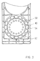
- the angular position of the display plate 38 relative to the fixing piece 40 can be freely selected via angle assignment elements 50 which, as can be seen more clearly from FIG. 3, are arranged in a 22.5 ° grid and can engage, for example, with corresponding pins of the display plate 36.
- the Bowden cable linkage 46 can be attached in any angular orientation determined by the optimal cable routing. Nevertheless, the alignment of the actuation path, for example in the manner shown in FIG. 1, is possible by the actuator 12 - taking into account ergonomic considerations - the control knob 24, of course, being plugged onto an actuating axis 52 accordingly - possibly via a flattening which is useful for power transmission.
- the symbol field arrangement 30 is inserted between the fixing piece 40 and the display plate 38 on the circumference of the cup-shaped area of these two parts, the display plate 38 each having corresponding recesses 54 for the symbol field arrangement 30.
- the fixing piece 40 also has corresponding recesses 56 for the symbol field arrangement, and behind the recesses 56 an annular channel 58 extends, which is provided with a light carrier element 60.
- the symbol field arrangement can be illuminated uniformly.
- Light guide elements (not shown) are connected to the light carrier element 60, so that all the existing control elements 12, 14 and 16 can be illuminated with a single light source.
- the mounting plate 18 is used in the same way, the opening in the area of the missing actuator that is not required being covered by a cover or an insert.
- the fixing piece 40 is formed in one piece with the mounting plate 18. It is understood that the two-piece design known from the generic document, in which the fixing piece extends on the back of the mounting plate, can also be used.
- the same parts are used as in the area of the actuator 12 described in detail.
- the parts are provided with corresponding reference numbers in FIG. 2, the reference number in question being increased by 100 compared to that in the area of the actuator 12.
- the light can be supplied, for example, in one Area 62.
- the actuator 14 is not implemented.
- the associated area of the mounting plate 18 is modified in a certain way for this purpose.
- an insert is used in the mold, which prevents the formation of the shaped piece required for the actuator 14 according to FIG. 1 in a material-saving and cost-effective manner.
- angle assignment elements 50 are provided as openings on the display plate, into which short pins of the fixing piece 40 can engage, an additional latching of the actuator 12 can be realized via a spring-loaded ball which can then snap into the angle assignment elements 50 accordingly.
Landscapes
- Engineering & Computer Science (AREA)
- Mechanical Engineering (AREA)
- Physics & Mathematics (AREA)
- Thermal Sciences (AREA)
- Power Engineering (AREA)
- Chemical & Material Sciences (AREA)
- Combustion & Propulsion (AREA)
- Transportation (AREA)
- Fluid-Damping Devices (AREA)
- Reciprocating, Oscillating Or Vibrating Motors (AREA)
- Illuminated Signs And Luminous Advertising (AREA)
- Air-Conditioning For Vehicles (AREA)
Applications Claiming Priority (2)
| Application Number | Priority Date | Filing Date | Title |
|---|---|---|---|
| DE9300295U DE9300295U1 (de) | 1993-01-12 | 1993-01-12 | Anordnung von Stellorganen |
| DE9300295U | 1993-01-12 |
Publications (2)
| Publication Number | Publication Date |
|---|---|
| EP0606862A1 true EP0606862A1 (fr) | 1994-07-20 |
| EP0606862B1 EP0606862B1 (fr) | 1996-08-21 |
Family
ID=6888029
Family Applications (1)
| Application Number | Title | Priority Date | Filing Date |
|---|---|---|---|
| EP94100216A Expired - Lifetime EP0606862B1 (fr) | 1993-01-12 | 1994-01-08 | Disposition d'organes d'actionnement |
Country Status (5)
| Country | Link |
|---|---|
| EP (1) | EP0606862B1 (fr) |
| AT (1) | ATE141549T1 (fr) |
| DE (2) | DE9300295U1 (fr) |
| HR (1) | HRP940021B1 (fr) |
| SI (1) | SI9400009A (fr) |
Families Citing this family (5)
| Publication number | Priority date | Publication date | Assignee | Title |
|---|---|---|---|---|
| DE29505606U1 (de) * | 1995-03-31 | 1996-02-01 | Siemens AG, 80333 München | Bediengerät für eine Kraftfahrzeug-Klimaautomatik |
| DE19947406C1 (de) * | 1999-10-01 | 2001-02-08 | Bayerische Motoren Werke Ag | Einstelleinrichtung |
| US6744374B1 (en) | 2000-10-02 | 2004-06-01 | Bayerische Motoren Werke Aktiengesellschaft | Setting device with rotating actuator and illuminated index display |
| DE102004052465A1 (de) * | 2004-10-28 | 2006-05-04 | Behr Gmbh & Co. Kg | Bedieneinrichtung |
| DE102013205884A1 (de) * | 2013-04-03 | 2014-10-09 | Mahle International Gmbh | Baukastensystem eines Bediengerätes |
Citations (5)
| Publication number | Priority date | Publication date | Assignee | Title |
|---|---|---|---|---|
| DE2741492A1 (de) * | 1977-09-15 | 1979-03-29 | Miele & Cie | Anzeigeeinrichtung fuer elektrische haushaltsgeraete |
| EP0129662A2 (fr) * | 1983-05-17 | 1985-01-02 | Preh-Werke GmbH & Co. KG | Dispositif indicateur par bande luminescente |
| DE3332984A1 (de) * | 1983-09-13 | 1985-03-28 | Aurora Konrad G. Schulz Gmbh & Co, 6933 Mudau | Anordnung von stellorganen, insbesondere fuer vorrichtungen zur beheizung und belueftung von fahrerkabinen, fahrgastraeumen od.dgl. in nutzfahrzeugen |
| EP0170155A1 (fr) * | 1984-08-01 | 1986-02-05 | PREH, Elektrofeinmechanische Werke Jakob Preh Nachf. GmbH & Co. | Unité de commande |
| US4930048A (en) * | 1987-09-26 | 1990-05-29 | Toyoda Gosei Co., Ltd. | Air-conditioning control box |
-
1993
- 1993-01-12 DE DE9300295U patent/DE9300295U1/de not_active Expired - Lifetime
-
1994
- 1994-01-08 AT AT94100216T patent/ATE141549T1/de not_active IP Right Cessation
- 1994-01-08 EP EP94100216A patent/EP0606862B1/fr not_active Expired - Lifetime
- 1994-01-08 DE DE59400501T patent/DE59400501D1/de not_active Expired - Fee Related
- 1994-01-11 HR HRG9300295.5A patent/HRP940021B1/xx not_active IP Right Cessation
- 1994-01-12 SI SI9400009A patent/SI9400009A/sl unknown
Patent Citations (5)
| Publication number | Priority date | Publication date | Assignee | Title |
|---|---|---|---|---|
| DE2741492A1 (de) * | 1977-09-15 | 1979-03-29 | Miele & Cie | Anzeigeeinrichtung fuer elektrische haushaltsgeraete |
| EP0129662A2 (fr) * | 1983-05-17 | 1985-01-02 | Preh-Werke GmbH & Co. KG | Dispositif indicateur par bande luminescente |
| DE3332984A1 (de) * | 1983-09-13 | 1985-03-28 | Aurora Konrad G. Schulz Gmbh & Co, 6933 Mudau | Anordnung von stellorganen, insbesondere fuer vorrichtungen zur beheizung und belueftung von fahrerkabinen, fahrgastraeumen od.dgl. in nutzfahrzeugen |
| EP0170155A1 (fr) * | 1984-08-01 | 1986-02-05 | PREH, Elektrofeinmechanische Werke Jakob Preh Nachf. GmbH & Co. | Unité de commande |
| US4930048A (en) * | 1987-09-26 | 1990-05-29 | Toyoda Gosei Co., Ltd. | Air-conditioning control box |
Also Published As
| Publication number | Publication date |
|---|---|
| DE59400501D1 (de) | 1996-09-26 |
| HRP940021A2 (en) | 1996-06-30 |
| DE9300295U1 (de) | 1993-04-29 |
| ATE141549T1 (de) | 1996-09-15 |
| EP0606862B1 (fr) | 1996-08-21 |
| HRP940021B1 (en) | 1998-06-30 |
| SI9400009A (en) | 1994-09-30 |
Similar Documents
| Publication | Publication Date | Title |
|---|---|---|
| DE19910774C2 (de) | Fahrzeug-Frischluftdüseneinrichtung | |
| EP0170107B1 (fr) | Unité de commande | |
| DE19738656C2 (de) | Fahrzeugtür | |
| EP1662207B1 (fr) | Dispositiv de contrôle pour un appareil ménager | |
| DE69707755T2 (de) | Temperatursteuerung für Fahrzeuge | |
| DE60303637T2 (de) | Schalter mit beleuchtetem Knopf | |
| DE102011112944B4 (de) | Bedienvorrichtung für ein Kraftfahrzeug | |
| EP1075979A2 (fr) | Procédé pour la mise en oeuvre d'un dispositif de commande multifonctions d'automobile et dispositif de commande multifonctions | |
| DE4011085A1 (de) | Beluefter | |
| DE4214178C1 (fr) | ||
| EP0606862B1 (fr) | Disposition d'organes d'actionnement | |
| DE69308401T2 (de) | Bedienungstafel mit Berührungstasten für die Regelung einer Klimatisiereinrichtung eines Fahrzeuginnenraums | |
| EP2981429B1 (fr) | Système modulaire d'appareil de commande | |
| DE10138118C2 (de) | Bedienelementesystem für ein Fahrzeug | |
| EP0803388B1 (fr) | Unité de commande pour une installation de chauffage pour véhicule | |
| DE102005014198B3 (de) | Bedienelement zur Einstellung einer Heiz-, Lüftungs- oder Klimaeinrichtung eines Kraftfahrzeugs | |
| DE19816013B4 (de) | Luftstromverteiler für einen Kraftfahrzeuginnenraum | |
| DE69808680T2 (de) | Steuertafel für ein Armaturenbrette ines Kraftfahrzeuges | |
| EP0884204B1 (fr) | Dispositif de commande | |
| EP0927656A2 (fr) | Panneau de commande mobile pour automobile | |
| EP0726179A1 (fr) | Appareil de commande pour une installation de chauffage ou de climatisation | |
| EP1652701B1 (fr) | Dispositif de commande | |
| DE102018119944B4 (de) | Luftausströmer mit einer Bedieneinrichtung | |
| DE4118042C2 (fr) | ||
| DE3546625C2 (en) | Electrical rotary switch having illumination |
Legal Events
| Date | Code | Title | Description |
|---|---|---|---|
| PUAI | Public reference made under article 153(3) epc to a published international application that has entered the european phase |
Free format text: ORIGINAL CODE: 0009012 |
|
| AK | Designated contracting states |
Kind code of ref document: A1 Designated state(s): AT DE FR GB IT PT |
|
| 17P | Request for examination filed |
Effective date: 19940705 |
|
| 17Q | First examination report despatched |
Effective date: 19951117 |
|
| GRAH | Despatch of communication of intention to grant a patent |
Free format text: ORIGINAL CODE: EPIDOS IGRA |
|
| GRAH | Despatch of communication of intention to grant a patent |
Free format text: ORIGINAL CODE: EPIDOS IGRA |
|
| GRAA | (expected) grant |
Free format text: ORIGINAL CODE: 0009210 |
|
| AK | Designated contracting states |
Kind code of ref document: B1 Designated state(s): AT DE FR GB IT PT |
|
| REF | Corresponds to: |
Ref document number: 141549 Country of ref document: AT Date of ref document: 19960915 Kind code of ref document: T |
|
| REF | Corresponds to: |
Ref document number: 59400501 Country of ref document: DE Date of ref document: 19960926 |
|
| ET | Fr: translation filed | ||
| ITF | It: translation for a ep patent filed | ||
| GBT | Gb: translation of ep patent filed (gb section 77(6)(a)/1977) |
Effective date: 19961127 |
|
| SC4A | Pt: translation is available |
Free format text: 961009 AVAILABILITY OF NATIONAL TRANSLATION |
|
| PLBE | No opposition filed within time limit |
Free format text: ORIGINAL CODE: 0009261 |
|
| STAA | Information on the status of an ep patent application or granted ep patent |
Free format text: STATUS: NO OPPOSITION FILED WITHIN TIME LIMIT |
|
| 26N | No opposition filed | ||
| REG | Reference to a national code |
Ref country code: GB Ref legal event code: IF02 |
|
| PGFP | Annual fee paid to national office [announced via postgrant information from national office to epo] |
Ref country code: DE Payment date: 20021026 Year of fee payment: 10 |
|
| PGFP | Annual fee paid to national office [announced via postgrant information from national office to epo] |
Ref country code: PT Payment date: 20021028 Year of fee payment: 10 |
|
| PGFP | Annual fee paid to national office [announced via postgrant information from national office to epo] |
Ref country code: FR Payment date: 20021029 Year of fee payment: 10 |
|
| PGFP | Annual fee paid to national office [announced via postgrant information from national office to epo] |
Ref country code: AT Payment date: 20021101 Year of fee payment: 10 |
|
| PGFP | Annual fee paid to national office [announced via postgrant information from national office to epo] |
Ref country code: GB Payment date: 20030103 Year of fee payment: 10 |
|
| PG25 | Lapsed in a contracting state [announced via postgrant information from national office to epo] |
Ref country code: GB Free format text: LAPSE BECAUSE OF NON-PAYMENT OF DUE FEES Effective date: 20040108 Ref country code: AT Free format text: LAPSE BECAUSE OF NON-PAYMENT OF DUE FEES Effective date: 20040108 |
|
| PG25 | Lapsed in a contracting state [announced via postgrant information from national office to epo] |
Ref country code: PT Free format text: LAPSE BECAUSE OF NON-PAYMENT OF DUE FEES Effective date: 20040731 |
|
| PG25 | Lapsed in a contracting state [announced via postgrant information from national office to epo] |
Ref country code: DE Free format text: LAPSE BECAUSE OF NON-PAYMENT OF DUE FEES Effective date: 20040803 |
|
| GBPC | Gb: european patent ceased through non-payment of renewal fee |
Effective date: 20040108 |
|
| PG25 | Lapsed in a contracting state [announced via postgrant information from national office to epo] |
Ref country code: FR Free format text: LAPSE BECAUSE OF NON-PAYMENT OF DUE FEES Effective date: 20040930 |
|
| REG | Reference to a national code |
Ref country code: FR Ref legal event code: ST |
|
| PG25 | Lapsed in a contracting state [announced via postgrant information from national office to epo] |
Ref country code: IT Free format text: LAPSE BECAUSE OF NON-PAYMENT OF DUE FEES Effective date: 20050108 |