EP0606850B1 - Akkumulator mit die Pole verdeckender lösbarer Abdeckplatte - Google Patents
Akkumulator mit die Pole verdeckender lösbarer Abdeckplatte Download PDFInfo
- Publication number
- EP0606850B1 EP0606850B1 EP94100126A EP94100126A EP0606850B1 EP 0606850 B1 EP0606850 B1 EP 0606850B1 EP 94100126 A EP94100126 A EP 94100126A EP 94100126 A EP94100126 A EP 94100126A EP 0606850 B1 EP0606850 B1 EP 0606850B1
- Authority
- EP
- European Patent Office
- Prior art keywords
- cover
- latch
- accumulator
- recess
- accordance
- Prior art date
- Legal status (The legal status is an assumption and is not a legal conclusion. Google has not performed a legal analysis and makes no representation as to the accuracy of the status listed.)
- Expired - Lifetime
Links
- 239000002184 metal Substances 0.000 claims abstract description 5
- 230000000295 complement effect Effects 0.000 claims description 3
- 238000003466 welding Methods 0.000 claims description 2
- 230000015572 biosynthetic process Effects 0.000 claims 1
- 238000009434 installation Methods 0.000 description 2
- 238000005267 amalgamation Methods 0.000 description 1
- 238000011161 development Methods 0.000 description 1
- 230000018109 developmental process Effects 0.000 description 1
- 230000000694 effects Effects 0.000 description 1
- 230000001771 impaired effect Effects 0.000 description 1
- 230000014759 maintenance of location Effects 0.000 description 1
Images

Classifications
-
- H—ELECTRICITY
- H01—ELECTRIC ELEMENTS
- H01R—ELECTRICALLY-CONDUCTIVE CONNECTIONS; STRUCTURAL ASSOCIATIONS OF A PLURALITY OF MUTUALLY-INSULATED ELECTRICAL CONNECTING ELEMENTS; COUPLING DEVICES; CURRENT COLLECTORS
- H01R11/00—Individual connecting elements providing two or more spaced connecting locations for conductive members which are, or may be, thereby interconnected, e.g. end pieces for wires or cables supported by the wire or cable and having means for facilitating electrical connection to some other wire, terminal, or conductive member, blocks of binding posts
- H01R11/11—End pieces or tapping pieces for wires, supported by the wire and for facilitating electrical connection to some other wire, terminal or conductive member
- H01R11/28—End pieces consisting of a ferrule or sleeve
- H01R11/281—End pieces consisting of a ferrule or sleeve for connections to batteries
- H01R11/284—End pieces consisting of a ferrule or sleeve for connections to batteries comprising means for preventing corrosion, e.g. covers, enclosures filled with gel
-
- Y—GENERAL TAGGING OF NEW TECHNOLOGICAL DEVELOPMENTS; GENERAL TAGGING OF CROSS-SECTIONAL TECHNOLOGIES SPANNING OVER SEVERAL SECTIONS OF THE IPC; TECHNICAL SUBJECTS COVERED BY FORMER USPC CROSS-REFERENCE ART COLLECTIONS [XRACs] AND DIGESTS
- Y02—TECHNOLOGIES OR APPLICATIONS FOR MITIGATION OR ADAPTATION AGAINST CLIMATE CHANGE
- Y02E—REDUCTION OF GREENHOUSE GAS [GHG] EMISSIONS, RELATED TO ENERGY GENERATION, TRANSMISSION OR DISTRIBUTION
- Y02E60/00—Enabling technologies; Technologies with a potential or indirect contribution to GHG emissions mitigation
- Y02E60/10—Energy storage using batteries
Definitions
- the invention relates to an accumulator with at least a metal pole arranged in a corner region of the cover according to the preamble of claim 1.
- End pole covers of conventional design are by means of a snap hook attached, under the bottom of one on the lid provided circumferential lid apron. With too little Undercut between the apron and the one below The battery housing is the holder of the end pole cap insufficient.
- a disadvantage of the known accumulator is further that by reaching over the snap hook the outer dimensions over the outer circumference of the lid apron the battery can be changed, what with tight Installation conditions, such as the amalgamation of several individual accumulators for battery blocks the release of the snap hook difficult.
- it turns out with the known end pole caps as a disadvantage that with frequently changing Installation situations of the cable connector of the snap hook in the Way stands. The feed is for the same reason several of the generally very thick cables into one the known cover cap covered pole problematic, if not impossible.
- the aim of the invention is an accumulator to create the type mentioned, its pole cap neither the outside dimensions of the battery not changed and in particular the universal connection of cables allows without the quality of the bracket of Cover cap on the lid of the battery and its manipulability be affected.
- the idea of the invention is therefore to be seen in the fact that the Locking means are located above the bottom surface of the recess, so that the part of the lid underneath, in particular the cover apron for fastening the cover plate is not needed. It is particularly advantageous that the lateral dimensions of the battery through the Cover cap are not affected.
- cover plates according to claim 3 in held sideways. In this case it is Arrangement of the latching projection which effects the holder upwards advantageous according to claim 7.
- a first practical embodiment is by Claims 8, 9 marked.
- a particularly good retention of the cover cap is also by the embodiment according to claims 10, 11 achieved.
- the invention is particularly advantageous for one Accumulator according to claim 16 applied because of the measures according to the invention the distance of the lid surface from the bottom of the lid apron no longer critical is.
- the invention thus creates an end pole cover cap attachment, the only above the circumferential lid apron is arranged, whereby the prescribed dimensions of the accumulator are not impaired and loosening of the cover plate even in tight spaces is possible.
- cables from both sides of the corner and from the corner itself without any problems be led to the pole. It can also be done easily several cables are brought up to the pole without this is hindered by the cover plate.
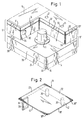
- FIG. 1 shows a partially shown Accumulator housing 24 has a lid 13 on it Bottom with an all-round and laterally over the Housing 24 projecting lid apron 33 is provided. Above the cover apron 33, the cover 13 jumps at 38 back a bit and then forms vertical Side walls, of which only the up to corners 35, 39 in FIG. 1 extending end parts 31, 32 are shown.
- the cover In the area of a corner 19 of the lid apron 33 or 40 of the Housing 24, the cover has a recess 12 rectangular or square horizontal cross section, whose bottom surface 14 with the upper surface 38 of the Lid apron 33 is flush.
- the recess 12 is open to the outside and inwards through side walls arranged at right angles to one another and vertically 16, 17 limited and below by a bottom surface 14 completed.
- Edge strip 23 of the cover plate 18 comes when placing the same on the lid 13 on a narrow strip of Lid surface 15 immediately adjacent to the top of the Side wall 16 for support.
- a projection designed as a spring bar 34 which is designed in the manner of a leaf spring, the Level runs parallel to the level of the side wall 16. in the lower region of the projection 34 is a to the side wall 16 extending locking projection 29 is provided, the when the cover plate 18 is placed on the cover 13 Fig. 1 in a provided in the side wall 16 complementary Snap recess 30 can snap.
- the lid 13 of FIG. 1 is made by a horizontal one Welding plane 37 separate cover parts 13 ', 13 '' welded together.
- the cover plate 18 is assembled as follows: After the cable connectors (not shown) are attached to the pole 11, the retaining pins 20 are first inserted into the associated holes 21, it being possible for the part 18 ′ of the cover plate 18 that bears the projection 34 to be folded up a little around the hinge 42. As soon as the part 18 ′′ with the edge strip 22 completely rests on the cover surface 15, the part 18 ′ of the cover plate 18 that bears the projection 34 is folded down, the projection 34 initially sliding somewhat away from the side wall 16 when the latching projection 29 slides along Side wall 16 is resiliently bent away until finally the locking projection 29 snaps into the locking recess 30, whereupon the cover plate 18 is finally fixed.
- the ball-shaped design of the locking projection 29 and the locking recess 30 ensure that a disengagement by lifting the cover plate 18 is possible.
- connection between the cable and the pole 11 can removed cover plate 18 or even with only folded up Part 18 'are made.
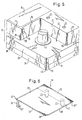
- the projection 34 ' is again formed like a leaf spring, but the Plane of the projection 34 ′ parallel to the side wall end part 31 or perpendicular to the side wall 16, so that the Locking projection 25, which with a 35 in the corner provided recess 26 works together from the Side wall 31 is resiliently bendable.
- Locking projection 29 and the projection 34 'completely in the Area of the recess 12 are housed at 3 and 4 of the projection 34 ' by its relatively small thickness over the side wall 31.
- the thickness of the projection 34 ' is so small that that a side protrusion over the lid apron 33 is avoided.
- the locking projection 25 and the locking recess 26 easily formed as deep be that a secure locking connection is created.
- the Locking recess 28 can also be realized in that the side wall part 31 in the upper region into the depression 12 is extended into it, whereby there is a latching web 36, below which the locking recess 28 is formed.
- a locking projection 27 which is like a leaf spring trained projection 34 'is provided which is similar to that in FIG. 4, that is to say from the side wall end part 31 is designed to be resilient.
- the Locking web 36 but also undercut by a projection be on a spring bar 34, as shown in Fig. 2nd is shown, is formed.
- the projection 34 'and the locking projection 27 are according to FIG. 6 so narrow that a correspondence with the width the locking recess 28 is given. Opposite that on the Cover surface 15 overlying edge strips 23 are the Projection 34 'and the locking projection 27 slightly to the corner 18' '' moved there. In this way, the edge strip on the one hand 23 rest securely on the lid surface 15 and at the same time the spring bar 34 'with the locking projection 27 work properly with the recess 28.
- the by the offset of the projection 34 'with respect to the edge strip 23 formed stage is designated 43.
Landscapes
- Details Of Indoor Wiring (AREA)
- Battery Mounting, Suspending (AREA)
- Connection Of Batteries Or Terminals (AREA)
- Electromechanical Clocks (AREA)
- Telephone Set Structure (AREA)
- Road Signs Or Road Markings (AREA)
- Professional, Industrial, Or Sporting Protective Garments (AREA)
- Sealing Battery Cases Or Jackets (AREA)
- Air Bags (AREA)
Description
- Fig. 1
- eine perspektivische Schrägdraufsicht auf einen erfindungsgemäß ausgebildeten Eckbereich eines Akkumulators bei abgenommener Abdeckplatte,
- Fig. 1
- eine entsprechende perspektivische Ansicht der für die Ausführungsform nach Fig. 1 bestimmten Abdeckplatte,
- Fig. 3
- eine zu Fig. 1 analoge perspektivische Schrägdraufsicht einer weiteren Ausführungsform bei abgenommener Abdeckplatte,
- Fig. 4
- eine entsprechende perspektivische Schrägdraufsicht der Abdeckplatte für die Ausführungsform nach Fig.3,
- Fig. 5
- eine zu den Fig. 1 und 3 analoge perspektivische Schrägdraufsicht einer weiteren Ausführungsform bei abgenommener Abdeckplatte und
- Fig. 6
- eine perspektivische Schrägdraufsicht der Abdeckplatte für die Ausführungsform nach Fig. 5.
Nachdem die nicht dargestellten Kabelverbinder am Pol 11 angebracht sind, werden zunächst die Haltestifte 20 in die zugeordneten Löcher 21 eingesteckt, wobei der den Vorsprung 34 tragende Teil 18' der Abdeckplatte 18 um das Scharnier 42 etwas hochgeklappt sein kann. Sobald der Teil 18'' mit dem Randstreifen 22 vollständig auf der Deckeloberfläche 15 aufliegt, wird der den Vorsprung 34 tragende Teil 18' der Abdeckplatte 18 nach unten geklappt, wobei der Vorsprung 34 beim Entlanggleiten des Rastvorsprunges 29 an der Seitenwand 16 zunächst etwas von der Seitenwand 16 federnd weggebogen wird, bis schließlich der Rastvorsprung 29 in die Rastvertiefung 30 einschnappt, worauf die Abdeckplatte 18 endgültig festgelegt ist. Die kugelkuppenartige Ausbildung des Rastvorsprunges 29 und der Rastvertiefung 30 sorgen dafür, daß auch ein Ausrasten durch Hochheben der Abdeckplatte 18 möglich ist.
Claims (20)
- Akkumulator mit wenigstens einem in einem Eckbereich seines Deckels (13) vorgesehenen Metallpol (11), der in einer vorzugsweise rechteckigen, insbesondere quadratischen Vertiefung (12), die nach innen durch insbesondere senkrecht zur Deckeloberfläche (15) verlaufende Wände (16, 17) begrenzt und nach außen offen ist und von deren vorzugsweise ebener Bodenfläche (14) der Metallpol (11) bis höchstens zur Deckeloberfläche (15) nach oben vorsteht, wobei die Vertiefung (12) oben durch eine mit zwei ineinander übergehenden Randstreifen (22, 23) auf der Deckeloberfläche (15) aufliegende, bevorzugt im wesentlichen rechteckige oder quadratische Abdeckplatte (18) abgedeckt ist, die durch sie gegen Bewegungen parallel zur Bodenfläche (14) fixierende Seitenhaltemittel (20, 21), vorzugsweise durch Stift(20)-Loch(21)-Verbindungen zwischen der unteren Fläche wenigstens eines der Randstreifen (22, 23) und dem Deckel (13) und vorzugsweise wenigstens einen sich nach unten erstreckenden Vorsprung (34, 34') an der Abdeckplatte (18) umfassende, sie gegen Bewegungen nach oben haltende Rastmittel (25, 26; 27, 28; 29, 30) lösbar am Deckel (13) gehalten ist und wenigstens auf einer Seite der Ecke (19) und im Bereich der Ecke (19) zwischen ihrer unteren Fläche und der Bodenfläche (14) eine Durchtrittsöffnung für ein an den Pol (11) anzuschließendes Kabel beläßt,
dadurch gekennzeichnet,
daß die Abdeckplatte (18) keine sich über die Außenkontur des Gehäuses (40) und/oder des Deckels (13) einschließlich einer etwaigen rundumlaufenden Deckelschürze (33) erstreckenden Teile aufweist und die Rastmittel (25, 26; 27, 28; 29, 30) im Bereich zwischen der Bodenfläche (14) und der Deckeloberfläche (15) vorgesehen sind. - Akkumulator nach Anspruch 1,
dadurch gekennzeichnet,
daß die Rastmittel (25, 26; 27, 28; 29, 30) nur im Bereich der Seitenwände (16, 17) der Vertiefung (12) vorgesehen sind. - Akkumulator nach Anspruch 1 oder 2,
dadurch gekennzeichnet,
daß die Rastmittel (25, 26; 27, 28; 29, 30) oberhalb der Bodenfläche (14) zwischen dem sich von der Abdeckplatte (18) nach unten erstreckenden Vorsprung (34, 34') und den Seitenwänden (16, 17) der Vertiefung (12) vorgesehen sind. - Akkumulator nach einem der vorhergehenden Ansprüche,
dadurch gekennzeichnet,
daß die Rastmittel eine Rastvertiefung (26, 28, 30) aufweisen, die oberhalb der Bodenfläche (14) in den Seitenwänden (16, 17) der Vertiefung (12) und/oder den in gleicher Höhe liegenden, diesen unmittelbar benachbarten Teilen (31, 32) der Seitenwände des Deckels (13) ausgebildet sind, und der Vorsprung (34, 34') der Abdeckplatte (18) einen mit der Rastvertiefung (26, 28, 30) zusammenarbeitenden Rastvorsprung (27, 29, 30) trägt und sich nach unten höchstens bis zur Bodenfläche 14 der Vertiefung (12) erstreckt. - Akkumulator nach Anspruch 4,
dadurch gekennzeichnet,
daß sich die Rastvorsprünge (25, 27, 29) seitlich nicht über die Außenkontur des Deckels (13), insbesondere einer nach unten an ihm vorgesehenen Deckelschürze (33) und des Gehäuses (40) hinauserstrecken. - Akkumulator nach einem der vorhergehenden Ansprüche,
dadurch gekennzeichnet,
daß die Abdeckplatte (18) an ihrem einen auf der Deckeloberfläche aufliegenden Randstreifen (22) wenigstens einen und vorzugsweise zwei sich nach unten in dazu komplementäre Bohrungen (21) des Deckels (25) erstreckende Haltestifte (20) trägt. - Akkumulator nach Anspruch 6,
dadurch gekennzeichnet,
daß der die Rastvorsprünge (25, 27, 29) tragende Vorsprung (34, 34') an oder nahe dem anderen Rand (23) angeordnet ist. - Akkumulator nach einem der vorhergehenden Ansprüche,
dadurch gekennzeichnet,
daß in einer (16) der Seitenwände (16, 17) der Vertiefung (12) eine Rastvertiefung (30) vorgesehen ist, in die ein an dem sich von einem randnahen Bereich der Abdeckplatte (18) nach unten erstreckenden, als senkrecht von der Seitenwand (16) federnd wegbiegbarer Federsteg ausgebildeten Vorsprung (34) vorgesehener Rastvorsprung (29) lösbar eingreift. - Akkumulator nach Anspruch 8,
dadurch gekennzeichnet,
daß die Rastvertiefung (30) nahe der Ecke (35) angeordnet ist, wo die Seitenwand (16) der Vertiefung (12) in die Seitenwand (31) des Deckels (15) übergeht. - Akkumulator nach einem der Ansprüche 1 bis 7,
dadurch gekennzeichnet,
daß im Bereich der Ecke (35) zwischen einer der Seitenwände (16) der Vertiefung (12) und der angrenzenden Seitenwand (31) des Deckels (15) eine Rastvertiefung (26) vorgesehen ist, in die ein an dem sich von der Abdeckplatte (18) nach unten erstreckenden, als Federsteg ausgebildeten Vorsprung (34') vorgesehener Rastvorsprung (25) eingreift. - Akkumulator nach Anspruch 10,
dadurch gekennzeichnet,
daß der Vorsprung (34') in Richtung von einer der Seitenwände (16, 31) oder der Ecke (35) weg federnd biegbar ist, um den Rastvorsprung (25) und die Rastvertiefung (26) außer Eingriff bringen zu können. - Akkumultor nach einem der Ansprüche 1 bis 7,
dadurch gekennzeichnet,
daß zur Bildung einer Rastvertiefung (28) von einer der Seitenwände (16, 17) der Vertiefung (12) ein Raststeg (36) in solchem Abstand von der Bodenfläche (14) der Vertiefung (12) vorspringt, daß darunter die Rastvertiefung (28) ausgebildet ist. - Akkumulator nach Anspruch 12,
dadurch gekennzeichnet,
daß der Raststeg (36) sich im oberen Bereich der zugeordneten Seitenwand (16, 17) befindet. - Akkumulator nach Anspruch 12 oder 13,
dadurch gekennzeichnet,
daß der Raststeg (36) an der Ecke (35) zum benachbarten Teil (31) der Seitenwand des Deckels (13) vorgesehen ist. - Akkumulator nach Anspruch 14,
dadurch gekennzeichnet,
daß der Raststeg (36) als Verlängerung des oberen Teils der benachbarten Seitenwand (31) des Deckels (15) ausgebildet ist. - Akkumulator nach einem der vorhergehenden Ansprüche,
dadurch gekennzeichnet,
daß der Deckel (13) aus zwei durch eine horizontale Schweißebene (37) voneinander getrennten Deckelteilen (13', 13'') besteht. - Akkumulator nach einem der vorhergehenden Ansprüche,
dadurch gekennzeichnet,
daß parallel zu dem durch die Seitenhaltemittel (21, 22), insbesondere die Haltestifte (20) und Bohrungen (21) am Deckel (13) gehaltenen Randstreifen (22) die Abdeckplatte (18) ein Scharnier (42) aufweist, um das der den Rastvorsprung (25, 27, 29) tragende Teil (18') der Abdeckplatte (18) nach oben bzw. unten klappbar ist, wobei die Rastmittel (25, 26; 27, 28; 29, 30) so ausgebildet sind, daß sie durch Herumklappen des sie tragenden Teils (18') um das Scharnier (42) in und außer Eingriff miteinander bringbar sind. - Akkumulator nach Anspruch 17,
dadurch gekennzeichnet,
daß das Scharnier (42) sich im Bereich des oberen Randes der zugeordneten Seitenwand (17) befindet. - Akkumulator nach Anspruch 17 oder 18,
dadurch gekennzeichnet,
daß das Scharnier (42) durch eine vorzugsweise in der unteren Fläche der Abdeckplatte (18) vorgesehene Rille realisiert ist. - Akkumulator nach einem der vorhergehenden Ansprüche,
dadurch gekennzeichnet,
daß die Ränder der Abdeckplatte (18) mit den oberen Rändern der Seitenwände (31, 32) des Deckels (15) fluchten und/oder ihre mit der Ecke (19, 40) des Deckels (13) bzw. des Gehäuses (24) fluchtende Ecke (18''') abgerundet ist.
Applications Claiming Priority (2)
| Application Number | Priority Date | Filing Date | Title |
|---|---|---|---|
| DE4300567A DE4300567A1 (de) | 1993-01-12 | 1993-01-12 | Akkumulator mit die Pole verdeckender lösbarer Abdeckplatte |
| DE4300567 | 1993-01-12 |
Publications (3)
| Publication Number | Publication Date |
|---|---|
| EP0606850A2 EP0606850A2 (de) | 1994-07-20 |
| EP0606850A3 EP0606850A3 (en) | 1997-01-29 |
| EP0606850B1 true EP0606850B1 (de) | 2000-09-20 |
Family
ID=6478018
Family Applications (1)
| Application Number | Title | Priority Date | Filing Date |
|---|---|---|---|
| EP94100126A Expired - Lifetime EP0606850B1 (de) | 1993-01-12 | 1994-01-05 | Akkumulator mit die Pole verdeckender lösbarer Abdeckplatte |
Country Status (4)
| Country | Link |
|---|---|
| EP (1) | EP0606850B1 (de) |
| AT (1) | ATE196563T1 (de) |
| DE (2) | DE4300567A1 (de) |
| ES (1) | ES2149826T3 (de) |
Families Citing this family (4)
| Publication number | Priority date | Publication date | Assignee | Title |
|---|---|---|---|---|
| KR101689750B1 (ko) * | 2014-01-21 | 2016-12-26 | 주식회사 엘지화학 | 배터리 팩 |
| KR102065106B1 (ko) * | 2015-12-18 | 2020-01-10 | 주식회사 엘지화학 | 이차전지 팩 |
| KR102061293B1 (ko) * | 2015-12-23 | 2019-12-31 | 주식회사 엘지화학 | 이차전지 팩 |
| CN113614992A (zh) * | 2019-02-08 | 2021-11-05 | Cps 科技控股有限公司 | 端子盖 |
Family Cites Families (5)
| Publication number | Priority date | Publication date | Assignee | Title |
|---|---|---|---|---|
| US3937636A (en) * | 1975-06-12 | 1976-02-10 | Eltra Corporation | Battery with recessed terminals and fuse |
| GB1548129A (en) * | 1978-02-17 | 1979-07-04 | Chloride Group Ltd | Electric storage battery lids |
| DE7826754U1 (de) * | 1978-09-08 | 1980-05-08 | Accumulatorenfabrik Sonnenschein Gmbh, 6470 Buedingen | Vorrichtung zum abdecken der vom deckel eines akkumulators nach oben abstehenden anschlusspole |
| DE3333308C2 (de) * | 1983-09-15 | 1986-06-05 | Ford-Werke AG, 5000 Köln | Leiteranschluß für Starterbatterien, insbesondere von Kraftfahrzeugen |
| DE3729523A1 (de) * | 1987-09-03 | 1989-03-16 | Varta Batterie | Akkumulatorenbatterie |
-
1993
- 1993-01-12 DE DE4300567A patent/DE4300567A1/de not_active Withdrawn
-
1994
- 1994-01-05 AT AT94100126T patent/ATE196563T1/de not_active IP Right Cessation
- 1994-01-05 EP EP94100126A patent/EP0606850B1/de not_active Expired - Lifetime
- 1994-01-05 ES ES94100126T patent/ES2149826T3/es not_active Expired - Lifetime
- 1994-01-05 DE DE59409524T patent/DE59409524D1/de not_active Expired - Fee Related
Also Published As
| Publication number | Publication date |
|---|---|
| ES2149826T3 (es) | 2000-11-16 |
| DE59409524D1 (de) | 2000-10-26 |
| EP0606850A2 (de) | 1994-07-20 |
| ATE196563T1 (de) | 2000-10-15 |
| EP0606850A3 (en) | 1997-01-29 |
| DE4300567A1 (de) | 1994-07-14 |
Similar Documents
| Publication | Publication Date | Title |
|---|---|---|
| DE60014791T2 (de) | Leicht montierbares Gehäuse für eine Datenkarte | |
| DE2656178C2 (de) | Einrichtung zum Verbinden von Pontons | |
| DE20108895U1 (de) | Kastenmodul für Gegenstände | |
| DE3902703A1 (de) | Elektrischer verbinder mit doppelverriegelung | |
| DE2911094A1 (de) | Plattenverbindungssystem | |
| DE2205011B2 (de) | Abdeckvorrichtung für die Frontfläche einer elektrischen Steckdose | |
| DE68904265T2 (de) | Transportkasten mit einem mit integriertem scharnier versehenen deckel und verfahren zu seiner herstellung. | |
| DE2729737C3 (de) | Dicht verschließbarer, unterteilbarer Behälter | |
| DE19540112B4 (de) | Gehäuse zur Installation, Isolierung und Einkapselung elektrischer, elektronischer und pneumatischer Geräte und Vorrichtungen | |
| EP0606850A2 (de) | Akkumulator mit die Pole verdeckender lösbarer Abdeckplatte | |
| DE2459635A1 (de) | Anschlussockel mit abnehmbarem deckel | |
| DE3035669A1 (de) | Geraet mit mindestens zwei mittels einesm rasthakens loesbar miteinander verbundenen teilen | |
| WO1994022183A1 (de) | Steckverbinder mit leitungsaustrittskanal | |
| DE2557697C3 (de) | Abdeckvorrichtung mit einem schwenkbaren Deckel für das Gehäuse eines Geräts | |
| DE69403048T2 (de) | Kontakthalte-Montagestruktur für Verbinder | |
| DE69321081T2 (de) | Gehäuse für ein tragbares Miniaturgerät | |
| DE68901818T2 (de) | Abgedichtetes gehaeuse, insbesondere fuer elektrische oder elektronische baugruppen. | |
| DE3145203A1 (de) | Kassette zur aufnahme von langgestreckten gegenstaenden | |
| DE2714885C3 (de) | Verdrahtungskanal | |
| EP0378065A2 (de) | Gehäuseteil mit angesetztem Stecker | |
| DE69502158T2 (de) | Verbesserungen an Geräteträger-Elementen für Kabelhalter | |
| DE9408377U1 (de) | Behälter | |
| DE4039239A1 (de) | Vielpolige elektrische steckvorrichtung | |
| DE19508150A1 (de) | Elektrische Dose, insbesondere Verbindungsdose | |
| DE8802420U1 (de) | Koffer für Werkzeuge bzw. Bauteile |
Legal Events
| Date | Code | Title | Description |
|---|---|---|---|
| PUAI | Public reference made under article 153(3) epc to a published international application that has entered the european phase |
Free format text: ORIGINAL CODE: 0009012 |
|
| AK | Designated contracting states |
Kind code of ref document: A2 Designated state(s): AT CH DE DK ES FR GB IT LI LU PT SE |
|
| PUAL | Search report despatched |
Free format text: ORIGINAL CODE: 0009013 |
|
| AK | Designated contracting states |
Kind code of ref document: A3 Designated state(s): AT CH DE DK ES FR GB IT LI LU PT SE |
|
| 17P | Request for examination filed |
Effective date: 19970716 |
|
| 17Q | First examination report despatched |
Effective date: 19980218 |
|
| GRAG | Despatch of communication of intention to grant |
Free format text: ORIGINAL CODE: EPIDOS AGRA |
|
| 17Q | First examination report despatched |
Effective date: 19980218 |
|
| GRAG | Despatch of communication of intention to grant |
Free format text: ORIGINAL CODE: EPIDOS AGRA |
|
| GRAH | Despatch of communication of intention to grant a patent |
Free format text: ORIGINAL CODE: EPIDOS IGRA |
|
| GRAH | Despatch of communication of intention to grant a patent |
Free format text: ORIGINAL CODE: EPIDOS IGRA |
|
| GRAA | (expected) grant |
Free format text: ORIGINAL CODE: 0009210 |
|
| ITF | It: translation for a ep patent filed | ||
| AK | Designated contracting states |
Kind code of ref document: B1 Designated state(s): AT CH DE DK ES FR GB IT LI LU PT SE |
|
| REF | Corresponds to: |
Ref document number: 196563 Country of ref document: AT Date of ref document: 20001015 Kind code of ref document: T |
|
| REG | Reference to a national code |
Ref country code: CH Ref legal event code: EP |
|
| GBT | Gb: translation of ep patent filed (gb section 77(6)(a)/1977) |
Effective date: 20000920 |
|
| REF | Corresponds to: |
Ref document number: 59409524 Country of ref document: DE Date of ref document: 20001026 |
|
| ET | Fr: translation filed | ||
| REG | Reference to a national code |
Ref country code: ES Ref legal event code: FG2A Ref document number: 2149826 Country of ref document: ES Kind code of ref document: T3 |
|
| PGFP | Annual fee paid to national office [announced via postgrant information from national office to epo] |
Ref country code: FR Payment date: 20001120 Year of fee payment: 8 |
|
| PGFP | Annual fee paid to national office [announced via postgrant information from national office to epo] |
Ref country code: GB Payment date: 20001127 Year of fee payment: 8 |
|
| PG25 | Lapsed in a contracting state [announced via postgrant information from national office to epo] |
Ref country code: PT Free format text: LAPSE BECAUSE OF FAILURE TO SUBMIT A TRANSLATION OF THE DESCRIPTION OR TO PAY THE FEE WITHIN THE PRESCRIBED TIME-LIMIT Effective date: 20001220 Ref country code: DK Free format text: LAPSE BECAUSE OF FAILURE TO SUBMIT A TRANSLATION OF THE DESCRIPTION OR TO PAY THE FEE WITHIN THE PRESCRIBED TIME-LIMIT Effective date: 20001220 |
|
| PG25 | Lapsed in a contracting state [announced via postgrant information from national office to epo] |
Ref country code: LU Free format text: LAPSE BECAUSE OF NON-PAYMENT OF DUE FEES Effective date: 20010105 Ref country code: AT Free format text: LAPSE BECAUSE OF NON-PAYMENT OF DUE FEES Effective date: 20010105 |
|
| PGFP | Annual fee paid to national office [announced via postgrant information from national office to epo] |
Ref country code: ES Payment date: 20010123 Year of fee payment: 8 |
|
| PGFP | Annual fee paid to national office [announced via postgrant information from national office to epo] |
Ref country code: SE Payment date: 20010130 Year of fee payment: 8 |
|
| PG25 | Lapsed in a contracting state [announced via postgrant information from national office to epo] |
Ref country code: LI Free format text: LAPSE BECAUSE OF NON-PAYMENT OF DUE FEES Effective date: 20010131 Ref country code: CH Free format text: LAPSE BECAUSE OF NON-PAYMENT OF DUE FEES Effective date: 20010131 |
|
| PGFP | Annual fee paid to national office [announced via postgrant information from national office to epo] |
Ref country code: DE Payment date: 20010228 Year of fee payment: 8 |
|
| PLBE | No opposition filed within time limit |
Free format text: ORIGINAL CODE: 0009261 |
|
| STAA | Information on the status of an ep patent application or granted ep patent |
Free format text: STATUS: NO OPPOSITION FILED WITHIN TIME LIMIT |
|
| 26N | No opposition filed | ||
| REG | Reference to a national code |
Ref country code: CH Ref legal event code: PL |
|
| REG | Reference to a national code |
Ref country code: GB Ref legal event code: IF02 |
|
| PG25 | Lapsed in a contracting state [announced via postgrant information from national office to epo] |
Ref country code: GB Free format text: LAPSE BECAUSE OF NON-PAYMENT OF DUE FEES Effective date: 20020105 |
|
| PG25 | Lapsed in a contracting state [announced via postgrant information from national office to epo] |
Ref country code: SE Free format text: LAPSE BECAUSE OF NON-PAYMENT OF DUE FEES Effective date: 20020106 |
|
| PG25 | Lapsed in a contracting state [announced via postgrant information from national office to epo] |
Ref country code: ES Free format text: LAPSE BECAUSE OF NON-PAYMENT OF DUE FEES Effective date: 20020108 |
|
| PG25 | Lapsed in a contracting state [announced via postgrant information from national office to epo] |
Ref country code: DE Free format text: LAPSE BECAUSE OF NON-PAYMENT OF DUE FEES Effective date: 20020801 |
|
| EUG | Se: european patent has lapsed |
Ref document number: 94100126.5 |
|
| GBPC | Gb: european patent ceased through non-payment of renewal fee |
Effective date: 20020105 |
|
| PG25 | Lapsed in a contracting state [announced via postgrant information from national office to epo] |
Ref country code: FR Free format text: LAPSE BECAUSE OF NON-PAYMENT OF DUE FEES Effective date: 20020930 |
|
| REG | Reference to a national code |
Ref country code: FR Ref legal event code: ST |
|
| REG | Reference to a national code |
Ref country code: ES Ref legal event code: FD2A Effective date: 20030922 |
|
| PG25 | Lapsed in a contracting state [announced via postgrant information from national office to epo] |
Ref country code: IT Free format text: LAPSE BECAUSE OF NON-PAYMENT OF DUE FEES;WARNING: LAPSES OF ITALIAN PATENTS WITH EFFECTIVE DATE BEFORE 2007 MAY HAVE OCCURRED AT ANY TIME BEFORE 2007. THE CORRECT EFFECTIVE DATE MAY BE DIFFERENT FROM THE ONE RECORDED. Effective date: 20050105 |