EP0605820B1 - Interrupteur de sécurité - Google Patents
Interrupteur de sécurité Download PDFInfo
- Publication number
- EP0605820B1 EP0605820B1 EP19930120264 EP93120264A EP0605820B1 EP 0605820 B1 EP0605820 B1 EP 0605820B1 EP 19930120264 EP19930120264 EP 19930120264 EP 93120264 A EP93120264 A EP 93120264A EP 0605820 B1 EP0605820 B1 EP 0605820B1
- Authority
- EP
- European Patent Office
- Prior art keywords
- key
- actuator
- pins
- safety switch
- switch according
- Prior art date
- Legal status (The legal status is an assumption and is not a legal conclusion. Google has not performed a legal analysis and makes no representation as to the accuracy of the status listed.)
- Expired - Lifetime
Links
- 230000037431 insertion Effects 0.000 claims description 6
- 238000003780 insertion Methods 0.000 claims description 6
- 230000036316 preload Effects 0.000 description 2
- 230000001681 protective effect Effects 0.000 description 2
- 230000006835 compression Effects 0.000 description 1
- 238000007906 compression Methods 0.000 description 1
Images

Classifications
-
- H—ELECTRICITY
- H01—ELECTRIC ELEMENTS
- H01H—ELECTRIC SWITCHES; RELAYS; SELECTORS; EMERGENCY PROTECTIVE DEVICES
- H01H27/00—Switches operated by a removable member, e.g. key, plug or plate; Switches operated by setting members according to a single predetermined combination out of several possible settings
- H01H27/002—Switches operated by a removable member, e.g. key, plug or plate; Switches operated by setting members according to a single predetermined combination out of several possible settings wherein one single insertion movement of a key comprises an unlocking stroke and a switch actuating stroke, e.g. security switch for safety guards
-
- Y—GENERAL TAGGING OF NEW TECHNOLOGICAL DEVELOPMENTS; GENERAL TAGGING OF CROSS-SECTIONAL TECHNOLOGIES SPANNING OVER SEVERAL SECTIONS OF THE IPC; TECHNICAL SUBJECTS COVERED BY FORMER USPC CROSS-REFERENCE ART COLLECTIONS [XRACs] AND DIGESTS
- Y10—TECHNICAL SUBJECTS COVERED BY FORMER USPC
- Y10T—TECHNICAL SUBJECTS COVERED BY FORMER US CLASSIFICATION
- Y10T70/00—Locks
- Y10T70/70—Operating mechanism
- Y10T70/7441—Key
- Y10T70/7486—Single key
- Y10T70/7508—Tumbler type
- Y10T70/752—Sliding tumblers
- Y10T70/7531—Transverse
-
- Y—GENERAL TAGGING OF NEW TECHNOLOGICAL DEVELOPMENTS; GENERAL TAGGING OF CROSS-SECTIONAL TECHNOLOGIES SPANNING OVER SEVERAL SECTIONS OF THE IPC; TECHNICAL SUBJECTS COVERED BY FORMER USPC CROSS-REFERENCE ART COLLECTIONS [XRACs] AND DIGESTS
- Y10—TECHNICAL SUBJECTS COVERED BY FORMER USPC
- Y10T—TECHNICAL SUBJECTS COVERED BY FORMER US CLASSIFICATION
- Y10T70/00—Locks
- Y10T70/70—Operating mechanism
- Y10T70/7441—Key
- Y10T70/7751—With ball or roller
-
- Y—GENERAL TAGGING OF NEW TECHNOLOGICAL DEVELOPMENTS; GENERAL TAGGING OF CROSS-SECTIONAL TECHNOLOGIES SPANNING OVER SEVERAL SECTIONS OF THE IPC; TECHNICAL SUBJECTS COVERED BY FORMER USPC CROSS-REFERENCE ART COLLECTIONS [XRACs] AND DIGESTS
- Y10—TECHNICAL SUBJECTS COVERED BY FORMER USPC
- Y10T—TECHNICAL SUBJECTS COVERED BY FORMER US CLASSIFICATION
- Y10T70/00—Locks
- Y10T70/70—Operating mechanism
- Y10T70/7441—Key
- Y10T70/7757—Push or pull key operation
Definitions
- the invention relates to a safety switch with a housing which accommodates a switching device which can be actuated by an actuator which can be unlocked by means of a key which can be inserted into the housing and which can be displaced by a predetermined stroke by the key for actuating the switching device.
- Such a safety switch or the like, in particular for protective covers. used for personal protection is known for example from EP-PS 0 175 156.
- This has a housing in which the closing and opening of the contact by the like on the protective cover. attached key serving as an actuator is effected.
- the latter actuates a switching drum, which is turned by the key from its rest position and thereby causes the closing and opening of the contact after its two axially displaceable roller parts have first been pushed apart by the key in order to unlock the roller for rotation.
- a relatively complicated key is used here, it is the same for all types of this safety switch and is not individually designed.
- the object of the invention is to provide a safety switch of the type mentioned, which can only be operated with an individual key.
- a slot extending in the direction of insertion is arranged in the housing, which receives the actuator and in which a plurality of springs with their axes arranged parallel to one another and perpendicular to the direction of insertion of the key and spring-biased in the direction of the inserted key Pins protrudes, at least some of which locks the actuator with respect to the housing, the key having a coded pattern of receiving openings corresponding to the locking pins for unlocking the actuator and the pins being codable accordingly.
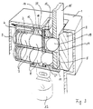
- Fig. 1 shows a schematic and perspective cut open an embodiment of a safety switch.
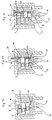
- FIG. 2a to 2c show the safety switch of Fig. 1 in section in different positions during operation.
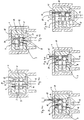
- Fig. 3 shows schematically and cut open perspective another embodiment of a safety switch.
- Fig. 4a to 4e show the safety switch of Fig. 3 in section in different positions during operation.
- the safety switch shown in Fig. 1 comprises a housing 1 which receives a block-shaped insert 2 which is provided with a plurality of parallel bores 3 arranged one above the other in two rows. Adjacent to a wall of the housing 1 is a wall 4 connected to the insert 2, which closes the bores 3 to the adjacent wall of the housing 1.
- the bores 3 open into a slot 5 which extends through the insert 2 perpendicular to the axes of the bores 3.
- the holes 3 each receive a pin 6.
- the pins 6 each comprise a foot piece 7 and, separately therefrom, a rounded head piece 8.
- the foot piece 7 has a blind hole for receiving one end of a compression spring 9, which is supported at the other end on the wall 4 and the associated pin 6 in the direction of the opposite wall of the housing 1 and presses so that the pins 6 can protrude with their head pieces 8 out of the holes 3 into the slot 5.
- the insert 2 with the spring-loaded pins 6 can be inserted into the housing 1 pre-assembled.
- the actuator 10 In the housing 1 is an essentially plate-shaped actuator 10 adjacent to the open ends of the holes 3 in the slot 5.
- the actuator 10 has a foot part 11 which is connected in an articulated manner to a plunger 12, in particular a straight plunger, of a switching device 13 arranged in the housing 1.
- the actuator 10 is movable along the adjacent end face of the insert 2 and has a series of through openings 14 for the pins 6. In the locked starting position, the pins 6 extend through the adjacent through opening 14 because the through openings 14 are in the locked position of the actuator 10 (Fig. 2a) are aligned with corresponding holes 3.
- the actuator 10 which is preferably guided on its two narrow sides, does not take up the full width of the slot 5, but leaves enough space to be able to insert a key 15 parallel to the actuator 10 via a corresponding slot 16 in the housing 1.
- the matching key 15 is provided with a pattern of receiving openings 17 in accordance with a coding provided.
- head pieces 8 of different lengths are used in such a way that part of the head pieces 8 has a length corresponding to the width of the slot 5 and another part has a shorter length.
- the shorter head pieces 8 lock the actuator 10 in the starting position (FIG. 2a), the longer head pieces 8 couple the actuator 10 with the key 15 in its inserted position (FIG. 2b) by falling into the receiving openings 17 of the latter, and also serve as a driver when pulling out the key 15.
- the key 15 has no receiving openings 17, so that in the inserted position of the key 15 the end faces of the foot pieces 7 of the Head pieces 8 are aligned with one another and with the adjacent wall of the slot 5 (FIG. 2b).
- the key 15 If the key 15 is now inserted, it presses the pins 10 which lock the actuator 10 and protrude from this with their head pieces 8 into the remaining part of the slot 5 with its leading, correspondingly bevelled edge against the force of the springs 9 back.
- the pins 6 When the key 15 arrives at the foot piece 11 of the actuator 10 (FIG. 2 b), the pins 6 have fallen into the receiving openings 17 of the key 15 and the key 15 has been pushed in further, since then the head pieces 8 are entirely from the actuator 10 and key 15 are recorded and carried along, possible and leads to actuation of the switching device 13 (Fig. 2c).
- the longer head pieces 8 not received by receiving openings 17 will lock the actuator 10 with respect to the insert 2.
- the actuator 10 is also not to be unlocked.
- the actuator 10 When the key 15 is withdrawn, the actuator 10 is withdrawn due to the head pieces 8 serving as drivers, until its foot part 11 strikes the insert 2. Then the key 15 is further pulled out, with the actuator 10 being locked, in the reverse order of insertion.
- the lengths of the head pieces 8 are to be chosen correspondingly shorter.
- pins 6 with head pieces 8 of the same length are used, while the foot pieces 7 also have the same length as in the previous embodiment.
- the actuator 10 is also additionally provided with a slot 18 and, in addition to each pin 6, a ball 19 is arranged adjacent to the respective head piece 8. The balls 19 are pressed by the pins 6 against the opposite wall of the slot 5 (FIG. 4a), the head pieces 8 extending over the width of the slot 18.
- the coding takes place here via a coding card 20 (FIG. 4b) which is inserted into the slot 18 and which has passage openings 21 in accordance with a coding provided.
- the thickness of the encoding card 20 is approximately the width of the width remaining between the actuator 10 and the opposite wall of the slot 5 less than the width of the slot 18.
- the pressing is also carried out.
- the thickness of the coding card 20 and the key 15 are expediently chosen to be somewhat smaller than or equal to the radius of the balls 19.
- Coding pieces 19 may be provided, of which those which do not fall into receiving openings 17 of the key 15 are designed as balls.
- the foot pieces 7 can also be omitted and the springs 9 can attack the head pieces 8 directly.
Landscapes
- Engineering & Computer Science (AREA)
- Computer Security & Cryptography (AREA)
- Push-Button Switches (AREA)
- Switch Cases, Indication, And Locking (AREA)
- Lock And Its Accessories (AREA)
Claims (9)
- Interrupteur de sécurité comprenant un boîtier (1) recevant un mécanisme de manoeuvre (13) pouvant être actionné par un organe d'actionnement (10) qui peut être déverrouillé au moyen d'une clef (15) susceptible d'être insérée dans le boîtier (1) et qui peut être déplacé d'une course prédéterminée par la clef dans le but d'actionner le mécanisme de manoeuvre (13), caractérisé en ce qu'une fente (5) s'étendant dans le sens d'introduction est agencée dans le boîtier (1), laquelle reçoit l'organe d'actionnement (10) et dans laquelle s'étendent une pluralité de pompes (6) disposées avec leur axe parallèlement les uns aux autres et perpendiculairement à la direction d'introduction de la clef (15) et rappelées par ressort en direction de la clef (15) introduite, au moins une partie desdites pompes verrouillant l'organe d'actionnement (10) par rapport au boîtier (1), la clef (15) présentant un motif codé d'orifices de réception (17) correspondant aux pompes verrouillées (6) afin de déverrouiller l'organe d'actionnement (10) et les pompes (6) étant susceptibles d'être codées de manière appropriée.
- Interrupteur de sécurité selon la revendication 1, caractérisé en ce que les pompes (6) comportent chacune une tête (8), lesquelles, avec la clef (15) insérée, viennent en alignement sur la face extérieure opposée à l'organe d'actionnement (10), les têtes (8) étant reçues dans l'organe d'actionnement (10) et éventuellement dans la clef (15).
- Interrupteur de sécurité selon la revendication 2, caractérisé en ce que les têtes (8) sont prévues avec deux différentes longueurs, les têtes (8) de grande longueur étant, avec la clef (15) insérée, reçues dans des orifices de passage (14) de l'organe d'actionnement (10) et dans les orifices de réception (17) de la clef (15), tandis que les têtes (8) de faible longueur sont reçues dans les orifices de passage (14) de l'organe d'actionnement (10).
- Interrupteur de sécurité selon la revendication 2, caractérisé en ce que les têtes (8) sont toutes de même longueur, les pompes (6) présentant dans leur axe des éléments de codage (19) distincts mobiles le long des orifices de passage (14) de l'organe d'actionnement (10).
- Interrupteur de sécurité selon la revendication 4, caractérisé en ce qu'une carte de codage (20) présentant des orifices de passage appropriés est insérée entre les extrémités côte à côte des têtes (8) et des éléments de codage (19).
- Interrupteur de sécurité selon la revendication 4 ou 5, caractérisé en ce que les éléments de codage (19) sont des billes.
- Interrupteur de sécurité selon l'une des revendications 1 à 6, caractérisé en ce que l'organe d'actionnement (10) comporte une embase (11) servant de butée lors de l'insertion de la clef (15).
- Interrupteur de sécurité selon l'une des revendications 1 à 7, caractérisé en ce que les pompes (6) sont disposées dans des trous (3) d'un insert (2) du boîtier (1).
- Interrupteur de sécurité selon l'une des revendications 2 à 8, caractérisé en ce que chaque pompe (6) comprend un pied (7) séparé de la tête (8) et sollicité par un ressort.
Applications Claiming Priority (4)
| Application Number | Priority Date | Filing Date | Title |
|---|---|---|---|
| GB939300100A GB9300100D0 (en) | 1993-01-05 | 1993-01-05 | Key operable lock mechanism |
| GB9300100 | 1993-01-05 | ||
| DE4315376 | 1993-05-08 | ||
| DE19934315376 DE4315376C1 (de) | 1993-05-08 | 1993-05-08 | Sicherheitsschalter |
Publications (2)
| Publication Number | Publication Date |
|---|---|
| EP0605820A1 EP0605820A1 (fr) | 1994-07-13 |
| EP0605820B1 true EP0605820B1 (fr) | 1996-05-29 |
Family
ID=25925732
Family Applications (1)
| Application Number | Title | Priority Date | Filing Date |
|---|---|---|---|
| EP19930120264 Expired - Lifetime EP0605820B1 (fr) | 1993-01-05 | 1993-12-16 | Interrupteur de sécurité |
Country Status (5)
| Country | Link |
|---|---|
| US (1) | US5606881A (fr) |
| EP (1) | EP0605820B1 (fr) |
| JP (1) | JP2859116B2 (fr) |
| BR (1) | BR9305402A (fr) |
| HK (1) | HK1003484A1 (fr) |
Families Citing this family (6)
| Publication number | Priority date | Publication date | Assignee | Title |
|---|---|---|---|---|
| SE508334C2 (sv) * | 1996-09-16 | 1998-09-28 | Assa Ab | Låsanordning |
| ATE302984T1 (de) * | 1998-05-08 | 2005-09-15 | Assa Ab | Kartenschloss |
| US7000078B1 (en) * | 1999-10-01 | 2006-02-14 | Stmicroelectronics Ltd. | System and method for maintaining cache coherency in a shared memory system |
| US6233985B1 (en) * | 2000-01-14 | 2001-05-22 | Fu-Chuan Huang | Coupling lock |
| US6595032B2 (en) * | 2001-11-01 | 2003-07-22 | Wen-Chen Lin | Lock cylinder-free lock device |
| EP2440726B1 (fr) * | 2009-06-10 | 2018-01-03 | Meir Avganim | Mécanisme de verrouillage à goupilles |
Family Cites Families (16)
| Publication number | Priority date | Publication date | Assignee | Title |
|---|---|---|---|---|
| DE2344473B2 (de) * | 1973-09-04 | 1976-04-29 | Josef Voss KG, 5040 Brühl | Zylinderkern in einem zylinderschloss mit flachschluessel |
| JPS5174798A (ja) * | 1974-12-24 | 1976-06-28 | Sanhorotsuku Jugen | Jomae |
| NO140145C (no) * | 1977-04-06 | 1979-07-11 | Elkem Spigerverket As | Anordning ved laas. |
| NO146441C (no) * | 1980-08-08 | 1982-09-29 | Elkem Spigerverket As | Anordning ved omkodbar hullkortlaas |
| WO1983001643A1 (fr) * | 1981-10-28 | 1983-05-11 | Pickles, Kenneth | Commutateur de securite |
| JPS60112967A (ja) * | 1983-11-21 | 1985-06-19 | 有限会社日本金具製作所 | シリンダ−錠 |
| DE3433048C2 (de) * | 1984-09-08 | 1986-10-02 | K.A. Schmersal Gmbh & Co, 5600 Wuppertal | Elektrischer Schalter |
| FR2613121B1 (fr) * | 1987-03-27 | 1993-12-10 | Telemecanique Electrique | Interrupteur a cle verrouillable par actionneur |
| JPS63153448U (fr) * | 1987-03-30 | 1988-10-07 | ||
| JPS63300178A (ja) * | 1987-05-29 | 1988-12-07 | 日本カバ株式会社 | 顧客確認機能を有する電子解施錠装置 |
| DE8800701U1 (de) * | 1988-01-21 | 1988-03-17 | Siemens AG, 1000 Berlin und 8000 München | Befehlsschalter |
| JPH01134166U (fr) * | 1988-03-08 | 1989-09-13 | ||
| NO166248C (no) * | 1988-05-24 | 1991-06-19 | Trioving As | Anordning ved omkodbar hullkortlaas. |
| DE4039652C1 (en) * | 1990-12-12 | 1992-03-05 | Kloeckner-Moeller Gmbh, 5300 Bonn, De | Detachable safety-interlock for electrical switch - has key guides chamfered to facilitate final engagement with coded cam |
| US5355701A (en) * | 1993-03-01 | 1994-10-18 | Tobias Marc W | Method and apparatus for decoding a pin tumbler lock |
| US5343724A (en) * | 1993-05-07 | 1994-09-06 | Trioving A.S. | Lock arrangement employing mechanically acting code card and key card |
-
1993
- 1993-12-16 EP EP19930120264 patent/EP0605820B1/fr not_active Expired - Lifetime
- 1993-12-28 JP JP33694293A patent/JP2859116B2/ja not_active Expired - Fee Related
- 1993-12-30 BR BR9305402A patent/BR9305402A/pt not_active IP Right Cessation
-
1995
- 1995-11-15 US US08/559,730 patent/US5606881A/en not_active Expired - Fee Related
-
1998
- 1998-03-25 HK HK98102551A patent/HK1003484A1/xx not_active IP Right Cessation
Also Published As
| Publication number | Publication date |
|---|---|
| JPH06223682A (ja) | 1994-08-12 |
| BR9305402A (pt) | 1994-08-02 |
| HK1003484A1 (en) | 1998-10-30 |
| JP2859116B2 (ja) | 1999-02-17 |
| EP0605820A1 (fr) | 1994-07-13 |
| US5606881A (en) | 1997-03-04 |
Similar Documents
| Publication | Publication Date | Title |
|---|---|---|
| EP1242705B1 (fr) | Outil pour debloquer un cylindre de fermeture | |
| DE60114487T2 (de) | Verriegelungsmechanismus für elektronische Schlösser | |
| DE69901698T2 (de) | Elektromagnetische verriegelungsvorrichtung | |
| DE4408024C5 (de) | Sicherheitsschalter | |
| DE4420372A1 (de) | Schließsystem, insbesondere für Kraftfahrzeuge und Gebäudeausrüstungen | |
| DE69300108T2 (de) | Mechanisches Schloss. | |
| DE3517660C2 (fr) | ||
| DE69418997T2 (de) | Zuhaltungsschloss mit veränderbarer Kombination für Tresortüren | |
| DE19632318A1 (de) | Verriegelungsvorrichtung für Schacht-Innendeckel | |
| EP0605820B1 (fr) | Interrupteur de sécurité | |
| DE2743769A1 (de) | Schloss und codierter schluessel zur betaetigung des schlosses | |
| DE2532076A1 (de) | Schloss | |
| DE8534096U1 (de) | Zylinderschloß mit einer Nachschließsicherung | |
| DE4315376C1 (de) | Sicherheitsschalter | |
| DE69906071T2 (de) | Mechanismus zur erlaubnis einer bewegung einer steuerungseinrichtung mittels der zusammensetzung eines kodes | |
| DE69401213T2 (de) | Schlüssel mit zwei abschrägungen am ende für ein sicherheitzylinderschloss und zylinderschloss dafür | |
| EP0756052B1 (fr) | Serrure cylindrique à goupilles et une clé pour une serrure à goupilles | |
| EP1050642B1 (fr) | Système de verrouillage anti-panique | |
| EP0943762A2 (fr) | Dispositif de verrouillage / deverrouillage avec une codage mécanique et électrique | |
| DE19712995C2 (de) | Möbelschloß | |
| DE3130322C2 (de) | "Schaltschloß" | |
| DE3533366A1 (de) | Aus flachschluessel und schliesszylinder bestehende schliessvorrichtung | |
| EP1132552B1 (fr) | Serrure à gorges | |
| EP0795664A2 (fr) | Serrure encastrée | |
| EP0119530B1 (fr) | Serrure à pêne coulissant, notamment pour coffre-fort |
Legal Events
| Date | Code | Title | Description |
|---|---|---|---|
| PUAI | Public reference made under article 153(3) epc to a published international application that has entered the european phase |
Free format text: ORIGINAL CODE: 0009012 |
|
| AK | Designated contracting states |
Kind code of ref document: A1 Designated state(s): CH FR GB IT LI |
|
| 17P | Request for examination filed |
Effective date: 19940618 |
|
| 17Q | First examination report despatched |
Effective date: 19951031 |
|
| GRAH | Despatch of communication of intention to grant a patent |
Free format text: ORIGINAL CODE: EPIDOS IGRA |
|
| GRAA | (expected) grant |
Free format text: ORIGINAL CODE: 0009210 |
|
| AK | Designated contracting states |
Kind code of ref document: B1 Designated state(s): CH FR GB IT LI |
|
| REG | Reference to a national code |
Ref country code: CH Ref legal event code: NV Representative=s name: ICB INGENIEURS CONSEILS EN BREVETS SA |
|
| ET | Fr: translation filed | ||
| ITF | It: translation for a ep patent filed | ||
| GBT | Gb: translation of ep patent filed (gb section 77(6)(a)/1977) |
Effective date: 19960903 |
|
| PLBE | No opposition filed within time limit |
Free format text: ORIGINAL CODE: 0009261 |
|
| STAA | Information on the status of an ep patent application or granted ep patent |
Free format text: STATUS: NO OPPOSITION FILED WITHIN TIME LIMIT |
|
| 26N | No opposition filed | ||
| REG | Reference to a national code |
Ref country code: GB Ref legal event code: IF02 |
|
| PGFP | Annual fee paid to national office [announced via postgrant information from national office to epo] |
Ref country code: CH Payment date: 20021119 Year of fee payment: 10 |
|
| PGFP | Annual fee paid to national office [announced via postgrant information from national office to epo] |
Ref country code: GB Payment date: 20021128 Year of fee payment: 10 |
|
| PGFP | Annual fee paid to national office [announced via postgrant information from national office to epo] |
Ref country code: FR Payment date: 20021206 Year of fee payment: 10 |
|
| PG25 | Lapsed in a contracting state [announced via postgrant information from national office to epo] |
Ref country code: GB Free format text: LAPSE BECAUSE OF NON-PAYMENT OF DUE FEES Effective date: 20031216 |
|
| PG25 | Lapsed in a contracting state [announced via postgrant information from national office to epo] |
Ref country code: LI Free format text: LAPSE BECAUSE OF NON-PAYMENT OF DUE FEES Effective date: 20031231 Ref country code: CH Free format text: LAPSE BECAUSE OF NON-PAYMENT OF DUE FEES Effective date: 20031231 |
|
| GBPC | Gb: european patent ceased through non-payment of renewal fee |
Effective date: 20031216 |
|
| REG | Reference to a national code |
Ref country code: CH Ref legal event code: PL |
|
| PG25 | Lapsed in a contracting state [announced via postgrant information from national office to epo] |
Ref country code: FR Free format text: LAPSE BECAUSE OF NON-PAYMENT OF DUE FEES Effective date: 20040831 |
|
| REG | Reference to a national code |
Ref country code: FR Ref legal event code: ST |
|
| PG25 | Lapsed in a contracting state [announced via postgrant information from national office to epo] |
Ref country code: IT Free format text: LAPSE BECAUSE OF NON-PAYMENT OF DUE FEES;WARNING: LAPSES OF ITALIAN PATENTS WITH EFFECTIVE DATE BEFORE 2007 MAY HAVE OCCURRED AT ANY TIME BEFORE 2007. THE CORRECT EFFECTIVE DATE MAY BE DIFFERENT FROM THE ONE RECORDED. Effective date: 20051216 |