EP0605717B2 - Automatisch startendes abtastsystem - Google Patents
Automatisch startendes abtastsystem Download PDFInfo
- Publication number
- EP0605717B2 EP0605717B2 EP93918513A EP93918513A EP0605717B2 EP 0605717 B2 EP0605717 B2 EP 0605717B2 EP 93918513 A EP93918513 A EP 93918513A EP 93918513 A EP93918513 A EP 93918513A EP 0605717 B2 EP0605717 B2 EP 0605717B2
- Authority
- EP
- European Patent Office
- Prior art keywords
- scanning
- user
- input device
- data
- software
- Prior art date
- Legal status (The legal status is an assumption and is not a legal conclusion. Google has not performed a legal analysis and makes no representation as to the accuracy of the status listed.)
- Expired - Lifetime
Links
- 238000000034 method Methods 0.000 claims abstract description 61
- 230000008569 process Effects 0.000 claims abstract description 58
- 230000000007 visual effect Effects 0.000 claims abstract description 7
- 238000012545 processing Methods 0.000 claims description 26
- 230000004044 response Effects 0.000 claims description 13
- 238000004891 communication Methods 0.000 claims description 7
- 230000003287 optical effect Effects 0.000 abstract description 27
- 230000005540 biological transmission Effects 0.000 abstract description 20
- 230000000977 initiatory effect Effects 0.000 abstract description 9
- 238000007639 printing Methods 0.000 abstract description 3
- 238000007906 compression Methods 0.000 description 12
- 238000012937 correction Methods 0.000 description 12
- 230000006835 compression Effects 0.000 description 9
- 238000012546 transfer Methods 0.000 description 8
- 230000009471 action Effects 0.000 description 6
- 238000003384 imaging method Methods 0.000 description 6
- 230000008859 change Effects 0.000 description 4
- 230000006837 decompression Effects 0.000 description 4
- 238000003780 insertion Methods 0.000 description 4
- 230000037431 insertion Effects 0.000 description 4
- 230000007246 mechanism Effects 0.000 description 4
- 230000002093 peripheral effect Effects 0.000 description 4
- 238000006243 chemical reaction Methods 0.000 description 3
- 238000013144 data compression Methods 0.000 description 3
- 238000010586 diagram Methods 0.000 description 3
- 230000006870 function Effects 0.000 description 3
- 238000001514 detection method Methods 0.000 description 2
- 239000000835 fiber Substances 0.000 description 2
- 238000012986 modification Methods 0.000 description 2
- 230000004048 modification Effects 0.000 description 2
- 230000035945 sensitivity Effects 0.000 description 2
- 239000013598 vector Substances 0.000 description 2
- 238000003491 array Methods 0.000 description 1
- 230000001413 cellular effect Effects 0.000 description 1
- 230000001419 dependent effect Effects 0.000 description 1
- 238000011982 device technology Methods 0.000 description 1
- 230000000694 effects Effects 0.000 description 1
- 230000005670 electromagnetic radiation Effects 0.000 description 1
- 238000005516 engineering process Methods 0.000 description 1
- 238000004519 manufacturing process Methods 0.000 description 1
- 239000000463 material Substances 0.000 description 1
- 238000012958 reprocessing Methods 0.000 description 1
- 230000001502 supplementing effect Effects 0.000 description 1
- 238000012360 testing method Methods 0.000 description 1
- 238000013519 translation Methods 0.000 description 1
Images



Classifications
-
- H—ELECTRICITY
- H04—ELECTRIC COMMUNICATION TECHNIQUE
- H04N—PICTORIAL COMMUNICATION, e.g. TELEVISION
- H04N1/00—Scanning, transmission or reproduction of documents or the like, e.g. facsimile transmission; Details thereof
- H04N1/00127—Connection or combination of a still picture apparatus with another apparatus, e.g. for storage, processing or transmission of still picture signals or of information associated with a still picture
- H04N1/00204—Connection or combination of a still picture apparatus with another apparatus, e.g. for storage, processing or transmission of still picture signals or of information associated with a still picture with a digital computer or a digital computer system, e.g. an internet server
- H04N1/00236—Connection or combination of a still picture apparatus with another apparatus, e.g. for storage, processing or transmission of still picture signals or of information associated with a still picture with a digital computer or a digital computer system, e.g. an internet server using an image reading or reproducing device, e.g. a facsimile reader or printer, as a local input to or local output from a computer
- H04N1/00241—Connection or combination of a still picture apparatus with another apparatus, e.g. for storage, processing or transmission of still picture signals or of information associated with a still picture with a digital computer or a digital computer system, e.g. an internet server using an image reading or reproducing device, e.g. a facsimile reader or printer, as a local input to or local output from a computer using an image reading device as a local input to a computer
-
- H—ELECTRICITY
- H04—ELECTRIC COMMUNICATION TECHNIQUE
- H04N—PICTORIAL COMMUNICATION, e.g. TELEVISION
- H04N1/00—Scanning, transmission or reproduction of documents or the like, e.g. facsimile transmission; Details thereof
- H04N1/00127—Connection or combination of a still picture apparatus with another apparatus, e.g. for storage, processing or transmission of still picture signals or of information associated with a still picture
- H04N1/00204—Connection or combination of a still picture apparatus with another apparatus, e.g. for storage, processing or transmission of still picture signals or of information associated with a still picture with a digital computer or a digital computer system, e.g. an internet server
- H04N1/00209—Transmitting or receiving image data, e.g. facsimile data, via a computer, e.g. using e-mail, a computer network, the internet, I-fax
-
- H—ELECTRICITY
- H04—ELECTRIC COMMUNICATION TECHNIQUE
- H04N—PICTORIAL COMMUNICATION, e.g. TELEVISION
- H04N1/00—Scanning, transmission or reproduction of documents or the like, e.g. facsimile transmission; Details thereof
- H04N1/00127—Connection or combination of a still picture apparatus with another apparatus, e.g. for storage, processing or transmission of still picture signals or of information associated with a still picture
- H04N1/00204—Connection or combination of a still picture apparatus with another apparatus, e.g. for storage, processing or transmission of still picture signals or of information associated with a still picture with a digital computer or a digital computer system, e.g. an internet server
- H04N1/00209—Transmitting or receiving image data, e.g. facsimile data, via a computer, e.g. using e-mail, a computer network, the internet, I-fax
- H04N1/00212—Attaching image data to computer messages, e.g. to e-mails
-
- H—ELECTRICITY
- H04—ELECTRIC COMMUNICATION TECHNIQUE
- H04N—PICTORIAL COMMUNICATION, e.g. TELEVISION
- H04N1/00—Scanning, transmission or reproduction of documents or the like, e.g. facsimile transmission; Details thereof
- H04N1/00127—Connection or combination of a still picture apparatus with another apparatus, e.g. for storage, processing or transmission of still picture signals or of information associated with a still picture
- H04N1/00204—Connection or combination of a still picture apparatus with another apparatus, e.g. for storage, processing or transmission of still picture signals or of information associated with a still picture with a digital computer or a digital computer system, e.g. an internet server
- H04N1/00236—Connection or combination of a still picture apparatus with another apparatus, e.g. for storage, processing or transmission of still picture signals or of information associated with a still picture with a digital computer or a digital computer system, e.g. an internet server using an image reading or reproducing device, e.g. a facsimile reader or printer, as a local input to or local output from a computer
-
- H—ELECTRICITY
- H04—ELECTRIC COMMUNICATION TECHNIQUE
- H04N—PICTORIAL COMMUNICATION, e.g. TELEVISION
- H04N1/00—Scanning, transmission or reproduction of documents or the like, e.g. facsimile transmission; Details thereof
- H04N1/0035—User-machine interface; Control console
- H04N1/00352—Input means
- H04N1/00355—Mark-sheet input
- H04N1/00358—Type of the scanned marks
- H04N1/0036—Alphanumeric symbols
-
- H—ELECTRICITY
- H04—ELECTRIC COMMUNICATION TECHNIQUE
- H04N—PICTORIAL COMMUNICATION, e.g. TELEVISION
- H04N1/00—Scanning, transmission or reproduction of documents or the like, e.g. facsimile transmission; Details thereof
- H04N1/0035—User-machine interface; Control console
- H04N1/00352—Input means
- H04N1/00355—Mark-sheet input
- H04N1/00368—Location of the scanned marks
- H04N1/00374—Location of the scanned marks on the same page as at least a part of the image
-
- H—ELECTRICITY
- H04—ELECTRIC COMMUNICATION TECHNIQUE
- H04N—PICTORIAL COMMUNICATION, e.g. TELEVISION
- H04N1/00—Scanning, transmission or reproduction of documents or the like, e.g. facsimile transmission; Details thereof
- H04N1/32—Circuits or arrangements for control or supervision between transmitter and receiver or between image input and image output device, e.g. between a still-image camera and its memory or between a still-image camera and a printer device
- H04N1/32037—Automation of particular transmitter jobs, e.g. multi-address calling, auto-dialing
- H04N1/32042—Automation of particular transmitter jobs, e.g. multi-address calling, auto-dialing with reading of job-marks on a page
-
- H—ELECTRICITY
- H04—ELECTRIC COMMUNICATION TECHNIQUE
- H04N—PICTORIAL COMMUNICATION, e.g. TELEVISION
- H04N2201/00—Indexing scheme relating to scanning, transmission or reproduction of documents or the like, and to details thereof
- H04N2201/0008—Connection or combination of a still picture apparatus with another apparatus
- H04N2201/0015—Control of image communication with the connected apparatus, e.g. signalling capability
- H04N2201/002—Selecting or switching between an image communication channel and a non-image communication channel
-
- H—ELECTRICITY
- H04—ELECTRIC COMMUNICATION TECHNIQUE
- H04N—PICTORIAL COMMUNICATION, e.g. TELEVISION
- H04N2201/00—Indexing scheme relating to scanning, transmission or reproduction of documents or the like, and to details thereof
- H04N2201/0008—Connection or combination of a still picture apparatus with another apparatus
- H04N2201/0034—Details of the connection, e.g. connector, interface
-
- Y—GENERAL TAGGING OF NEW TECHNOLOGICAL DEVELOPMENTS; GENERAL TAGGING OF CROSS-SECTIONAL TECHNOLOGIES SPANNING OVER SEVERAL SECTIONS OF THE IPC; TECHNICAL SUBJECTS COVERED BY FORMER USPC CROSS-REFERENCE ART COLLECTIONS [XRACs] AND DIGESTS
- Y10—TECHNICAL SUBJECTS COVERED BY FORMER USPC
- Y10S—TECHNICAL SUBJECTS COVERED BY FORMER USPC CROSS-REFERENCE ART COLLECTIONS [XRACs] AND DIGESTS
- Y10S345/00—Computer graphics processing and selective visual display systems
- Y10S345/902—Menu display
Definitions
- the present invention relates to a scanning system. More particularly the invention relates to an automatically initiated optical scanning system in which the presence of an optical record medium initiates scanning. According to aspects of the invention, with little or no intervention by the user, one or more processes and/or software are invoked and the scanned optical information is provided to the process or software as a result of the automatic scanning initiation. While the invention has many applications, the scanning system may be used, for example, in the environment of a personal computing system having various capabilities, which may include printing, the transmission of facsimile (“FAX”) and electronic mail (“E-mail”) messages, and the storage of scanned optical information.
- FAX facsimile
- E-mail electronic mail
- the document Patent Abstracts of Japan on JP-A-3013052 discloses a facsimile equipment capable of establishing either a facsimile communication link or a telephone communication link.
- the equipment comprises a sensor for detecting whether or not a document to be faxed has been inserted into the equipment.
- a user presses either a short dial key or a quick dial key it is checked, based on the sensor's output signal, whether a document has been inserted. If so, the facsimile number corresponding to the pressed key is read from memory, while otherwise a phone number is read so as to initiate a facsimile transmission or place a phone call.
- the document EP-A-0 398 185 discloses an electronic filing apparatus for filing documents using a mark sheet.
- the apparatus comprises a CPU, a keyboard, a CRT control circuit, a CRT, a memory, a companding circuit, a facsimile transmit/receive circuit, a modem, a scanner with an automatic paper feed device, a storage device, a printer and an interface circuit connecting the scanner, the storage device and the printer to a system bus.
- scanning by the scanner starts after an instruction has been input through a key operation of the keyboard.
- this prior art discloses a "command-driven system".
- the document EP-A-0 426 412 discloses an electronic apparatus combining a computer and a facsimile device. This document, like those described above, does neither disclose nor suggest a system in which the placement of a document alone is sufficient to initiate the document being drawn and scanned and the image of the scanned document being displayed.
- EP-A-0 556 067 discloses an integrated keyboard and scanner having a 'master mode' in which the user starts the scanning process by inserting a document into the scanner feeding slot.
- the scanner automatically starts scanning, initiates a communications protocol with the host computer and the host receives the scanned data into a 'spool' directory where it is stored for an application to retrieve it.
- EP-A-0 556 067 does not disclose means for automatically displaying the image of the scanned document.
- the basic elements of a scanning system include detector means for detecting the presence of an optical record medium, scanning means for generating a representation of optical information carried by the record medium, means for drawing the optical record medium past the scanning means so that the scanning means generates the representation in response to the detector detecting the presence of the medium, and means for displaying the representation.
- the means for displaying comprises a display device and resident software causing the display of the representation to be performed automatically and immediately.
- the optical record medium is in the form of flat sheets, such as sheets of paper.
- the invention in its broadest scope is not limited to use with paper and flat sheets. Aspects of the invention are applicable to use with optical record media formed from material other than paper (synthetic film, for example) and formed in shapes other than sheets.
- a housing contains the detector means and scanning means, and is adapted to accept the insertion of a record medium such that the detector means senses the insertion of the record medium.
- the housing also includes means for automatically drawing the record medium into the housing for scanning when the record medium is inserted and for automatically feeding the record medium out of the housing.
- a further aspect of the invention is that the automatic scanning, in addition to triggering the automatic display of the scanned optical information, triggers further automatic action, which may include (1) the automatic transmission of the scanned optical information to a process or software to, for example, a printer, an E-mail message system, a FAX message modem, or storage, or (2) the automatic presentation to a user of action choices by way of a "pop-up" menu, for example, on a visual display.
- the automatic and immediate display of the scanned optical information provides real time visual feedback to the user.
- Commands may be generated in one or more ways: (1) they may be predetermined and not user selectable; (2) they may be determined by the user prior to the initiation of scanning; (3) they may be recognized from symbols carried by the record media being scanned; and (4) they may be input or selected by the user subsequent to scanning.
- An embodiment of the system may employ more than one of these ways of generating commands.
- Cases (1), (2) and (3) are automatic in the sense that automatically initiated scanning causes further action without further intervention by the user.
- Case (4) is also automatic in the sense that option choices are presented to the user without prior intervention by the user.
- the scanning system may be configured as a device dedicated to a single purpose - for example, a scanner for transmitting FAXes.
- the automatic scanning of the record medium also initiates the commands necessary for the system to invoke a FAX transmission.
- the system may be embodied in a stand-alone FAX device or it could be a peripheral to a related device such as a host computer having FAX transmission capabilities.
- the user may exercise a choice prior to the initiation of scanning.
- the choice may be only a single choice or it may be multiple choices.
- an actuator means such as a button, which if pushed by the user prior to initiating scanning, generates the commands required to cause the scanned information, for example, to be printed by a peripheral printer. If the button is not pushed prior to initiating scanning, the system may operate in accordance with case (3) or case (4).
- the button may be dedicated to a single, predetermined purpose or it may be user programmable.
- the actuator means may permit the selection from multiple choices.
- commands may be affixed to the record medium prior to the initiation of scanning.
- Recognition means recognizes one or more symbols in the representation of optical information, each symbol representing one or more commands.
- a symbol such as the word "FAX"
- the symbol may be preprinted or added by the user by way of a sticker or writing.
- Auxiliary symbols may be associated with the command symbols.
- auxiliary symbols may be a telephone number to which a FAX is to be transmitted.
- the recognition means may be a part of the scanning means or, alternatively, may be part of processing means either physically housed with the scanning means and detector means or physically located apart from them, such as in a host computer.
- commands may be input or selected by the user subsequent to scanning.
- the initiation of scanning causes a pop-up window to appear on a monitor peripheral to a host computer to which the scanning means and detector means are also coupled.
- the pop-up window presents a menu with choices as to how the scanned optical information is to be used.
- the user selection results in the inputting of the commands required to invoke and execute the process or software representing that choice.
- case (4) need not require the use of a host computer and conventional monitor.
- One alternative for example, is a stand-alone device having a built-in visual display, such as a flat panel display screen.
- the stand-alone device may have the capability, for example, to transmit E-mail and/or FAXes and/or to print and/or to store in response to the initiation of scanning and the selection by the user of a desired action listed on the flat panel display screen.
- Output means with one or more output paths may also be associated with the detector means and scanning means.
- the output means may be responsive to one or more commands in order to selectively apply output signals to one or more of the paths.
- multiple paths may couple the output means respectively to devices in which E-mail, FAX. printer and storage processes and software are resident.
- the end result of the scanning system according to the present invention is that one or more processes and/or software are invoked and the scanned optical information is provided to the process or software. This is accomplished essentially automatically, in the sense explained above, with little or no intervention by the user.
- the detector means, scanning means and output means are housed together and function as a computer peripheral.
- the invention may be viewed as a new kind of computer input device, providing another way of inputting commands and data to a computer and, thus, supplementing traditional computer input devices (i.e., keyboard, mouse, etc.). This new way of inputting command and data may be characterized as "paper based computing.”
- communication may be via the computer's serial port.
- the scanning system may also provide for the sharing of an existing serial port.
- the scanning means may include means for data compression. Suitable data decompression may be provided in a host computer.
- data communication with a host computer is not limited to serial data protocol.
- Figure 1 is a symbolic diagram of an embodiment scanning system according to the present the invention.
- Figure 2 is partially exploded perspective view of an alternative scanning input device in combination with a computer monitor.
- Figure 3 is a drawing of a pop-up window with menu options displayed therein.
- Figure 4 is a flow chart representing processing by the input device for one embodiment according to the teachings of the invention.
- Figure 5 is a drawing of an input document having command symbols and auxiliary symbols.
- Figure 6 is a flow chart representing processing by the input device software resident on the host for the preferred embodiment according to the teachings of the invention.
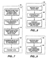
- Figure 7 is a flow chart of a process carried out by an embodiment of the input device for converting gray scale pixel data to black and white data compressing the data and transmitting it to the host for decompression and use or storage.
- Figure 8 is a flow chart of the process of compressing gray scale scanned data and transmitting it over a high speed link to the host.
- Figure 9 is a flow chart of the process of scanning gray scale data and transmitting it directly without compression from the input device to the host computer over a high speed, high bandwidth link.
- Figure 10 is a block diagram of the electronic circuitry in the scanning input device.
- FIG. 1 an embodiment of the scanning system according to the present invention is shown.
- the invention is in the environment of a personal computer system, the invention is not limited to such an environment.
- a host computer 10 is coupled via a data transfer means such as a data cable 12 to a scanning input device 14.
- a scanning input device 14 for clarity in presentation, the input device 14 of Figure 1 does not show all of the elements required in a practical scanning device. However, such devices and elements thereof are well known in the art.
- the data transfer means in the embodiment of Figure 1 and other embodiments may use any form of transmission of data to the host including transmission by (1) a data cable using any format and protocol (including parallel data transfer), (2) a local or wide area network, (3) a telephone link (including, for example, ISDN, fiber optic links, etc.), (4) electromagnetic radiation (including, for example, satellite communications, packet radio, cellular radio, etc.), (5) infrared, or (6) other suitable means.
- the data transfer means may be implemented by a serial data cable using RS232 serial data protocol in order to simplify the use with a host computer of a scanning input device embodying aspects of the invention. By using a host computer's RS232 serial data transfer capabilities it is not necessary to add additional hardware to the host computer as by adding an auxiliary board or card. However, the invention is not limited to using the RS232 serial data transfer format and protocol.
- Input device 14 has a housing containing scanning means (not shown) which uses known scanner technology to generate a representation of the optical information carried by the record medium 16 being scanned.
- the scanning means generates a representation of the optical information carried by the record medium.
- the scanning means may generate a plurality of parallel scan lines of pixel data wherein each scan line is the image of one line of black and white or gray scale data across on the record medium.
- Scan line 20 is typical of the plurality of scan lines.
- the record medium is a flat sheet of paper.
- paper A sheet of paper carrying optical information is also referred to herein as a "document.”
- the input device 14 also includes detector means, which may include one or more paper sensors such as sensors 22, for sensing the presence of the document to be scanned.
- the sensors sense the paper's insertion into or placement on the input device.
- the detector means generates a signal which triggers the scanning means in the input device to start the scanning process.
- Document 16 is drawn into the input device by means (not shown) for automatically drawing in the paper.
- the document 16 passes under a linear imaging array (not shown) such as a contact image sensor (“CIS”) array or, alternatively, a charge coupled device (“CCD”) array which generates scan lines of data.
- CIS contact image sensor
- CCD charge coupled device
- Figure 2 shows an alternative embodiment of the scanning input device according to the present invention.
- Figure 2 is a partially exploded view of a scanning input device 24, which may be mountable on a computer monitor 26 by means of clips 28 and 30 which snap into slots 32 and 34, respectively, formed in the housing of the monitor 26.
- the input device may be mounted by means other than clips and slots or may be mounted on other devices, such as on a keyboard, a printer or a computer housing.
- the input device may be integral with another device, such as a computer monitor or computer housing. Such arrangements reduce the footprint of the input device essentially to zero.
- the input device may be free-standing and not mounted on or fixed to another device.
- the input device has a housing 36 containing the detector means (not shown) and scanning means (not shown), in a manner similar to the embodiment of Figure 1 .
- a slot 38 is provided for inserting a paper sheet. The paper is automatically drawn into the housing 36 for scanning, is fed through the housing and is exited onto a paper catch tray 40, which may be omitted.
- Input device 24 may also be coupled via data transfer means to a host computer in the manner of Figure 1 .
- the input device 12 of Figure 1 and the input device 24 of Figure 2 also include output means (not shown) for generating an output signal in response to the representation of optical information generated by the scanning means.
- the output means includes means for formatting the output signal in a data protocol format for use for data transfer with the host computer.
- the formatted output signal may include a code indicating a detection of the paper presence by the detector means.
- the code is received by processing means, including software resident in the host 10, which triggers the host computer to read the port to which cable 12 is coupled to receive data from the input device.
- the detection code may be an interrupt which vectors processing by the host to a service routine which then reads the incoming serial data from the input device and stores it in a file.
- processing means including software
- the processing means may be physically located in the same housing as the scanning means, detector means and output means rather than in a separate enclosure or device such as a host computer.
- processing means in the host computer may include input device software facilitating the host computer's operation with the input device (hereafter the "ID host software").
- ID host software input device software facilitating the host computer's operation with the input device
- the input device which includes the detector means, scanning means and the output means, includes its own resident input device software which operates in cooperation with the ID host software.
- the ID software need not be separated.
- the software of the input device resident on the host also generates a menu presenting options to the user regarding what may be done with the optical information or scanned image.
- the ID software may also generate such a menu and provide the selection functions described below.
- the details of the pop-up window or menu are not critical to the invention.
- the input device software resident in the host may automatically generate the menu options by checking the bulk storage memory device (typically a hard disk) and the random access memory to determine what software and processes are resident and then generate a menu option for each capability of the host as represented by this software. The user may then select a menu option by, for example, pointing and clicking with a mouse or typing a highlighted letter in the menu option on the computer keyboard.
- Figure 3 shows a menu 42 that may be presented to the user. The user may then make a manual selection of what to do with the scanned image.
- the menu options may include, for example, "store,” “spreadsheet,” “word process,” “draw,” “send,” “fax,” “OCR,” and “cancel.” In practice, there may be fewer or more options and the options may differ from those shown in this example.
- the instructions or commands may, for example, originate in the scanned representation of optical information.
- processing means including means for recognizing one or more commands, which in turn includes input device software resident on the host, analyzes the output signal from the input device to find one or more commands therein which tells the ID host software what is to be done with the incoming data.
- commands may be generated in the input device - they may be predetermined or selected by a user prior to commencement of the scanning process.
- the processing means including ID host software or other suitable software, then passes a command or commands and a pointer to the appropriate software or process resident on the host to invoke the appropriate software, telling it what to do and telling it where the file is which contains the data just received from the input device.
- the file may be directly passed to the software or process rather than passing a pointer.
- all of these actions result automatically without any act by the user other than placing the paper in the scanning input device. This process is symbolized by the flow chart of Figure 4 which represent processing by the input device and the ID host software, respectively.
- block 54 represents the process of sensing the insertion of the paper to be scanned.
- the paper sensors may use, for example. microswitches, proximity sensors, or light beams which are interrupted by the presence of the paper. Light beams or other all-electronic sensors may be used for reliability greater than a mechanical microswitch.
- the details of implementation of the paper sensors is not critical to the invention.
- Block 56 represents the process of sending an interrupt to the host computer 10 to inform it that a document to be scanned has been inserted and that scanned data will be arriving shortly.
- the input device software resident on the host may poll the input device periodically to determine if a paper has been input for scanning. If it has, the acknowledgment message from the input device will serve to cause the ID host software to perform the processing described above.
- Block 58 represents the process of scanning the data from the document, including the process of scanning the document for one or more symbols which, if present, may indicate what the host is to do with the scanned image data.
- the process derives gray scale data from the images on the document. Although something other than 256 levels could be used, in one embodiment, 256 gray scale levels are used and an 8-bit byte is generated for each pixel on each scan line.
- the gray scale data is not permanently stored in a file for later reprocessing such as when the discrimination threshold changes. but in alternative embodiments. the gray scale data may be stored in a file in random access memory ("RAM") or on a bulk storage device such as a hard disk, an optical disk, a recordable compact disk, a streaming tape, etc.
- RAM random access memory
- scanning means in the input device may include symbol recognition software that recognizes symbols on the document to be scanned, which symbols may indicate whether the document is to be FAXed, sent as E-mail, etc.
- the particular recognition software employed is not critical to the invention. Symbol recognition software and processes are well known.
- the symbols may be either preprinted on the document, drawn on the document by hand by the user, or carried by a sticker or label placed on the document by a user. Symbols may be printed on the document using software that has predefined graphic images for every type command which the input device may execute and which may print these symbols on the document to be scanned by running the document through a printer, etc. Automatic processing of the scanned image may be started by the recognition of the symbol by the scanning means without the user having to press any buttons, make any menu selections, etc. Alternatively, symbol recognition may take place in the scanning means, which may be in a host computer.
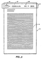
- Figure 5 represents one way of using this input device technology where the symbols may be placed in a predetermined "hot zone" 64.
- the hot zone may be some predetermined portion at the top edge of the paper to be scanned, but in other embodiments it may be any predetermined portion of the paper. Use of a hot zone reduces the processing requirements of the recognition software because it need not search the entire document.
- an E-mail symbol 66 and a FAX symbol 68 are present in the hot zone.
- the block 58 in Figure 4 represents, in addition to scanning the main body 70 of the document 72 in Figure 5 , the process of scanning these symbols in the hot zone, recognizing them and translating these symbols into a command or set of commands that will be used by the processing means including the ID host software to invoke the proper software or process.
- the command symbols may be stickers that are affixed to the document by a user.
- the use of stickers to carry symbols has certain advantages, including, for example: convenience in use; the symbol recognition software may be pre-trained to recognize specific symbols carried by the sticker.
- the stickers may be removable so as not to permanently deface the document.
- command symbols may be printed in the hot zone, as by a preprinted form or by printing done by the user on a printer or even a rubber stamp.
- the command symbol may be hand drawn in the hot zone.
- the recognition software in the input device may have to be trained to recognize the hand drawn symbols.
- Auxiliary or attribute symbols may be included in proximity to command symbols to more precisely control the processing commanded by the command symbol.
- the E-mail symbol 66 causes the input device recognition means to recognize the fact that the scanned image is to be sent as an E-mail image and issue a command or set of commands to invoke the E-mail software in the host.
- the auxiliary or attribute symbol in this case is shown at 80 and is a person's name "Pierre-Alain.”
- the auxiliary symbol is also analyzed by the recognition software. It may, for example, compare it to a list of previously stored symbols representing the names of all the people to whom the user may wish to send a FAX.
- the symbol need not be alphanumeric. For example, it may be a geometric shape such as a multisided figure: a hexagon, for example.
- auxiliary or attribute symbols is not mandatory.
- the presence of a command symbol and the absence of an auxiliary symbol may, for example, result in a prompt asking the user to supply needed auxiliary information or may result in the generation of default auxiliary commands.
- the sticker itself may have a secondary "hot zone" which the recognition software associates with the command appearance and in which the recognition software will look for attributes such as FAX phone numbers, etc.
- the secondary hot zone may be within the sticker itself or in proximity thereto at a location with respect to the command symbol expected by the recognition software.
- a single sticker may be used for all commands to the input device software with specific "command boxes" within the perimeter of the sticker which the user may blacken out with a pencil or pen to indicate which particular command of the overall set of input device commands is desired by the user.
- Such an arrangement may also be employed in the case of preprinting.
- the stickers in this set which need supplementary symbols such as a name from a FAX directory or a FAX phone number may have letter and/or number boxes within the perimeter of the sticker, including, for example, sets of letters of the alphabet and/or sets of numbers from 0 to 9 so that a name or shortened form of a name may be indicated by marking a letter in each alphabet set and a phone number may be indicated by marking each a number in each number set.
- the sticker may have two hot zones - one of which allows selection of the particular command to be invoked by marking the command.
- the marking may be done in any predetermined way which is recognizable by the recognition software. For example, there may be a defined area adjacent the command, letter or number which is darkened by the user by means of a writing instrument. These alternatives may also be implemented in the case of preprinting.
- the input processing just described requires that the user know only the name of the person to whom a FAX or E-mail message is to be sent. The user need not know how to invoke the appropriate software or process and run it.
- box 60 represents the process of transmitting the scanned image data from the document inserted by the user.
- the scanned image data is compressed by the scanner means. In one embodiment, this is accomplished in the input device software on the scanner side of the RS232 serial data cable before being transmitted to the host computer 10 and this process is included within the process of transmitting the data represented by box 60.
- Any known data compression process may be used for the pretransmission compression process, and the details of how it is done are not critical to the invention. For example, known FAX machine Group III or Group IV compression algorithms may be used.
- the input device software then waits for the next document to be inserted as represented by box 62 and upon such input the loop returns to its start input.
- FIG. 6 there is shown a flow chart for the processing performed by input device software resident on the host.
- an interrupt driven scheme is used.
- Box 102 represents the process of receiving the interrupt from the scanning input device 14 in Figure 1 resulting from the paper sensors sensing the presence of a document to be scanned.
- the interrupt may, for example, cause the host computer 10 to stop whatever it is doing and vector the host computer processing to an interrupt service routine assigned to the interrupt number assigned to input device 14 as symbolized by box 104.
- the data scanned from the document is then received from the RS232 cable and, if the input to the RS232 cable has been data compressed, the incoming data is decompressed by the input device software resident on the host computer, for example, and is stored in a file as symbolized by box 106.
- the compression and decompression process may be omitted at the cost of longer transmission times.
- Box 108 represents the process of storing the received data in a file on a hard disk, RAM, etc.
- Box 110 represents the process of recognizing commands as to what is to be done with the incoming data.
- the commands regarding what is to be done with the data arriving from the input device are manually entered by the user by selections from a menu of options which automatically appears whenever the interrupt from the input device occurs.
- the menu of options appears automatically, for example, as a pop-up window as symbolized by box 111 in Figure 1 and by Figure 3 .
- An image of the incoming data is also displayed in a pop-up window.
- the process of box 110 represents the process of recognizing commands in the data stream by symbol recognition means, which may be a part of the processing means in the host computer or it may be a part of the scanning means, and is part of the process of scanning the image on the document 16 represented by box 58 of Figure 4 .
- the symbol recognition process recognizes, in one of the ways described above or some equivalent way, a particular symbol on the document which has been selected by the user as representing the desired processing of the data scanned in by the input device. The symbol selection is by one of the ways described above or some equivalent manner.
- a translation to the appropriate command is made by the input device software resident on the scanner 14 and the command is sent over cable 12 to the host.
- the input device software resident on the host then receives and recognizes these commands and issues the appropriate commands to the software on the host capable of doing the function indicated by the commands received from the input device symbol recognition software as symbolized by box 112.
- the ID host software may also transmit, if they are present, appropriate auxiliary or attribute data to the selected host software such as the FAX phone number or E-mail address to allow the selected host software to complete processing the data. This process is also symbolized by box 112.
- auxiliary or attribute data may be generated by any of the symbol recognition processes described above carried out by the input device software resident on the scanning mechanism, or it may be done by the input device software resident on the host in response to data entered manually by the user through the keyboard, and each of these alternative embodiments is intended to be symbolized by the process of box 112 in Figure 6 .
- the software or process invoked by the commands are usually resident on the host or some external bulk storage memory device, they could also be resident on a file server coupled to the host via a local area network. Alternative embodiments in which the invoked software or process is resident on a file server coupled to the host 10 by a network or other link is symbolized by the network pigtail 113 in Figure 1 .
- FIG. 7 there is shown a flow chart of the process of compressing and transmitting data in an embodiment for transmitting in RS232 serial data protocol.
- the flow chart of Figure 7 is encircled by a dashed box labeled 60 to symbolize the fact that the process shown in Figure 7 is a more detailed description of one embodiment of the process symbolized by box 60 in Figure 4 .
- the process symbolized by Figure 7 is only one example of an embodiment represented by box 60 in Figure 4 .
- Box 60 also symbolizes other embodiments in which other transmission formats and protocols, including parallel transmission is used or in which no data compression is used.
- Scanning mechanisms used in the scanning input device may be of the type which generate pixel data using 256 or more gray levels. This translates to eight bits per pixel.
- serial protocol transmission in which bandwidth is limited, it is preferred to transmit black and white data where each pixel's data is a single bit which is either a 1 or 0 representing black or white.
- This conversion from gray scale to black and white is followed by compression of the black and white data and serial transmission of the compressed data. The result is large savings in transmission time.
- Such compression techniques are known per se. The particular implementation of the compression scheme is not critical to the invention.
- the first step in this process is symbolized by block 114 where the gray scale data is received from the process symbolized by box 58 in Figure 4 .
- a black/white discrimination threshold level is selected to be used in converting the gray scale data to black and white information as symbolized by block 116. If, for example, 256 gray levels are present, the discrimination threshold may be arbitrarily preset at 128 so that any gray level having a decimal value below 128 is set at binary 0 for black and any pixel having a gray level greater than 128 may be set at binary 1 for white.
- the process of selecting the black/white discrimination threshold symbolized by block 116 may be done by any of a number of ways.
- One method is to select a predetermined threshold level such as 128 or some other level which has been experimentally determined to work best in most cases.
- the user may change the threshold for each document by changing a "preferences" attribute in a control panel or set-up menu for the input device software.
- a selectable default value such as the last value selected or some predetermined value may be used if the user fails to specify a preference.
- the input device software will automatically scan the document, send the data to the host in any of the ways described herein, and the input device software resident on the host will then cause a pop-up window to appear on the screen where the image of the scanned document appears.
- the user may then inspect the image to determine readability and, if the contrast or readability is not to the user's liking, the user may then change the discrimination threshold.
- the gray scale data will be stored in a memory associated with the input device 14 of Figure 1 .
- the input device host resident software receives the user's new preference for the discrimination threshold and sends it to the input device software resident on the scanner 14.
- the gray scale data is then reprocessed with the new discrimination threshold and new black and white data is generated and sent to the input device host resident software for redisplay. This process continues until the scanned image displayed on the host meets the user's needs.
- the black/white discrimination threshold may be selected automatically based upon the scan results of a test pattern with various contrasting patterns printed on the input document.
- the gray scale data is converted to black and white data as symbolized by block 118.
- Blocks 120 and 122 in Figure 7 represent the process of compressing the black and white data and transmitting it on the data cable to the host computer, respectively.
- the steps of selecting a discrimination threshold and converting the pixel data from gray scale to black and white may be omitted and the gray scale data may be transmitted directly to the host or the gray scale data may be compressed and then transmitted to the host for decompression and display.
- Figure 8 represents the transmission process of block 60 in Figure 4 where gray scale data is received from the linear imaging array (block 124), compressed using any known compression algorithm suitable for compressing gray scale data (block 126), and transmitted over a high speed link to the host (block 128).
- Figure 9 represents the embodiments wherein the transmission process of box 60 in Figure 4 comprises the steps of receiving the gray scale data (block 130) and transmitting it directly over a high speed, high bandwidth link to the host as symbolized by block 132.
- the uncompressed gray scale data or the compressed gray scale data may be transmitted to the host.
- the scanner system of the present invention may operate wholly in the digital domain or in some combination of the digital and analog domains.
- Implementations in the digital domain may include, for example, hard-wired logic (using, for example, components and/or application specific integrated circuits or some combination of the two), software and/or firmware controlled microprocessors. software and/or firmware controlled digital signal processors or any combination of such building blocks.
- FIG. 10 there is shown a block diagram of the electronics of the detector means, scanning means and output means resident in the scanning input device 14 of Figure 1 .
- the presence of a document is sensed by a paper sensor 150 which may generate an interrupt to a microprocessor 194 or the paper sensor may be polled periodically by the microprocessor.
- the microprocessor which may be a Zilog Z180, for example, then automatically starts the scanning processing by addressing, for example, a stepper motor driver 196, causing a stepper motor to drive means for drawing the document into the input device and moving it past a sensor array 198.
- the sensor array generates a plurality of scan lines of analog gray scale pixel data as the document moves past it.
- the gray scale data may be corrected to account for different sensitivities of the image cells in the contact image sensor.
- Various imaging cells of the sensor may have different sensitivities caused by manufacturing nonuniformities. Correction is done by the combination of a correction RAM 200, a digital-to-analog converter 202 and a differential amplifier 204.
- Each imaging cell i.e., pixel position. has a corresponding memory location in the image sensor 198. In each memory location, a correction number is stored, a portion of which is dedicated to correcting the white level of the cell and another portion of which is dedicated to correcting the dark current.
- the correction numbers are converted to analog signal levels by the digital to analog converter and the resulting signals are applied via bus 206 to change the gain and reference voltages of the amplifier 204 to correct the white level and dark current level of the amplifier 204.
- the correction numbers are addressed sequentially via address bus 208 as the gray scale pixel value from each corresponding imaging cell is read out on bus 210 and coupled to an amplifying input of the amplifier 204.
- correction numbers stored in correction RAM 200 are also the mechanism by which changes in conversion threshold are made as described earlier to convert the gray scale data to black and white data.
- changes in conversion threshold are made as described earlier to convert the gray scale data to black and white data.
- the midway point between the dark current and white current levels is also shifted in the same direction as the shift in the correction.
- This has the effect of changing the discrimination threshold value so that the decisions as to which gray scale pixel values are assigned to black and which are assigned to white.
- changes in the dark current and white level correction numbers may also be made in opposite directions to alter the dynamic range of the imaging cell. This may or may not change the discrimination threshold level depending upon the relative movement of the dark current and white level correction numbers.
- the gray scale pixel data is applied to the input of an analog-to-digital converter 212 where the analog pixel data is converted to, preferably, 6-8 bit gray scale data.
- the most significant bit of this gray scale data is stripped off the bus 214 as a one bit signal on bus 216.
- the stream of bits on bus 216 are shifted into a serial-in-parallel-out shift register 218 until a full byte of data has accumulated.
- the data in shift register 218 is then output in parallel on the microprocessor data bus 220.
- the 6 to 8 bits of gray scale data on bus 214 are also loaded via bus 222 into a buffer 224.
- the single bit data on bus 216 is essentially the black and white data converted from the gray scale data assuming that the conversion threshold is midway between the dark current level and the white level since the most significant bit is used.
- This black and white data may then be collected by the microprocessor 194 and sent directly to the host via a Universal Asynchronous Receiver Transmitter ("UART") 226 and a serial cable (not shown) connected to the host or the black and white data may be compressed.
- UART Universal Asynchronous Receiver Transmitter
- serial cable not shown
- a UART interfaces serial to parallel data streams and vice-versa.
- the black and white data in one embodiment, is sent to a conventional compression process for run length encoding, etc.
- the compression process is carried out by microprocessor 194 on the black and white data.
- the gray scale data stored in buffer 224 may be read by the microprocessor 224, compressed and then transmitted to the host via the UART 226.
- the gray scale data may be collected from the buffer 224 and sent directly to the host without compression via the serial link and UART 226 or a high speed, parallel cable (not shown) coupled to parallel port driver 228.
- the microprocessor 194 executes the compression algorithm and all the other instructions necessary for the processing described herein from RAM 230 which is loaded with the program from the input device software resident on the host computer at boot time through the parallel port driver 228.
- EEPROM 232 stores a small amount of boot code which gets the microprocessor up and running at boot time and causes it to request downloading of its program from the host.
- Box 234 represents a series of latches, LEDS and front panel buttons.
- the button may cause an interrupt to indicate when it is pushed or it may be periodically polled.
- Box 234 also represents the driver for the LED which may be turned on by the microprocessor 194 by setting a bit in one of the latches. Other bits in the latches may be set according to whatever configuration the input device is programmed to assume and whatever is the current status such "send gray scale data,” “send compressed gray scale data over the parallel port,” “send compressed black and white data over the serial port,” “a paper has been inserted for scanning,” etc.
Landscapes
- Engineering & Computer Science (AREA)
- General Engineering & Computer Science (AREA)
- Multimedia (AREA)
- Signal Processing (AREA)
- Computing Systems (AREA)
- Computer Vision & Pattern Recognition (AREA)
- Automation & Control Theory (AREA)
- Facsimiles In General (AREA)
- Facsimile Scanning Arrangements (AREA)
- Vehicle Body Suspensions (AREA)
- Optical Communication System (AREA)
Claims (6)
- System umfassend eine scannende Eingabeeinrichtung (14), einen Computer (10), und Mittel (12) zum Verbinden der Eingabeeinrichtung (14) mit dem Computer zur Herstellung einer Kommunikation zwischen ihnen, wobei die Eingabeeinrichtung umfaßt Detektormittel (22) zum Erfassen des Einlegens eines Dokuments (16) durch einen Benutzer, Scanmittel zur Erzeugung von Bilddaten, die das Bild des Dokuments repräsentieren, und auf die Detektormittel ansprechende Mittel zum Ziehen des Dokuments in eine Scanbeziehung mit den Scanmitteln derart, daß die Scanmittel die Bilddaten erzeugen, wobei das Einlegen allein zum Einleiten des Ziehens ausreicht, und der Computer Mittel (26) zum automatischen und sofortigen Darstellen als Reaktion auf das Einlegen und den Empfang der Bilddaten einer visuellen Darstellung der Bilddaten aufweist, wobei der Computer (10) Mittel (26) zur Anzeige umfaßt, und zwar als Antwort auf das Einlegen einer Mehrzahl benutzerwählbarer Optionen zur Verarbeitung der Bilddaten.
- System nach Anspruch 1, bei dem die Eingabeeinrichtung (14) in der Lage ist, an den Computer (10) einen Interrupt zu senden, wenn ein Dokument (16) durch einen Benutzer eingelegt wird, und der Computer (10) in der Lage ist, die visuelle Darstellung als Antwort auf den Empfang des Interrupts und der Bilddaten anzuzeigen.
- System nach Anspruch 1, bei dem der Computer in der Lage ist, die Mehrzahl benutzer- wählbarer Optionen als Antwort auf den Empfang des Interrupts anzuzeigen.
- System nach Anspruch 1, bei dem der Computer in der Lage ist, periodisch die Eingabeeinrichtung (14) abzufragen, um festzustellen, ob ein Dokument (16) durch einen Benutzer eingelegt wurde, wobei die Eingabeeinrichtung (14) in der Lage ist, an den Computer als Antwort auf die Anfrage eine Bestätigung zu senden, wenn ein Dokument durch einen Benutzer eingelegt wurde, und der Computer (10) in der Lage ist, die visuelle Darstellung als Antwort auf den Empfang der Bestätigung und der Bilddaten anzuzeigen.
- System nach Anspruch 4, bei dem der Computer (10) in der Lage ist, die Mehrzahl benutzer- wählbarer Optionen als Antwort auf den Empfang der Bestätigung anzuzeigen.
- System nach einem der Ansprüche 1, 3 oder 5, bei dem der Computer (10) ferner Mittel zur Feststellung aufweist, welche Option von dem Benutzer gewählt wurde sowie zum Aufruf eines Prozesses zur Verarbeitung der Bilddaten, welcher der von dem Benutzer gewählten Option entspricht.
Applications Claiming Priority (5)
| Application Number | Priority Date | Filing Date | Title |
|---|---|---|---|
| US92216992A | 1992-07-29 | 1992-07-29 | |
| US922169 | 1992-07-29 | ||
| US988404 | 1992-12-09 | ||
| US07988404 US5499108C1 (en) | 1992-07-29 | 1992-12-09 | Document-driven scanning input device communicating with a computer |
| PCT/US1993/007164 WO1994003994A1 (en) | 1992-07-29 | 1993-07-29 | Automatically initiated scanning system |
Publications (3)
| Publication Number | Publication Date |
|---|---|
| EP0605717A1 EP0605717A1 (de) | 1994-07-13 |
| EP0605717B1 EP0605717B1 (de) | 1999-10-06 |
| EP0605717B2 true EP0605717B2 (de) | 2008-12-17 |
Family
ID=27129835
Family Applications (1)
| Application Number | Title | Priority Date | Filing Date |
|---|---|---|---|
| EP93918513A Expired - Lifetime EP0605717B2 (de) | 1992-07-29 | 1993-07-29 | Automatisch startendes abtastsystem |
Country Status (8)
| Country | Link |
|---|---|
| US (1) | US5499108C1 (de) |
| EP (1) | EP0605717B2 (de) |
| JP (1) | JPH06511614A (de) |
| AU (1) | AU4793993A (de) |
| CA (1) | CA2120151A1 (de) |
| DE (1) | DE69326677T2 (de) |
| ES (1) | ES2136665T3 (de) |
| WO (1) | WO1994003994A1 (de) |
Families Citing this family (136)
| Publication number | Priority date | Publication date | Assignee | Title |
|---|---|---|---|---|
| US8352400B2 (en) | 1991-12-23 | 2013-01-08 | Hoffberg Steven M | Adaptive pattern recognition based controller apparatus and method and human-factored interface therefore |
| US5477238A (en) * | 1992-02-13 | 1995-12-19 | Aharanson; Ophira R. | Method of and station for integrated typed data and optically scanned data capture for computer interfacing and the like |
| US5499108C1 (en) | 1992-07-29 | 2001-01-16 | Primax Electronics Ltd | Document-driven scanning input device communicating with a computer |
| US5799190A (en) * | 1994-08-09 | 1998-08-25 | Apple Computer, Inc. | Communications coprocessor for realizing bidirectional isochronous communications link with host computer |
| US6885470B1 (en) | 1995-03-06 | 2005-04-26 | Matsushita Electric Industrial Co., Ltd. | Electronic mail system |
| US6778287B1 (en) | 1995-03-06 | 2004-08-17 | Matsushita Electric Industrial Co., Ltd. | Electronic mail system |
| JP3160177B2 (ja) | 1995-03-06 | 2001-04-23 | 松下電器産業株式会社 | ファクシミリ型電子メール装置 |
| JPH08265468A (ja) * | 1995-03-20 | 1996-10-11 | Brother Ind Ltd | ファクシミリ装置 |
| JP3720419B2 (ja) * | 1995-06-09 | 2005-11-30 | 株式会社東芝 | 画像処理装置 |
| US5999708A (en) | 1995-07-31 | 1999-12-07 | Canon Kabushiki Kaisha | Method and apparatus for copier request and retrieval of files from multiple computers |
| US5752079A (en) * | 1995-09-08 | 1998-05-12 | Canon Kabushiki Kaisha | System for reading parameters from portable key module and transferring these parameters to controller to effect distribution and storage of electronic document data throughout network |
| US5582470A (en) * | 1995-09-12 | 1996-12-10 | Silitek Corporation | Scanner housing |
| EP0768597B1 (de) * | 1995-10-13 | 2004-06-09 | Dov Aharanson | Integrierte Erfassungsgeräte für Rechner |
| US5812278A (en) * | 1995-10-20 | 1998-09-22 | Matsushita Graphic Communication Systems, Inc. | Image communicating method, facsimile type electronic mail apparatus and facsimile apparatus |
| US5920734A (en) * | 1996-02-01 | 1999-07-06 | Microsoft Corporation | System for providing electrical power to a computer input device according to the interface types through the shared use of wires and a voltage clamp |
| US6064497A (en) * | 1996-03-08 | 2000-05-16 | Intel Corporation | Low cost digital scanners |
| US6147775A (en) * | 1996-03-15 | 2000-11-14 | Brother Kogyo Kabushiki Kaisha | Facsimile control system |
| US5790278A (en) * | 1996-03-20 | 1998-08-04 | Eastman Kodak Company | Scanner with drawer load and exit |
| EP1395033B1 (de) * | 1996-04-12 | 2007-11-28 | Matsushita Electric Industrial Co., Ltd. | Elektronisches Postsystem |
| US5935223A (en) * | 1996-05-21 | 1999-08-10 | Texas Instruments Incorporated | System for blocking access to a computer device using a glue logic circuit operable to force a target computer device to perform a target abort |
| US5875038A (en) * | 1996-05-28 | 1999-02-23 | Gerber Scientific, Inc. | Facsimile queuing and transmission system |
| US5663813A (en) * | 1996-05-29 | 1997-09-02 | Primax Electronics, Ltd. | Image scanning device mounted to computer case |
| IT1285407B1 (it) † | 1996-06-05 | 1998-06-03 | Olivetti Lexicon S P A | Metodo e sistema per l'invio di documenti tramite posta elettronica |
| EP0817461A3 (de) | 1996-06-25 | 2000-08-16 | Matsushita Electric Industrial Co., Ltd. | Bildinformationsverarbeitungsgerät und Bildinformationsübertragungsgerät |
| EP1016215A2 (de) * | 1996-06-27 | 2000-07-05 | Michael J. Ure | Tastatur unterverwendung von hochgeschwindigkeitsmultiplex-serienverbindung diei/o vorrichtung einschliesst |
| US5822080A (en) * | 1996-09-04 | 1998-10-13 | Hewlett-Packard Company | Desktop space-saver scanner |
| US5754748A (en) * | 1996-09-13 | 1998-05-19 | Lexmark International, Inc. | Download of interpreter to a printer |
| DE69729922T2 (de) * | 1996-09-19 | 2005-08-25 | Canon K.K. | Bildlesesystem und -verfahren |
| US6771381B1 (en) | 1998-11-13 | 2004-08-03 | Laurence C. Klein | Distributed computer architecture and process for virtual copying |
| US7602518B2 (en) * | 1996-11-21 | 2009-10-13 | Ricoh Company, Ltd. | Automatic and transparent document archiving |
| US6704118B1 (en) | 1996-11-21 | 2004-03-09 | Ricoh Company, Ltd. | Method and system for automatically and transparently archiving documents and document meta data |
| US5978477A (en) * | 1996-11-21 | 1999-11-02 | Ricoh Company Limited | Automatic and transparent document archiving |
| US7170629B2 (en) * | 1998-11-13 | 2007-01-30 | Ricoh Company, Ltd. | Automatic and transparent document archiving |
| KR19980052704A (ko) * | 1996-12-24 | 1998-09-25 | 김광호 | 컴퓨터를 이용한 다기능장치 제어장치 및 방법 |
| US6786420B1 (en) | 1997-07-15 | 2004-09-07 | Silverbrook Research Pty. Ltd. | Data distribution mechanism in the form of ink dots on cards |
| US5913072A (en) * | 1997-04-08 | 1999-06-15 | Wieringa; Fred | Image processing system in which image processing programs stored in a personal computer are selectively executed through user interface of a scanner |
| US6084691A (en) * | 1997-04-10 | 2000-07-04 | Microtek International, Inc. | Multi-purpose scanner integrated into a computer |
| US6112014A (en) * | 1997-05-16 | 2000-08-29 | Kane; Patrick | Photocopy machine capable of storing and transmitting image data |
| JP3464589B2 (ja) * | 1997-06-05 | 2003-11-10 | パナソニック コミュニケーションズ株式会社 | 中継機能付き通信装置及びその制御方法 |
| US6618117B2 (en) | 1997-07-12 | 2003-09-09 | Silverbrook Research Pty Ltd | Image sensing apparatus including a microcontroller |
| US6624848B1 (en) | 1997-07-15 | 2003-09-23 | Silverbrook Research Pty Ltd | Cascading image modification using multiple digital cameras incorporating image processing |
| US20040119829A1 (en) | 1997-07-15 | 2004-06-24 | Silverbrook Research Pty Ltd | Printhead assembly for a print on demand digital camera system |
| US6879341B1 (en) | 1997-07-15 | 2005-04-12 | Silverbrook Research Pty Ltd | Digital camera system containing a VLIW vector processor |
| US7110024B1 (en) | 1997-07-15 | 2006-09-19 | Silverbrook Research Pty Ltd | Digital camera system having motion deblurring means |
| US6690419B1 (en) | 1997-07-15 | 2004-02-10 | Silverbrook Research Pty Ltd | Utilising eye detection methods for image processing in a digital image camera |
| US6002496A (en) * | 1997-08-06 | 1999-12-14 | Acer Pheripherals, Inc. | Sheet-fed scanner with a preview function |
| US6006226A (en) * | 1997-09-24 | 1999-12-21 | Ricoh Company Limited | Method and system for document image feature extraction |
| US5995978A (en) * | 1997-09-24 | 1999-11-30 | Ricoh Company, Ltd. | Navigation system for document image database |
| US6009442A (en) * | 1997-10-08 | 1999-12-28 | Caere Corporation | Computer-based document management system |
| US6820094B1 (en) | 1997-10-08 | 2004-11-16 | Scansoft, Inc. | Computer-based document management system |
| US6237011B1 (en) * | 1997-10-08 | 2001-05-22 | Caere Corporation | Computer-based document management system |
| US6810404B1 (en) | 1997-10-08 | 2004-10-26 | Scansoft, Inc. | Computer-based document management system |
| JP3078260B2 (ja) * | 1998-06-26 | 2000-08-21 | キヤノン株式会社 | 読み取りシステム及びその制御方法及び記憶媒体 |
| US6496206B1 (en) | 1998-06-29 | 2002-12-17 | Scansoft, Inc. | Displaying thumbnail images of document pages in an electronic folder |
| CN1110766C (zh) * | 1998-07-06 | 2003-06-04 | 唯特科技股份有限公司 | 可预选扫描范围的推进式网络图像扫描控制装置 |
| US6092104A (en) * | 1998-07-22 | 2000-07-18 | Circle Computer Resources, Inc. | Method for transmitting a facsimile from a desktop computer by using electronic mail |
| EP0984349B1 (de) * | 1998-08-31 | 2008-11-05 | Sony Corporation | Bildverarbeitung |
| AUPP702098A0 (en) | 1998-11-09 | 1998-12-03 | Silverbrook Research Pty Ltd | Image creation method and apparatus (ART73) |
| GB2342531B (en) * | 1998-10-09 | 2002-07-17 | Sentec Ltd | Self dialling from facsimile documents |
| US6625642B1 (en) * | 1998-11-06 | 2003-09-23 | J2 Global Communications | System and process for transmitting electronic mail using a conventional facsimile device |
| US6684368B1 (en) | 1998-11-13 | 2004-01-27 | Ricoh Company, Ltd. | Method for specifying delivery information for electronic documents |
| US6480304B1 (en) | 1998-12-09 | 2002-11-12 | Scansoft, Inc. | Scanning system and method |
| US6434634B1 (en) * | 1999-01-06 | 2002-08-13 | C-Media Electronics Inc. | Method and apparatus adaptable to a standard game port of a personal computer for interfacing an external HSP modem, a joystick and a MIDI interface |
| US7966078B2 (en) | 1999-02-01 | 2011-06-21 | Steven Hoffberg | Network media appliance system and method |
| US6307649B1 (en) * | 1999-02-03 | 2001-10-23 | Hewlett-Packard Company | Mountable scanning device and computer monitor including same |
| AUPQ056099A0 (en) * | 1999-05-25 | 1999-06-17 | Silverbrook Research Pty Ltd | A method and apparatus (pprint01) |
| US6891633B1 (en) * | 1999-07-30 | 2005-05-10 | Xerox Corporation | Image transfer system |
| US6654762B2 (en) | 1999-08-16 | 2003-11-25 | International Business Machines Corporation | Generating small footprint applications for mobile devices |
| USD448774S1 (en) | 2000-02-14 | 2001-10-02 | Olivetti Tecnost S.P.A. | Printer associated with a telephone |
| EP1182503A1 (de) * | 2000-08-17 | 2002-02-27 | Eastman Kodak Company | Kit zur Organisation von Bildern |
| JP4472847B2 (ja) * | 2000-09-28 | 2010-06-02 | キヤノン電子株式会社 | 画像処理装置及びその制御方法、画像入力装置及びその制御方法、並びに記憶媒体 |
| TW484303B (en) * | 2000-10-26 | 2002-04-21 | Mustek Systems Inc | Method and apparatus for fast capturing and processing of object image |
| TWI238637B (en) * | 2001-01-10 | 2005-08-21 | Ibm | Method and system for processing of documents with electronic signatures |
| US6782144B2 (en) | 2001-03-12 | 2004-08-24 | Multiscan Corp. | Document scanner, system and method |
| US20020156941A1 (en) * | 2001-04-18 | 2002-10-24 | David Boll | Scanner having passthrough input control |
| TW517479B (en) * | 2001-06-07 | 2003-01-11 | Mustek Systems Inc | Palm controller of wireless transmission and control method of wireless transmission |
| US7142333B2 (en) * | 2001-06-21 | 2006-11-28 | Hewlett-Packard Development Company, L.P. | System and method for wirelessly initiated document scanning and transmission |
| US20030011644A1 (en) * | 2001-07-11 | 2003-01-16 | Linda Bilsing | Digital imaging systems with user intent-based functionality |
| JP2003108733A (ja) * | 2001-10-01 | 2003-04-11 | Masako Tabei | 営業活動管理システム |
| WO2003036425A2 (en) * | 2001-10-23 | 2003-05-01 | Electronic Data Systems Corporation | System and method for managing a procurement process |
| US7861169B2 (en) * | 2001-11-19 | 2010-12-28 | Ricoh Co. Ltd. | Multimedia print driver dialog interfaces |
| US7747655B2 (en) | 2001-11-19 | 2010-06-29 | Ricoh Co. Ltd. | Printable representations for time-based media |
| US7301659B2 (en) * | 2002-08-29 | 2007-11-27 | Lexmark International, Inc. | Systems and methods for use of profiles in multifunction devices |
| US7212295B2 (en) * | 2002-11-04 | 2007-05-01 | Hewlett-Packard Development Company, L.P. | Keyboard for imaging devices |
| US7509569B2 (en) * | 2003-03-31 | 2009-03-24 | Ricoh Co., Ltd. | Action stickers for nested collections |
| US7536638B2 (en) * | 2003-03-31 | 2009-05-19 | Ricoh Co., Ltd. | Action stickers for identifying and processing stored documents |
| US7739583B2 (en) * | 2003-03-31 | 2010-06-15 | Ricoh Company, Ltd. | Multimedia document sharing method and apparatus |
| US7703002B2 (en) * | 2003-03-31 | 2010-04-20 | Ricoh Company, Ltd. | Method and apparatus for composing multimedia documents |
| US7757162B2 (en) * | 2003-03-31 | 2010-07-13 | Ricoh Co. Ltd. | Document collection manipulation |
| US7552381B2 (en) * | 2003-03-31 | 2009-06-23 | Ricoh Co., Ltd. | Check boxes for identifying and processing stored documents |
| US20070050696A1 (en) * | 2003-03-31 | 2007-03-01 | Piersol Kurt W | Physical key for accessing a securely stored digital document |
| US7275159B2 (en) * | 2003-08-11 | 2007-09-25 | Ricoh Company, Ltd. | Multimedia output device having embedded encryption functionality |
| US7870504B1 (en) | 2003-10-01 | 2011-01-11 | TestPlant Inc. | Method for monitoring a graphical user interface on a second computer display from a first computer |
| EP1683033A4 (de) * | 2003-10-24 | 2008-05-07 | Caringfamily Llc | Beeinflussung der kommunikation zwischen einem sozialhilfe-netzwerk |
| JP3829849B2 (ja) * | 2004-01-20 | 2006-10-04 | セイコーエプソン株式会社 | スキャンデータ送信装置及びスキャンデータ送信システム |
| US8442331B2 (en) | 2004-02-15 | 2013-05-14 | Google Inc. | Capturing text from rendered documents using supplemental information |
| US7707039B2 (en) | 2004-02-15 | 2010-04-27 | Exbiblio B.V. | Automatic modification of web pages |
| US10635723B2 (en) | 2004-02-15 | 2020-04-28 | Google Llc | Search engines and systems with handheld document data capture devices |
| US7812860B2 (en) | 2004-04-01 | 2010-10-12 | Exbiblio B.V. | Handheld device for capturing text from both a document printed on paper and a document displayed on a dynamic display device |
| US20060122983A1 (en) * | 2004-12-03 | 2006-06-08 | King Martin T | Locating electronic instances of documents based on rendered instances, document fragment digest generation, and digest based document fragment determination |
| US20060041605A1 (en) * | 2004-04-01 | 2006-02-23 | King Martin T | Determining actions involving captured information and electronic content associated with rendered documents |
| US7894670B2 (en) | 2004-04-01 | 2011-02-22 | Exbiblio B.V. | Triggering actions in response to optically or acoustically capturing keywords from a rendered document |
| US7990556B2 (en) | 2004-12-03 | 2011-08-02 | Google Inc. | Association of a portable scanner with input/output and storage devices |
| US9143638B2 (en) | 2004-04-01 | 2015-09-22 | Google Inc. | Data capture from rendered documents using handheld device |
| US20060081714A1 (en) | 2004-08-23 | 2006-04-20 | King Martin T | Portable scanning device |
| US8146156B2 (en) | 2004-04-01 | 2012-03-27 | Google Inc. | Archive of text captures from rendered documents |
| US20060098900A1 (en) | 2004-09-27 | 2006-05-11 | King Martin T | Secure data gathering from rendered documents |
| US9116890B2 (en) | 2004-04-01 | 2015-08-25 | Google Inc. | Triggering actions in response to optically or acoustically capturing keywords from a rendered document |
| US8874504B2 (en) | 2004-12-03 | 2014-10-28 | Google Inc. | Processing techniques for visual capture data from a rendered document |
| US8620083B2 (en) | 2004-12-03 | 2013-12-31 | Google Inc. | Method and system for character recognition |
| US8489624B2 (en) | 2004-05-17 | 2013-07-16 | Google, Inc. | Processing techniques for text capture from a rendered document |
| US8346620B2 (en) | 2004-07-19 | 2013-01-01 | Google Inc. | Automatic modification of web pages |
| US7702128B2 (en) * | 2005-03-03 | 2010-04-20 | Cssn Inc. Card Scanning Solutions | System and method for scanning a business card from within a contacts address book and directly inserting into the address book database |
| US20060238830A1 (en) * | 2005-04-21 | 2006-10-26 | Peter Dikeman | Color image capture system |
| JP4928821B2 (ja) * | 2005-04-28 | 2012-05-09 | オセ−テクノロジーズ ビーブイ | ネットワークシステムにおけるデジタル文書の取り扱い |
| EP1717742A1 (de) | 2005-04-28 | 2006-11-02 | Océ-Technologies B.V. | Verwaltung von digitalen Dokumenten in einem Netzwerksystem |
| KR100667807B1 (ko) | 2005-08-16 | 2007-01-11 | 삼성전자주식회사 | 복합기에서 사용자별 데이터를 관리하는 방법 및 장치 |
| JP4766667B2 (ja) * | 2005-08-29 | 2011-09-07 | キヤノン株式会社 | 表示制御装置及びその制御方法、プログラム |
| TWI310150B (en) * | 2006-06-16 | 2009-05-21 | Darfon Electronics Corp | Laser mouse and control method thereof |
| EP2067119A2 (de) * | 2006-09-08 | 2009-06-10 | Exbiblio B.V. | Optische scanner, zum beispiel tragbare optische scanner |
| US7814524B2 (en) * | 2007-02-14 | 2010-10-12 | Sony Corporation | Capture of configuration and service provider data via OCR |
| US8478976B2 (en) * | 2006-11-20 | 2013-07-02 | Key Sean Ltd. | System and method of automated function activation for electronic devices |
| US8438589B2 (en) * | 2007-03-28 | 2013-05-07 | Sony Corporation | Obtaining metadata program information during channel changes |
| WO2010096191A2 (en) | 2009-02-18 | 2010-08-26 | Exbiblio B.V. | Automatically capturing information, such as capturing information using a document-aware device |
| US8447066B2 (en) | 2009-03-12 | 2013-05-21 | Google Inc. | Performing actions based on capturing information from rendered documents, such as documents under copyright |
| EP2406767A4 (de) * | 2009-03-12 | 2016-03-16 | Google Inc | Automatische bereitstellung von mit erfassten informationen, z. b. in echtzeit erfassten informationen, assoziierten inhalten |
| WO2011020237A1 (en) * | 2009-08-18 | 2011-02-24 | Hewlett-Packard Development Company, L.P. | Communicating electronic mail |
| US8559075B2 (en) | 2009-11-17 | 2013-10-15 | Keyscan Ltd. | System, method and device for multi-page feed for keyboard scanner |
| US8300287B2 (en) | 2009-11-17 | 2012-10-30 | Dov Aharonson | System, method and device for multi-page feed for keyboard scanner |
| US9081799B2 (en) | 2009-12-04 | 2015-07-14 | Google Inc. | Using gestalt information to identify locations in printed information |
| US9323784B2 (en) | 2009-12-09 | 2016-04-26 | Google Inc. | Image search using text-based elements within the contents of images |
| JP5669571B2 (ja) * | 2010-12-28 | 2015-02-12 | キヤノン株式会社 | 画像読取装置、その制御方法、および制御プログラム |
| US9311548B2 (en) * | 2012-08-17 | 2016-04-12 | Evernote Corporation | Recognizing and processing object and action tags from stickers |
| GB2547220A (en) | 2016-02-10 | 2017-08-16 | Testplant Europe Ltd | Method of, and apparatus for, testing computer hardware and software |
| GB2547222A (en) | 2016-02-10 | 2017-08-16 | Testplant Europe Ltd | Method of, and apparatus for, testing computer hardware and software |
| JP7155833B2 (ja) * | 2018-10-01 | 2022-10-19 | 京セラドキュメントソリューションズ株式会社 | 画像処理装置 |
Family Cites Families (71)
| Publication number | Priority date | Publication date | Assignee | Title |
|---|---|---|---|---|
| US4034209A (en) * | 1971-12-08 | 1977-07-05 | Casio Computer Co., Ltd. | Recording device |
| US4043665A (en) * | 1975-03-26 | 1977-08-23 | Xerox Corporation | Copier document handler |
| US4205780A (en) * | 1977-03-21 | 1980-06-03 | Teknekron, Inc. | Document processing system and method |
| US4132401A (en) * | 1977-05-27 | 1979-01-02 | Xerox Corporation | Copier document sensing and control system |
| JPS5455968A (en) * | 1977-10-13 | 1979-05-04 | Olympus Optical Co | Hand indicating sheet feeder |
| US4283621B1 (en) * | 1979-12-14 | 1993-05-18 | Minnesota Mining And Manufacturing Company | Apparatus and method of storing and retrieving information |
| US4323773A (en) * | 1980-01-17 | 1982-04-06 | Litton Systems, Inc. | Bar code controlled microwave oven |
| DE3019480A1 (de) * | 1980-05-21 | 1981-11-26 | SIEMENS AG AAAAA, 1000 Berlin und 8000 München | Mehrzweck-endgeraet mit einer eingabe- und steuertastatur zum anschluss an eine datenverarbeitungsanlage und/oder einen textbearbeitungsautomaten |
| JPS5763557A (en) * | 1980-10-03 | 1982-04-17 | Canon Inc | Electronic copying device |
| JPS57129578A (en) * | 1981-02-04 | 1982-08-11 | Ricoh Co Ltd | Facsimile control system |
| JPS57150075A (en) * | 1981-03-12 | 1982-09-16 | Fuji Xerox Co Ltd | Square figure recognizing device |
| US4410945A (en) * | 1981-04-27 | 1983-10-18 | Merdan James D | High speed programming of a computer |
| US4525788A (en) * | 1982-07-01 | 1985-06-25 | Pitney Bowes Inc. | Scanner interface circuit for universal multi-station document inserter |
| JPS59128661A (ja) * | 1983-01-14 | 1984-07-24 | Fuji Xerox Co Ltd | 画像フアイル装置 |
| JPS6084672A (ja) * | 1983-10-17 | 1985-05-14 | Canon Inc | 画像処理方法 |
| USD285564S (en) | 1984-01-27 | 1986-09-09 | Skantek Corporation | Combined document scanner and monitor unit |
| GB8408320D0 (en) * | 1984-03-30 | 1984-05-10 | Int Computers Ltd | Facsimile system |
| US4558373A (en) * | 1984-05-11 | 1985-12-10 | Skantek Corporation | Automatic data capture system with special document handling prior to normal scanning |
| JPS60250430A (ja) * | 1984-05-25 | 1985-12-11 | Fuji Xerox Co Ltd | 白板装置 |
| US4860112A (en) * | 1984-06-07 | 1989-08-22 | Raytel Systems Corporation | Teleradiology system having multiple compressor/expanders |
| US4680674A (en) * | 1984-07-16 | 1987-07-14 | Moore Fergus E | Modular computer system with integral electronic bus |
| US4631598A (en) * | 1984-10-15 | 1986-12-23 | Burkhardt Norman S | High speed, high resolution image processing system |
| US4972273A (en) * | 1984-10-15 | 1990-11-20 | Burkhardt Norman S | High speed, high resolution image processing system |
| US4770403A (en) * | 1985-09-14 | 1988-09-13 | Ricoh Company, Ltd. | Paper feeder usable with a copier and others |
| US4815029A (en) * | 1985-09-23 | 1989-03-21 | International Business Machines Corp. | In-line dynamic editor for mixed object documents |
| JPS62183255A (ja) * | 1986-02-06 | 1987-08-11 | Matsushita Graphic Commun Syst Inc | 原稿読取装置 |
| US4760606A (en) * | 1986-06-30 | 1988-07-26 | Wang Laboratories, Inc. | Digital imaging file processing system |
| US4868672A (en) * | 1986-09-29 | 1989-09-19 | Kabushiki Kaisha Toshiba | Image reading device having a document handling system |
| US4743974A (en) * | 1986-12-18 | 1988-05-10 | Xerox Corporation | Dual scanning array raster input scanner |
| US4918588A (en) * | 1986-12-31 | 1990-04-17 | Wang Laboratories, Inc. | Office automation system with integrated image management |
| US4885704A (en) * | 1987-01-12 | 1989-12-05 | Kabushiki Kaisha Toshiba | Electronic document filing apparatus with icon selection |
| US5019916A (en) * | 1987-05-09 | 1991-05-28 | Ricoh Company, Ltd. | Digital copier with a facsimile function |
| US5191622A (en) * | 1987-07-17 | 1993-03-02 | Hitachi, Ltd. | Hand-written character recognition apparatus with a personal dictionary preparation function |
| JP2535932B2 (ja) * | 1987-07-29 | 1996-09-18 | 日本電気株式会社 | 中間調画像符号化装置 |
| US5208873A (en) * | 1987-09-10 | 1993-05-04 | Minolta Camera Kabushiki Kaisha | Image reader having an editor for setting a threshold value |
| US4802204A (en) * | 1987-09-25 | 1989-01-31 | Climax Technology Co., Ltd. | Selecting interface device for facsimile apparatuses |
| JPH01236869A (ja) * | 1988-03-17 | 1989-09-21 | Fuji Photo Film Co Ltd | カラースキャナの画像処理方法 |
| US4944031A (en) * | 1988-03-29 | 1990-07-24 | Ricoh Company, Ltd. | Operational condition setting device for an office machine |
| US4937439A (en) * | 1988-05-13 | 1990-06-26 | National Computer Systems, Inc. | Method and system for creating and scanning a customized survey form |
| US5060135A (en) * | 1988-09-16 | 1991-10-22 | Wang Laboratories, Inc. | Apparatus for manipulating documents in a data processing system utilizing reduced images of sheets of information which are movable |
| US4982293A (en) * | 1988-06-02 | 1991-01-01 | Ricoh Company, Ltd. | Method of compressing halftone image data |
| JPH01319882A (ja) * | 1988-06-20 | 1989-12-26 | Tokyo Electric Co Ltd | バーコード読取装置 |
| US5216517A (en) * | 1988-08-24 | 1993-06-01 | Kabushiki Kaisha Toshiba | Communication terminal apparatus |
| JP3020956B2 (ja) * | 1988-09-06 | 2000-03-15 | キヤノン株式会社 | 通信装置 |
| US4996707A (en) * | 1989-02-09 | 1991-02-26 | Berkeley Speech Technologies, Inc. | Text-to-speech converter of a facsimile graphic image |
| US5291592A (en) * | 1989-05-15 | 1994-03-01 | Sharp Kabushiki Kaisha | System having document scanner for optically scanning information whereby a first information contains control information indicating a number of sheets to be scanned |
| JPH0313052A (ja) * | 1989-06-09 | 1991-01-22 | Tokyo Electric Co Ltd | ファクシミリ装置 |
| JP2766679B2 (ja) * | 1989-08-04 | 1998-06-18 | キヤノン株式会社 | 原稿搬送読取装置 |
| FR2651946A1 (fr) * | 1989-09-13 | 1991-03-15 | Decimal Snc P Skalli Cie | Procede d'adaptation d'une imprimante a une fonction de telecopie autonome, dispositif et application s'y rapportant. |
| JPH03145259A (ja) * | 1989-10-31 | 1991-06-20 | Canon Inc | 複合電子機器 |
| US5038158A (en) * | 1989-11-13 | 1991-08-06 | Applied Resources, Inc. | Electromagnetic gray scale printer |
| US5191525A (en) * | 1990-01-16 | 1993-03-02 | Digital Image Systems, Corporation | System and method for extraction of data from documents for subsequent processing |
| JP2931647B2 (ja) * | 1990-03-16 | 1999-08-09 | 株式会社リコー | 原稿読取装置 |
| US5115326A (en) * | 1990-06-26 | 1992-05-19 | Hewlett Packard Company | Method of encoding an e-mail address in a fax message and routing the fax message to a destination on a network |
| EP0543895A4 (en) * | 1990-08-14 | 1995-10-25 | Alan P Haber | A computer keyboard |
| US5072923A (en) * | 1990-08-20 | 1991-12-17 | Xerox Corporation | User-friendly document input |
| US5062136A (en) * | 1990-09-12 | 1991-10-29 | The United States Of America As Represented By The Secretary Of The Navy | Telecommunications system and method |
| US5130806A (en) * | 1990-09-28 | 1992-07-14 | Xerox Corporation | Job comment/operator messages for an electronic reprographic printing system |
| US5245446A (en) * | 1990-10-10 | 1993-09-14 | Fuji Xerox Co., Ltd. | Image processing system |
| US5289570A (en) * | 1990-10-10 | 1994-02-22 | Fuji Xerox Co., Ltd. | Picture image editing system for forming boundaries in picture image data in a page memory device |
| US5247591A (en) * | 1990-10-10 | 1993-09-21 | Interfax, Inc. | Method and apparatus for the primary and secondary routing of fax mesages using hand printed characters |
| US5227893A (en) * | 1990-10-31 | 1993-07-13 | International Business Machines Corporation | Pseudo-bar code control of image transmission |
| US5243437A (en) * | 1990-11-15 | 1993-09-07 | At&T Bell Laboratories | Fax machine having automated maintenance features |
| DE69117678T2 (de) * | 1990-11-30 | 1996-09-12 | Mita Industrial Co Ltd | Papierförderer und Bilderzeugungsgerät hierfür |
| US5199063A (en) * | 1991-02-01 | 1993-03-30 | Hewlett-Packard Company | Automatically generating telephone directory labels for facsimile devices |
| CA2088193C (en) * | 1992-02-13 | 2006-06-13 | Dov Aharanson | Method of and station for integrated typed data and optically scanned data capture for computer interfacing and the like |
| US5282052A (en) * | 1992-03-20 | 1994-01-25 | Xerox Corporation | Techniques for automatic form creation by combining partial operations |
| US5267303A (en) * | 1992-03-20 | 1993-11-30 | Xerox Corporation | Using a form to request automatic creation of form with fields for requesting operations in relation to items |
| US5325297A (en) * | 1992-06-25 | 1994-06-28 | System Of Multiple-Colored Images For Internationally Listed Estates, Inc. | Computer implemented method and system for storing and retrieving textual data and compressed image data |
| US5499108C1 (en) | 1992-07-29 | 2001-01-16 | Primax Electronics Ltd | Document-driven scanning input device communicating with a computer |
| US5420697A (en) * | 1993-02-22 | 1995-05-30 | Tuli; Raja S. | Portable facsimile/thermal printer utilizing a multi-purpose single roller |
-
1992
- 1992-12-09 US US07988404 patent/US5499108C1/en not_active Expired - Lifetime
-
1993
- 1993-07-29 ES ES93918513T patent/ES2136665T3/es not_active Expired - Lifetime
- 1993-07-29 WO PCT/US1993/007164 patent/WO1994003994A1/en not_active Ceased
- 1993-07-29 AU AU47939/93A patent/AU4793993A/en not_active Abandoned
- 1993-07-29 JP JP6505447A patent/JPH06511614A/ja not_active Ceased
- 1993-07-29 DE DE69326677T patent/DE69326677T2/de not_active Expired - Fee Related
- 1993-07-29 EP EP93918513A patent/EP0605717B2/de not_active Expired - Lifetime
- 1993-07-29 CA CA002120151A patent/CA2120151A1/en not_active Abandoned
Also Published As
| Publication number | Publication date |
|---|---|
| EP0605717A1 (de) | 1994-07-13 |
| JPH06511614A (ja) | 1994-12-22 |
| US5499108A (en) | 1996-03-12 |
| US5499108C1 (en) | 2001-01-16 |
| AU4793993A (en) | 1994-03-03 |
| DE69326677T2 (de) | 2000-04-06 |
| EP0605717B1 (de) | 1999-10-06 |
| WO1994003994A1 (en) | 1994-02-17 |
| CA2120151A1 (en) | 1994-02-17 |
| ES2136665T3 (es) | 1999-12-01 |
| DE69326677D1 (de) | 1999-11-11 |
Similar Documents
| Publication | Publication Date | Title |
|---|---|---|
| EP0605717B2 (de) | Automatisch startendes abtastsystem | |
| US6901166B1 (en) | Image scanner and optical character recognition system using said image scanner | |
| EP0426412A2 (de) | Zusammengesetzter elektronischer Apparat | |
| EP0833276A2 (de) | Bilderzeugungsgerät und -system | |
| US5798848A (en) | Facsimile system having a facsimile machine and an external data processing device | |
| US6825947B1 (en) | Internet facsimile machine used in local network system | |
| US5717506A (en) | Image communication apparatus for communicating binary and multi-value color image data | |
| US20030233414A1 (en) | Digital transmitting from remote capture | |
| US6559979B1 (en) | Recording apparatus and information processing system including the same | |
| KR100346219B1 (ko) | 인쇄 페이지 표시방법 | |
| US5844692A (en) | Method for displaying journal data on a display window of a facsimile system | |
| KR0149537B1 (ko) | 팩시밀리의 수신원고 선별 프린팅방법 | |
| US6317225B1 (en) | Technique and apparatus for discontinuing scanning upon a determination that a reverse side of a document has been scanned | |
| KR0171830B1 (ko) | 팩시밀리에서 자동 라벨 인출방법 | |
| KR0122111B1 (ko) | 팩시밀리에서 판넬키를 이용한 추가 메모송신 제어방법 | |
| JP2928042B2 (ja) | 携帯形fax・ocr端末装置を用いた情報伝送方式 | |
| KR100366031B1 (ko) | 팩시밀리의 커버시트 전송방법 | |
| EP0390597A2 (de) | Faksimilegerät | |
| US20050280835A1 (en) | Mouse support for a printing device | |
| KR100412303B1 (ko) | 페이지프린터에서비규격용지인쇄방법 | |
| KR100219933B1 (ko) | Tti 기능을 갖는 팩시밀리장치의 제어방법 | |
| KR100280176B1 (ko) | 네트워크작동상태표시장치및방법 | |
| KR100472431B1 (ko) | 이중 원고 이송 검출 방법 | |
| KR100229040B1 (ko) | 팩시밀리를 이용한 문자 원고의 송,수신 방법 | |
| US20050128922A1 (en) | Image scanning and storage system and method thereof |
Legal Events
| Date | Code | Title | Description |
|---|---|---|---|
| PUAI | Public reference made under article 153(3) epc to a published international application that has entered the european phase |
Free format text: ORIGINAL CODE: 0009012 |
|
| 17P | Request for examination filed |
Effective date: 19940428 |
|
| AK | Designated contracting states |
Kind code of ref document: A1 Designated state(s): CH DE ES FR GB IT NL SE |
|
| 17Q | First examination report despatched |
Effective date: 19960521 |
|
| GRAG | Despatch of communication of intention to grant |
Free format text: ORIGINAL CODE: EPIDOS AGRA |
|
| GRAG | Despatch of communication of intention to grant |
Free format text: ORIGINAL CODE: EPIDOS AGRA |
|
| GRAH | Despatch of communication of intention to grant a patent |
Free format text: ORIGINAL CODE: EPIDOS IGRA |
|
| GRAH | Despatch of communication of intention to grant a patent |
Free format text: ORIGINAL CODE: EPIDOS IGRA |
|
| GRAA | (expected) grant |
Free format text: ORIGINAL CODE: 0009210 |
|
| RAP1 | Party data changed (applicant data changed or rights of an application transferred) |
Owner name: PRIMAX ELECTRONICS LTD |
|
| AK | Designated contracting states |
Kind code of ref document: B1 Designated state(s): CH DE ES FR GB IT LI NL SE |
|
| PG25 | Lapsed in a contracting state [announced via postgrant information from national office to epo] |
Ref country code: SE Free format text: THE PATENT HAS BEEN ANNULLED BY A DECISION OF A NATIONAL AUTHORITY Effective date: 19991006 Ref country code: NL Free format text: LAPSE BECAUSE OF FAILURE TO SUBMIT A TRANSLATION OF THE DESCRIPTION OR TO PAY THE FEE WITHIN THE PRESCRIBED TIME-LIMIT Effective date: 19991006 |
|
| REG | Reference to a national code |
Ref country code: CH Ref legal event code: EP |
|
| ET | Fr: translation filed | ||
| REF | Corresponds to: |
Ref document number: 69326677 Country of ref document: DE Date of ref document: 19991111 |
|
| REG | Reference to a national code |
Ref country code: CH Ref legal event code: NV Representative=s name: WILLIAM BLANC & CIE CONSEILS EN PROPRIETE INDUSTRI |
|
| REG | Reference to a national code |
Ref country code: ES Ref legal event code: FG2A Ref document number: 2136665 Country of ref document: ES Kind code of ref document: T3 |
|
| ITF | It: translation for a ep patent filed | ||
| NLV1 | Nl: lapsed or annulled due to failure to fulfill the requirements of art. 29p and 29m of the patents act | ||
| RBV | Designated contracting states (corrected) |
Designated state(s): CH DE ES FR GB IT LI NL SE |
|
| PLBQ | Unpublished change to opponent data |
Free format text: ORIGINAL CODE: EPIDOS OPPO |
|
| PLBI | Opposition filed |
Free format text: ORIGINAL CODE: 0009260 |
|
| PLBF | Reply of patent proprietor to notice(s) of opposition |
Free format text: ORIGINAL CODE: EPIDOS OBSO |
|
| 26 | Opposition filed |
Opponent name: DOV AND OPHIRA ROSOLIO AHARONSON Effective date: 20000627 |
|
| PLBF | Reply of patent proprietor to notice(s) of opposition |
Free format text: ORIGINAL CODE: EPIDOS OBSO |
|
| REG | Reference to a national code |
Ref country code: GB Ref legal event code: IF02 |
|
| PLBO | Opposition rejected |
Free format text: ORIGINAL CODE: EPIDOS REJO |
|
| APAC | Appeal dossier modified |
Free format text: ORIGINAL CODE: EPIDOS NOAPO |
|
| APAC | Appeal dossier modified |
Free format text: ORIGINAL CODE: EPIDOS NOAPO |
|
| APCC | Communication from the board of appeal sent |
Free format text: ORIGINAL CODE: EPIDOS OBAPO |
|
| PGFP | Annual fee paid to national office [announced via postgrant information from national office to epo] |
Ref country code: CH Payment date: 20020712 Year of fee payment: 10 |
|
| APCC | Communication from the board of appeal sent |
Free format text: ORIGINAL CODE: EPIDOS OBAPO |
|
| PGFP | Annual fee paid to national office [announced via postgrant information from national office to epo] |
Ref country code: DE Payment date: 20020925 Year of fee payment: 10 Ref country code: FR Payment date: 20020925 Year of fee payment: 10 |
|
| PGFP | Annual fee paid to national office [announced via postgrant information from national office to epo] |
Ref country code: ES Payment date: 20020927 Year of fee payment: 10 |
|
| PG25 | Lapsed in a contracting state [announced via postgrant information from national office to epo] |
Ref country code: GB Free format text: LAPSE BECAUSE OF NON-PAYMENT OF DUE FEES Effective date: 20030729 |
|
| PG25 | Lapsed in a contracting state [announced via postgrant information from national office to epo] |
Ref country code: ES Free format text: LAPSE BECAUSE OF NON-PAYMENT OF DUE FEES Effective date: 20030730 |
|
| PG25 | Lapsed in a contracting state [announced via postgrant information from national office to epo] |
Ref country code: LI Free format text: LAPSE BECAUSE OF NON-PAYMENT OF DUE FEES Effective date: 20030731 Ref country code: CH Free format text: LAPSE BECAUSE OF NON-PAYMENT OF DUE FEES Effective date: 20030731 |
|
| PG25 | Lapsed in a contracting state [announced via postgrant information from national office to epo] |
Ref country code: DE Free format text: LAPSE BECAUSE OF NON-PAYMENT OF DUE FEES Effective date: 20040203 |
|
| REG | Reference to a national code |
Ref country code: CH Ref legal event code: PL |
|
| GBPC | Gb: european patent ceased through non-payment of renewal fee |
Effective date: 20030729 |
|
| PG25 | Lapsed in a contracting state [announced via postgrant information from national office to epo] |
Ref country code: FR Free format text: LAPSE BECAUSE OF NON-PAYMENT OF DUE FEES Effective date: 20040331 |
|
| REG | Reference to a national code |
Ref country code: FR Ref legal event code: ST |
|
| REG | Reference to a national code |
Ref country code: ES Ref legal event code: FD2A Effective date: 20030730 |
|
| REG | Reference to a national code |
Ref country code: GB Ref legal event code: 728V |
|
| APAA | Appeal reference recorded |
Free format text: ORIGINAL CODE: EPIDOS REFN |
|
| APBI | Information on receipt of observation in appeal deleted |
Free format text: ORIGINAL CODE: EPIDOSDOBA4O |
|
| APBY | Invitation to file observations in appeal sent |
Free format text: ORIGINAL CODE: EPIDOSNOBA2O |
|
| REG | Reference to a national code |
Ref country code: GB Ref legal event code: 728Y |
|
| PG25 | Lapsed in a contracting state [announced via postgrant information from national office to epo] |
Ref country code: IT Free format text: LAPSE BECAUSE OF NON-PAYMENT OF DUE FEES;WARNING: LAPSES OF ITALIAN PATENTS WITH EFFECTIVE DATE BEFORE 2007 MAY HAVE OCCURRED AT ANY TIME BEFORE 2007. THE CORRECT EFFECTIVE DATE MAY BE DIFFERENT FROM THE ONE RECORDED. Effective date: 20050729 |
|
| APAH | Appeal reference modified |
Free format text: ORIGINAL CODE: EPIDOSCREFNO |
|
| RAP2 | Party data changed (patent owner data changed or rights of a patent transferred) |
Owner name: SOQUE HOLDINGS, LTD. |
|
| APBU | Appeal procedure closed |
Free format text: ORIGINAL CODE: EPIDOSNNOA9O |
|
| PUAH | Patent maintained in amended form |
Free format text: ORIGINAL CODE: 0009272 |
|
| STAA | Information on the status of an ep patent application or granted ep patent |
Free format text: STATUS: PATENT MAINTAINED AS AMENDED |
|
| 27A | Patent maintained in amended form |
Effective date: 20081217 |
|
| AK | Designated contracting states |
Kind code of ref document: B2 Designated state(s): CH DE ES FR GB IT LI NL SE |
|
| REG | Reference to a national code |
Ref country code: ES Ref legal event code: FD2A Effective date: 20030730 |
|
| PGFP | Annual fee paid to national office [announced via postgrant information from national office to epo] |
Ref country code: GB Payment date: 20120725 Year of fee payment: 20 |
|
| REG | Reference to a national code |
Ref country code: GB Ref legal event code: PE20 Expiry date: 20130728 |
|
| PG25 | Lapsed in a contracting state [announced via postgrant information from national office to epo] |
Ref country code: GB Free format text: LAPSE BECAUSE OF EXPIRATION OF PROTECTION Effective date: 20130728 |