EP0605367B1 - Schienenfahrzeugpuffer und Hochgeschwindigkeits-Eisenbahnfahrzeug mit einem solchen Puffer - Google Patents
Schienenfahrzeugpuffer und Hochgeschwindigkeits-Eisenbahnfahrzeug mit einem solchen Puffer Download PDFInfo
- Publication number
- EP0605367B1 EP0605367B1 EP93830289A EP93830289A EP0605367B1 EP 0605367 B1 EP0605367 B1 EP 0605367B1 EP 93830289 A EP93830289 A EP 93830289A EP 93830289 A EP93830289 A EP 93830289A EP 0605367 B1 EP0605367 B1 EP 0605367B1
- Authority
- EP
- European Patent Office
- Prior art keywords
- buffer
- end plate
- railway vehicle
- stem
- plate
- Prior art date
- Legal status (The legal status is an assumption and is not a legal conclusion. Google has not performed a legal analysis and makes no representation as to the accuracy of the status listed.)
- Expired - Lifetime
Links
- 239000000872 buffer Substances 0.000 title claims abstract description 98
- 238000005266 casting Methods 0.000 claims abstract description 10
- 244000273618 Sphenoclea zeylanica Species 0.000 claims description 2
- 230000006978 adaptation Effects 0.000 description 1
- 238000010276 construction Methods 0.000 description 1
- 230000008878 coupling Effects 0.000 description 1
- 238000010168 coupling process Methods 0.000 description 1
- 238000005859 coupling reaction Methods 0.000 description 1
- 238000006073 displacement reaction Methods 0.000 description 1
- 238000000605 extraction Methods 0.000 description 1
- 239000012530 fluid Substances 0.000 description 1
- 230000001681 protective effect Effects 0.000 description 1
Images
Classifications
-
- B—PERFORMING OPERATIONS; TRANSPORTING
- B61—RAILWAYS
- B61G—COUPLINGS; DRAUGHT AND BUFFING APPLIANCES
- B61G11/00—Buffers
- B61G11/18—Details
Definitions
- the present invention is related to railway vehicle buffers, of the type comprising a buffer casting intended to be fixed to one headstock of the vehicle and a hollow buffer stem slidably supported by the buffer casting and carrying a buffer end plate.
- the buffer end plate is traditionally fixed rigidly to the buffer hollow stem and projects from the vehicle headstock permanently, i.e. even in the case the vehicle is not to be coupled with other railway carriages and the presence of the buffer is not strictly necessary.
- a solution for overcoming the above drawback consists in connecting the buffer end plate to the buffer stem detachably, so as to allow removal thereof whenever its presence is not necessary. Disassembly must be carried out manually and therefore, considering the weight and size of the buffer plate, this operation is uncomfortable and fatiguing, requires a long working time and involves the need of providing for a suitable store onboard the vehicle for containing the removed buffer plates.
- Another known solution particularly suitable for the vehicle front headstock, consists of employing an auxiliary fairing releasably applied so as to cover the buffers. Even this solution is however unpractical and has the same drawbacks, as far as the applications and removal operations of the auxiliary fairing are concerned, previously mentioned in connection with the detachable buffer plates.
- the object of the present invention is to provide a buffer of the type defined at the beginning, which is adapted to take, in a constructively simple and functional way, starting from the normal working position, a rest position in which it does not negatively affect the aerodynamic characteristics of the vehicle on which it is applied, in the same time safeguarding its elastic absorbtion effectiveness in the case of accidental collision.
- this object is achieved by virtue of a railway vehicle buffer of the above-specified type, the main feature of which resides in that the buffer end plate is rotatably connected to the buffer stem so as to be displacable between an extended working position and a retracted rest position.
- connection between the buffer plate and the buffer stem comprises a pair of studs of which one defines the axis of rotation of the buffer plate between the said extended and retracted position, and the other is constituted by a releasable latch.
- the axis of rotation of the buffer plate is vertical, whereby in the retracted position the buffer end plate is positioned aside the buffer casting-stem assembly.
- Displacement of the buffer end plate from the extended working position to the retracted rest position, and viceversa, can be comfortably operated manually, or alternatively a suitable servomechanism can be provided.
- the invention is further related to a high-speed railway vehicle provided with a pair of buffers according to the above, attached in spaced correspondence to at least one headstock thereof, which may also be provided with an aerodynamic fairing.
- the vehicle according to the invention is mainly characterized in that the said fairing is provided, in frontal correspondence of each buffer, with movable sections adapted to be removed so as to allow projection of the buffer plate outwardly in the extended working position, and to be re-applied when the buffer plate is returned in the retracted position within the fairing.
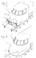
- reference T designates the front headstock of a high-speed railway vehicle, provided with an aerodynamic fairing C with two openings A formed in an inferior portion, through each of which a buffer end plate of a respective buffer 2 projects outwardly.
- each buffer 2 comprises, in a way generally known per se, a buffer casting 3 provided with a connecting flange 4 for the rigid fixing to the structure of the headstock T, and a hollow buffer stem 5 carrying the buffer end plate 1 and slidably supported by the buffer casting 3.
- Axial backing of the buffer stem 5 (and thus of the buffer end plate 1) relative to the buffer casting 3 enables, as is known, absorbtion of frontal impacts possibly transmitted during travelling by a railway carriage coupled ahead of the headstock T, or during manoeuvres of the vehicle.
- a conventional elastic dissipator system is interposed between the buffer stem 5 and the buffer casting 3, within the latter.
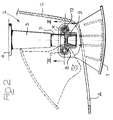
- the buffer end plate 1 is not connected rigidly to the free end of the buffer stem 5, but rotatably between an extended working position, shown in figure 1 and in continuous lines in figure 2, and a retracted or folded rest position, shown in dotted lines in figure 2 and in figure 4.
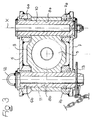
- the structure of the buffer end plate 1 incorporates internally an upper plate 6 and a lower plate 7 between which a support body 8, mounted in the teminal portion 9 of the buffer stem 5, is inserted.
- connection between the two plates 6, 7 of the buffer plate 1 and the support body 8 of the buffer stem 5 is performed, in the case of the shown example, by means of a pair of verticals studs 10, 11 placed side by side and inserted through corresponding holes 6a, 7a, 8a and 6b, 7b and 8b of the plates 6, 7 and of the body 8, respectively.
- the stud 10 is fixed, and the axis X thereof defines the pivot axis of the buffer plate 1 between the extended and the retracted positions.
- the stud 11 defines on the other hand a relasable latch, and to this purpose it is provided at its upper end with a grip eye 12 and at its lower end with a radial stop pin 13, which can be pulled out in order to allow extraction upwardly of said stud 11.
- the buffer plate 1 In the extended working position the buffer plate 1 is placed on the prolongation of the buffer stem 5, with the stud 11 inserted through the holes 6b, 7b of the two plates 6 and through the hole 8b of the support body 8, and is projecting in front of the fairing C of the headstock T through the corresponding opening A. In such a position the buffer plate is able to receive and transmit to the buffer 2 any possible front impact.
- the buffer plate 1 In the retracted position the buffer plate 1 is fully housed within the fairing C and the relative opening A can be advantegeously closed by applying a movable section S which completes the aerodynamic profile of the fairing C and is detachably secured thereto by any suitable means, such as screw locking members or the like.
- the buffer 2 is in any case able to protect the railway vehicle from possible accidental collisions, through the push applied through the fairing C to the end 9 of the buffer stem 5.
- the axis of rotation X of the buffer plate 1 could be placed differently from the vertical direction, i.e. could be oriented horizontally or even obliquely.
Landscapes
- Engineering & Computer Science (AREA)
- Mechanical Engineering (AREA)
- Vibration Dampers (AREA)
- Memory System Of A Hierarchy Structure (AREA)
- Automatic Cycles, And Cycles In General (AREA)
- Train Traffic Observation, Control, And Security (AREA)
- Maintenance And Inspection Apparatuses For Elevators (AREA)
- Platform Screen Doors And Railroad Systems (AREA)
- Braking Arrangements (AREA)
Claims (6)
- Puffer (2) für Schienenfahrzeuge, wobei der Puffer ein Puffergehäuse (3), das an einem Fahrwerksrahmen (T) des Fahrzeugs befestigt werden kann, sowie einen hohlen Pufferstempel (5) besitzt, der vom Puffergehäuse (3) verschiebbar aufgenommen wird und eine Pufferendplatte (1) trägt, dadurch gekennzeichnet, daß die Pufferendplatte (1) mit dem Pufferstempel (5) des Puffers (2) drehbar verbunden ist, so daß sie zwischen einer ausgefahrenen Arbeitsstellung und einer eingefahrenen Ruhestellung auslenkbar ist.
- Puffer gemäß Anspruch 1, dadurch gekennzeichnet, daß die Verbindung zwischen der Pufferendplatte (1) und dem Pufferstempel (5) ein Paar von Bolzen (10, 11) enthält, von denen einer die Drehachse (X) der Pufferplatte (1) zwischen der ausgefahrenen und der eingefahrenen Stellung bildet, und von denen der andere von einer freigebbaren Verriegelung (11) gebildet wird.
- Puffer gemäß Anspruch 2, dadurch gekennzeichnet, daß die Drehachse (X) der Pufferendplatte (1) vertikal ausgerichtet ist.
- Puffer gemäß irgendeinem der bisherigen Ansprüche, dadurch gekennzeichnet, daß der Puffer mit einer Servoeinrichtung versehen ist, um die Pufferendplatte (1) zwischen der ausgefahrenen und der eingefahrenen Stellung zu betätigen.
- Schienenfahrzeug, im besonderen ein Hochgeschwindigkeits-Schienenfahrzeug, dadurch gekennzeichnet, daß das Schienenfahrzeug mit einem Paar von Puffern (2) gemäß irgendeinem der bisherigen Ansprüche versehen ist, wobei die Puffer (2) an zumindest einem Fahrwerksrahmen (T) des Schienenfahrzeugs beabstandet befestigt sind.
- Schienenfahrzeug gemäß Anspruch 5, wobei der Fahrwerksrahmen (T) mit einer aerodynamischen Verkleidung (C) versehen ist, dadurch gekennzeichnet, daß die Verkleidung (C) vor jedem Puffer (2) mit einem bewegbaren Teil (S) ausgestattet ist, der so aufgebaut ist, daß er entfernt werden kann, so daß die Pufferendplatte (1) des Puffers (2) in der ausgefahrenen Arbeitsstellung nach außen vorspringen kann, und daß er wieder angebracht werden kann, wenn die Pufferplatte (1) in die eingefahrene Stellung innerhalb der Verkleidung (C) geschoben ist.
Applications Claiming Priority (2)
| Application Number | Priority Date | Filing Date | Title |
|---|---|---|---|
| ITTO921055 | 1992-12-30 | ||
| ITTO921055A IT1257962B (it) | 1992-12-30 | 1992-12-30 | Respingente per veicoli ferrotranviari e veicolo ferroviario ad alta velocita' provvisto di tale respingente. |
Publications (2)
| Publication Number | Publication Date |
|---|---|
| EP0605367A1 EP0605367A1 (de) | 1994-07-06 |
| EP0605367B1 true EP0605367B1 (de) | 1996-11-13 |
Family
ID=11410958
Family Applications (1)
| Application Number | Title | Priority Date | Filing Date |
|---|---|---|---|
| EP93830289A Expired - Lifetime EP0605367B1 (de) | 1992-12-30 | 1993-07-02 | Schienenfahrzeugpuffer und Hochgeschwindigkeits-Eisenbahnfahrzeug mit einem solchen Puffer |
Country Status (4)
| Country | Link |
|---|---|
| EP (1) | EP0605367B1 (de) |
| AT (1) | ATE145178T1 (de) |
| DE (1) | DE69305969D1 (de) |
| IT (1) | IT1257962B (de) |
Families Citing this family (3)
| Publication number | Priority date | Publication date | Assignee | Title |
|---|---|---|---|---|
| EP3053802B1 (de) * | 2015-02-06 | 2020-04-22 | ALSTOM Transport Technologies | Zugverband mit Crash-Absorbern, die deaktivierbar sind |
| DE102016114700B4 (de) * | 2016-08-09 | 2022-06-09 | Deutsches Zentrum für Luft- und Raumfahrt e.V. | Fahrzeug und Puffervorrichtung für ein Fahrzeug |
| DE102017102448A1 (de) | 2017-02-08 | 2018-08-09 | Voith Patent Gmbh | Knickgelenk-Verbindungseinrichtung und Kupplungsvorrichtung mit einer Kupplungsstange mit über eine Knickgelenk-Verbindungseinrichtung verbindbaren Kupplungsstangenteilen |
Family Cites Families (4)
| Publication number | Priority date | Publication date | Assignee | Title |
|---|---|---|---|---|
| DE409635C (de) * | 1925-02-10 | Paul Richter | Eisenbahnpuffer | |
| GB846429A (en) * | 1957-06-07 | 1960-08-31 | Bombrini Parodi Delfino S P A | Unit for transferring containers from one vehicle to another |
| GB909572A (en) * | 1958-10-03 | 1962-10-31 | Garringtons Ltd | Improvements in railway vehicle buffers |
| IT8721252A0 (it) * | 1987-07-10 | 1987-07-10 | Costamasnaga Spa | Carro ferroviario con testata mobile verticale. |
-
1992
- 1992-12-30 IT ITTO921055A patent/IT1257962B/it active IP Right Grant
-
1993
- 1993-07-02 AT AT93830289T patent/ATE145178T1/de active
- 1993-07-02 DE DE69305969T patent/DE69305969D1/de not_active Expired - Lifetime
- 1993-07-02 EP EP93830289A patent/EP0605367B1/de not_active Expired - Lifetime
Also Published As
| Publication number | Publication date |
|---|---|
| EP0605367A1 (de) | 1994-07-06 |
| DE69305969D1 (de) | 1996-12-19 |
| ATE145178T1 (de) | 1996-11-15 |
| IT1257962B (it) | 1996-02-19 |
| ITTO921055A1 (it) | 1994-06-30 |
| ITTO921055A0 (it) | 1992-12-30 |
Similar Documents
| Publication | Publication Date | Title |
|---|---|---|
| NO333865B1 (no) | Automatisk, sentral bufferkobling | |
| US5050817A (en) | Combined road and aircraft vehicle | |
| US8622003B2 (en) | Device for the on-demand sealing of an opening provided in the frontal region of a track-guided vehicle, a front nose module having such a device, and a track-guided vehicle having such a front nose module | |
| MX9401157A (es) | Carro de servicio y ensamble de cerrojo para el mismo. | |
| EP0605367B1 (de) | Schienenfahrzeugpuffer und Hochgeschwindigkeits-Eisenbahnfahrzeug mit einem solchen Puffer | |
| RU138839U1 (ru) | Сцепное устройство и рельсовое транспортное средство | |
| FR2439124A1 (fr) | Vehicule, en particulier voiture de tourisme | |
| CA2121872A1 (en) | Slackless Buff Gear Connection System | |
| SE502692C2 (sv) | Fordon för körning på såväl väg som järnvägsspår | |
| US5039033A (en) | Raisable landing gear | |
| EP0344394B1 (de) | Schienenfahrzeug | |
| ATE75111T1 (de) | Servicewagen. | |
| RU2218286C2 (ru) | Передняя секция железнодорожного вагона | |
| US2186505A (en) | Motor vehicle | |
| US4477097A (en) | Non-rigid motorcycle sidecar chassis with rigid lock device | |
| CN209426779U (zh) | 一种夹紧装置及轨道牵引车 | |
| CN109278790A (zh) | 一种夹紧装置及轨道牵引车 | |
| CN211032717U (zh) | 转向装置及具有其的车辆 | |
| CA2078719A1 (en) | Brake arrangement for a railroad gondola car | |
| PT1422118E (pt) | Veículo ferroviário, em particular uma automotora ligeira | |
| CN206476005U (zh) | 折叠收缩式车架及具有该折叠收缩式车架的卡丁车 | |
| SU948720A2 (ru) | Устройство дл закреплени механизма кантовани кузова вагона в розетке автосцепки | |
| GB2289615A (en) | Combined head and neck protection system | |
| CN2426823Y (zh) | 汽车用新型能量吸收式安全杠 | |
| JPH04129372U (ja) | 鉄道車両の連結装置 |
Legal Events
| Date | Code | Title | Description |
|---|---|---|---|
| PUAI | Public reference made under article 153(3) epc to a published international application that has entered the european phase |
Free format text: ORIGINAL CODE: 0009012 |
|
| AK | Designated contracting states |
Kind code of ref document: A1 Designated state(s): AT BE CH DE ES FR GB IT LI PT SE |
|
| 17P | Request for examination filed |
Effective date: 19941216 |
|
| GRAG | Despatch of communication of intention to grant |
Free format text: ORIGINAL CODE: EPIDOS AGRA |
|
| GRAH | Despatch of communication of intention to grant a patent |
Free format text: ORIGINAL CODE: EPIDOS IGRA |
|
| 17Q | First examination report despatched |
Effective date: 19951218 |
|
| RAP1 | Party data changed (applicant data changed or rights of an application transferred) |
Owner name: FIAT FERROVIARIA S.P.A. |
|
| GRAH | Despatch of communication of intention to grant a patent |
Free format text: ORIGINAL CODE: EPIDOS IGRA |
|
| GRAA | (expected) grant |
Free format text: ORIGINAL CODE: 0009210 |
|
| AK | Designated contracting states |
Kind code of ref document: B1 Designated state(s): AT BE CH DE ES FR GB IT LI PT SE |
|
| PG25 | Lapsed in a contracting state [announced via postgrant information from national office to epo] |
Ref country code: LI Effective date: 19961113 Ref country code: IT Free format text: LAPSE BECAUSE OF FAILURE TO SUBMIT A TRANSLATION OF THE DESCRIPTION OR TO PAY THE FEE WITHIN THE PRE;WARNING: LAPSES OF ITALIAN PATENTS WITH EFFECTIVE DATE BEFORE 2007 MAY HAVE OCCURRED AT ANY TIME BEFORE 2007. THE CORRECT EFFECTIVE DATE MAY BE DIFFERENT FROM THE ONE RECORDED.SCRIBED TIME-LIMIT Effective date: 19961113 Ref country code: FR Effective date: 19961113 Ref country code: ES Free format text: THE PATENT HAS BEEN ANNULLED BY A DECISION OF A NATIONAL AUTHORITY Effective date: 19961113 Ref country code: CH Effective date: 19961113 Ref country code: BE Effective date: 19961113 |
|
| REF | Corresponds to: |
Ref document number: 145178 Country of ref document: AT Date of ref document: 19961115 Kind code of ref document: T |
|
| REF | Corresponds to: |
Ref document number: 69305969 Country of ref document: DE Date of ref document: 19961219 |
|
| PG25 | Lapsed in a contracting state [announced via postgrant information from national office to epo] |
Ref country code: SE Effective date: 19970213 Ref country code: PT Effective date: 19970213 |
|
| PG25 | Lapsed in a contracting state [announced via postgrant information from national office to epo] |
Ref country code: DE Effective date: 19970214 |
|
| EN | Fr: translation not filed | ||
| REG | Reference to a national code |
Ref country code: CH Ref legal event code: PL |
|
| PG25 | Lapsed in a contracting state [announced via postgrant information from national office to epo] |
Ref country code: GB Free format text: LAPSE BECAUSE OF NON-PAYMENT OF DUE FEES Effective date: 19970702 |
|
| PGFP | Annual fee paid to national office [announced via postgrant information from national office to epo] |
Ref country code: AT Payment date: 19970724 Year of fee payment: 5 |
|
| PLBE | No opposition filed within time limit |
Free format text: ORIGINAL CODE: 0009261 |
|
| STAA | Information on the status of an ep patent application or granted ep patent |
Free format text: STATUS: NO OPPOSITION FILED WITHIN TIME LIMIT |
|
| 26N | No opposition filed | ||
| GBPC | Gb: european patent ceased through non-payment of renewal fee |
Effective date: 19970702 |
|
| PG25 | Lapsed in a contracting state [announced via postgrant information from national office to epo] |
Ref country code: AT Free format text: LAPSE BECAUSE OF NON-PAYMENT OF DUE FEES Effective date: 19980702 |