EP0603820B1 - Verfahren und Einrichtung zur Zeichenherstellung - Google Patents
Verfahren und Einrichtung zur Zeichenherstellung Download PDFInfo
- Publication number
- EP0603820B1 EP0603820B1 EP93120609A EP93120609A EP0603820B1 EP 0603820 B1 EP0603820 B1 EP 0603820B1 EP 93120609 A EP93120609 A EP 93120609A EP 93120609 A EP93120609 A EP 93120609A EP 0603820 B1 EP0603820 B1 EP 0603820B1
- Authority
- EP
- European Patent Office
- Prior art keywords
- predetermined value
- character
- area ratio
- solid
- lattice
- Prior art date
- Legal status (The legal status is an assumption and is not a legal conclusion. Google has not performed a legal analysis and makes no representation as to the accuracy of the status listed.)
- Expired - Lifetime
Links
Images


Classifications
-
- G—PHYSICS
- G06—COMPUTING; CALCULATING OR COUNTING
- G06F—ELECTRIC DIGITAL DATA PROCESSING
- G06F40/00—Handling natural language data
- G06F40/10—Text processing
- G06F40/103—Formatting, i.e. changing of presentation of documents
- G06F40/109—Font handling; Temporal or kinetic typography
-
- G—PHYSICS
- G06—COMPUTING; CALCULATING OR COUNTING
- G06K—GRAPHICAL DATA READING; PRESENTATION OF DATA; RECORD CARRIERS; HANDLING RECORD CARRIERS
- G06K15/00—Arrangements for producing a permanent visual presentation of the output data, e.g. computer output printers
- G06K15/02—Arrangements for producing a permanent visual presentation of the output data, e.g. computer output printers using printers
-
- G—PHYSICS
- G06—COMPUTING; CALCULATING OR COUNTING
- G06T—IMAGE DATA PROCESSING OR GENERATION, IN GENERAL
- G06T11/00—2D [Two Dimensional] image generation
- G06T11/20—Drawing from basic elements, e.g. lines or circles
- G06T11/203—Drawing of straight lines or curves
-
- G—PHYSICS
- G06—COMPUTING; CALCULATING OR COUNTING
- G06K—GRAPHICAL DATA READING; PRESENTATION OF DATA; RECORD CARRIERS; HANDLING RECORD CARRIERS
- G06K2215/00—Arrangements for producing a permanent visual presentation of the output data
- G06K2215/0002—Handling the output data
- G06K2215/002—Generic data access
- G06K2215/0028—Generic data access characterised by the format per se
-
- G—PHYSICS
- G06—COMPUTING; CALCULATING OR COUNTING
- G06K—GRAPHICAL DATA READING; PRESENTATION OF DATA; RECORD CARRIERS; HANDLING RECORD CARRIERS
- G06K2215/00—Arrangements for producing a permanent visual presentation of the output data
- G06K2215/0002—Handling the output data
- G06K2215/004—Generic data transformation
- G06K2215/0042—Rasterisation
Definitions
- the present invention relates to character output method and apparatus for generating a font pattern of a character to be displayed or printed.
- a hammer type printer of a large scale computer, a daisy wheel type printer of a personal computer, or the like is known.
- an impact printer of the dot matrix type, a thermal copy transfer printer, an ink jet printer, a laser beam printer of the electrophotographic type, or the like is known.
- the latter method has recently become a main stream because several kinds of character shapes (what are called fonts) can be selected without exchanging a print head and a figure can be also easily formed.
- a method to store a skeletal structure of the character
- a method to store the character as a binary image in a dot matrix form
- a method to store an outline of the character
- the dot font system is mainly used in case of displaying a middle or small character in a printer of a middle or low resolution.
- the vector font system is mainly used in a pen plotter.
- the outline font system is mainly used in a printer of a high resolution.
- the vector font system is a method of storing the skeletal structure of the character, there is a problem such that a character of a high quality cannot be expressed.
- the dot font system has a problem such that a number of dots are necessary to express a character of a high quality.
- the outline font system has a problem such that processes upon printing are complicated because the character outline is stored and the character is printed.
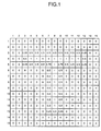
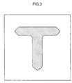
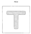
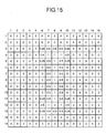
- Fig. 1 is an explanatory diagram showing a storing method of a character shape according to the first embodiment of the invention.
- a method of storing a character "T" is shown as an example. That is, a plane on which a character is printed is divided into square elements by a square lattice of (15 x 15).
- a numerical'value written in each element indicates an area ratio (ratio of the area to be printed to the area of each element).
- the values of the corners of both edges of a lateral stroke and the lower edges of a vertical stroke are set to 0.25
- an outline is set to 0.5
- the corners at which the outline crosses are set to 0.75
- the inside of the outline is set to 1.
- an area ratio function F(x, y) at a point (x, y) of each of the above elements is defined so as to coincide with the area ratio of the element at the center of each element.
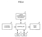
- Fig. 4 is a block constructional diagram of a dot matrix type printing apparatus according to the embodiment.
- a controller 1 When receiving a print command through an external interface 2, a controller 1 extracts the character shape data according to a character code from an ROM 3 or an RAM 4. Namely, the data expressing an area ratio in each element shown in Fig. 1 by eight bits has previously been stored as a character font in the ROM 3. Such character shape data is extracted from the ROM 3 or from the RAM 4 for registration of external characters.
- a linear interpolation processor 5 calculates the value of the area ratio function F corresponding to each print dot from the character shape data, thereby controlling so that a print head 6 prints the dots when F ⁇ 0.5 (G ⁇ 128).
- Fig. 5A shows partial elements (2 x 3) extracted from the elements (15 x 15) in the embodiment.
- the data In case of the edge data, the data must be supplemented in order to perform the bilinear interpolation. It is sufficient to previously store such supplementary data into the ROM 3 or RAM 4.
- Fig. 5B shows the result in the case where in order to actually output data on a dot unit basis, each element is divided on a unit basis of 2 x 2 (in this case, it is also possible to divide each element on a unit basis of 4 x 4, 16 x 16, or the like) and is bilinearly interpolated and the value (area ratio function F) of the central portion of each dot of a bit map memory (4 x 6) in the RAM 4 is calculated.
- Fig. 5A shows partial elements (2 x 3) extracted from the elements (15 x 15) in the embodiment.
- the data In case of the edge data, the data must be supplemented in order to perform the bilinear interpolation. It is sufficient to previously
- 5C shows the result in the case where the dots at the positions of F ⁇ 0.5 in the bit map memory (4 x 6) in the RAM 4 were turned on in order to print the dots.
- the resultant data is transferred to a print buffer (not shown) and an image corresponding to the data can be printed by the print head 6.
- a method of storing the area ratio function F is not limited to the above 8-bit fixed point system and an arbitrary bit length can be used in accordance with a necessary precision.
- another system such that the area ratio function F is divided into an exponential part and a mantissa part by using a floating point system and stored.
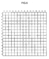
- Fig. 6 is an explanatory diagram showing a storing method of a character shape according to the second embodiment.
- a plane is divided into square elements by a square lattice of (15 x 15) in a manner similar to the first embodiment, the value of the area ratio is given by vertexes (lattice points) of the elements in the second embodiment.
- the area ratio at the lattice point indicated by a circle is equal to "1".
- the area ratios at the other lattice points are equal to "0".
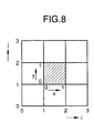
- a smooth outline can be obtained by using an interpolation polynomial of a high degree.
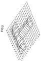
- an interpolation polynomial of a high degree For instance, as shown in Fig. 8, when the value of the area ratio function F(x, y) at the point (x, y) in the central element shown by a hatched region is interpolated by an Overhauser's piecewise cubic polynomial as a C1 class function, it is expressed as shown by the equation (1).
- E 0 (x) -0.5x + x 2 - 0.5x 3
- E 1 (x) 1 - 2.5x 2 + 1.5x 3
- E 2 (x) 0.5x + 2x 2 - 1.5x 3
- E 3 (x) -0.5x 2 + 0.5x 3
- the interpolation function it is not limited to the numerical equations (2) to (5) but it is also possible to use, for example, another C1 class piecewise quadrature polynomial, Lagrangean polynomial, spline function, or the like.
- the spline function a calculation amount upon reproduction can be reduced by storing the spline coefficients instead of the value of the area ratio itself.
- the area ratio function F is expressed by a C2 class function.
- the "spline” is not what is called a spline curve in which a dot train to express the outline are displayed by one parameter but denotes the result obtained by performing a 2-variable spline interpolation to the area ratio function F as a function of x and y.
- a preparation by the diffusion can be performed to the value of the area ratio function in order to further smoothly express the outline of the character.
- Fnew i,j F i,j + D(F i-l,j + F i+l,j + F i,j-l + F i,j+l - 4 x F i,j )
- D denotes a diffusion coefficient which was made dimensionless and is generally selected to a value of 0.25 or less in consideration of the stability of an explicit diffusion scheme.
- Fnew i,j obtained by the numerical equation (6) is set to the area ratio function F i,j and the numerical equation (6) can be used by only the necessary number of times.
- Such a diffusing process is also effective even in case of forming a font according to the invention by using a character font for a dot matrix printer as a fundamental font. This is because jaggies which are peculiar to the character font for the dot matrix printer are smoothed by the diffusing process.
- a difference equation other than the numerical equation (6) for instance, an implicit scheme shown by the numerical equation (8) or the like can be used.
- Fnew i,j F i,j + D(Fnew i-l,j + Fnew i+l,j +Fnew i,j-l + Fnew i,j+l - 4 x Fnew i,j )
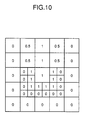
- Fig. 10 shows an example in the case where the element in the lowest portion of the vertical stroke of the character "T" was finely divided.
- Such an element can be further finely divided as necessary.
- Information indicating which element was finely divided is separately stored.
- the finely divided region by reducing the number of bits which express the area ratio function F(x, y), an excessive increase in memory capacity can be prevented. For instance, in the case where each element is expressed by eight bits, it is sufficient that the finely divided region is expressed by four bits.
- Figs. 12A and 12B a character of a thin stroke can be processed as shown in Fig. 12E. That is, Figs. 12A to 12E show an example in which a line that is thinner than the size of element is expressed by a difference (Fig. 12C to Fig. 12D) of two area ratio matrices.
- a triangular lattice or a hexagonal lattice can be also used in place of the orthogonal lattice.
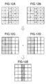
- Other lattices of various shapes or a combination thereof can be also used as shown in Figs. 13A to 13F.
- a lattice of a parallelogram shown in Fig. 13A is suitable in case of expressing an Italic character style. In this case, however, by storing the data of the type style without changing and by deforming the lattice upon reproduction, a character can be printed by an Italic character style.
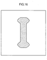
- Fig. 14 is a diagram showing a method of expressing a character "I" as a solid in the sixth embodiment of the invention.
- the shape of the character "I” is obtained.
- a length of vertical lateral rod continuously changes and various different kinds of type styles are obtained.
- a space region (0 ⁇ x ⁇ 15, 0 ⁇ y ⁇ 15, 0 ⁇ z ⁇ 15) including such a solid is divided into elements by a cubic lattice (unit length is equal to 1) of 15 x 15 x 15 and stored into a memory in a character generator in a manner such that a ratio of the volume which is occupied in each element to the element volume, namely, a volume ratio can be reconstructed.
- the value of the volume ratio is given at the vertex (lattice point or another point on the plane or side of the element or a combination thereof is also possible) of the element instead of the center of the element.
- a smooth outline can be obtained by using an interpolation polynomial of a high degree.
- the value of the volume ratio function F(x, y) at the point (x, y) in the central element (hatched portion) is interpolated by using the Overhauser's piecewise cubic polynomial as a C1 class function, it becomes as shown by the numerical equation (1).
- the volume ratio function is expressed by a C2 class function.
- the "spline" here is not what is called a spline curve such that a dot train expressing the outline are displayed by one parameter but indicates the result obtained by performing the 2-variable spline inter-polation to the volume ratio function F as a function of (x, y).
- a preparation by the diffusion can be also executed to the value of the volume ratio function in order to smoothly express the outline of the character.
- F i,j at the vertex (i, j)
- Fnew i,j can be also obtained from the numerical equation (6).
- D denotes the diffusion coefficient which was made dimensionless and is generally selected to a value of 0.25 or less in consideration of the stability of the explicit diffusion scheme.
- the Fnew i,j obtained by the numerical equation (6) is set to F i,j and the numerical equation (6) can be used a proper number of times.
- d denotes the distance as a target of the diffusion and is expressed as shown by the numerical equation (7) by using the diffusion coefficient D and the number n of diffusion processing times.
- Such a diffusing process is also effective to produce a type style by the method of the invention on the basis of the character type style for a dot matrix printer. This is because notches which are peculiar to the type style for the dot matrix printer are smoothed by the diffusing process.
- a difference equation other than the numerical equation (6) for example, an implicit scheme (numerical equation (8)) or the like can be also used. In this case, it is necessary to solve a matrix equation regarding F new .
- the diffusion in the xy plane has been considered in the numerical equations (6) and (8), it is also possible to include the diffusion in the z direction.
- the diffusion coefficient in the z direction is not necessarily the same as the diffusion coefficient in the xy plane.
- the position of the solid surface can be also stored in addition to a method of using the volume ratio function as in the sixth and seventh embodiments.
- a curve surface by a piecewise polynomial by using the points to control the solid shape or the feature points on the solid surface.
- a method such as spline curved surface, Bezier curved surface, Overhauser curved surface, or the like which is used in the CAD or computer graphics.
- Figs. 20A to 20D show various kinds of solids to express three kinds of type styles of the character "I” and their intermediate type styles.
- a portion to express an oblique character style of the character "I” is added onto the solid of Fig. 14.
- a portion to express a bold character style of the character "I” is added onto the solid of Fig. 14.
- a portion to express a character style in which a vertical length of the character "I" is short is added onto the solid of Fig. 14.
- the shape of Fig. 20D although a type style similar to the shape of Fig. 20B is expressed, the type style changes nonlinearly (like a curve) and the shape is different from the shape of Fig. 20B.
- three or more kinds of type styles and their intermediate type styles can be expressed by one solid.
- the solid corresponding to the region to be printed has been considered so far, on the contrarily, it is also possible to consider a solid corresponding to the region which is not printed, namely, the portion in which the solid that is expressed in each of Figs. 20A to 20D is eliminated from the space region. Further, it is also possible to consider a hollow solid and to express the character by the hollow portion.
- the cut plane is not necessarily set to a horizontal plane. By cutting the solid at an angle that is inclined in the front/back direction or right/left direction, a character such that the type style changes in the vertical or lateral direction of the character can be also reproduced. Further, the cut plane can be also set to a curved plane.
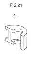
- the solid is not cut at planes which are parallel with each other but is cut at a plane including the z axis.
- Fig. 21 shows a solid to express the character "I" in various kinds of type styles in the case according to such a method.
- the controller 1 reads out the data from the character font ROM 3, thereby obtaining the plane data of the cut plane of the solid, that is, the character shape data.
- the font data produced has been transferred to the print buffer (not shown) and printed by the print head 6.
- the print buffer not shown
- the plane region to which a character is output is divided into lattice-like elements (orthogonal lattice, triangular lattice, hexagonal lattice, etc.).
- the area ratio of the area to be output in each element to the element is previously stored.
- the portion in which the area ratio is larger than the first predetermined value and is smaller than the second predetermined value is regarded as a distribution such that the area ratio continues on the basis of the values of the area ratios of such an element and its peripheral elements.
- the portion in which the area ratio is equal to or larger than the third predetermined value is output. Therefore, the outline of the character is expressed by the area ratio of the area to be output in each of the lattice-like elements to the element area.
- a character of a high quality can be output or a character can be also freely enlarged or reduced.
- the memory means for storing the area ratio to the element area formed like a lattice since there are provided the arithmetic operating means for calculating the area ratio corresponding to the output dots, the output device to output the character, and the control means for generating an output command to the output device when the area ratio is equal to or larger than a predetermined value. Therefore, the above character output method can be simply and easily realized.
- the character shapes of a plurality of kinds of type styles are stored in a form of solid shape, a plurality of character type styles and their intermediate type styles can be stored and reproduced by a smaller memory capacity and a simple arithmetic operation.
- a plane region to which characters are output is divided into lattice-like elements (orthogonal lattice, triangular lattice, hexagonal lattice, etc.).
- lattice-like elements orthogonal lattice, triangular lattice, hexagonal lattice, etc.
- an area ratio of the area to be output to the element is previously stored.
- the portion in the element in which the area ratio is larger than the first predetermined value and is smaller than the second predetermined value is regarded as a distribution of the continuous area ratio on the basis of the values of the area ratios of such an element and the elements therearound.
- the portion in which the area ratio is equal to or larger than a third predetermined value is output.
Claims (44)
- Zeichenausgabeverfahren mit den Schritten:Aufteilen eines Ebenenbereichs, in den ein Zeichen ausgegeben wird, in gitterartige Elemente und vorheriges Speichern eines Flächenverhältnisses einer auszugebenden Fläche für jedes Element; undAusgeben keines Abschnitts eines Elements, für das das Flächenverhältnis gleich einem ersten vorbestimmten Wert ist,vollständiges Ausgeben eines Elements, für das das Flächenverhältnis gleich einem zweiten vorbestimmten Wert ist, der größer als der erste vorbestimmte Wert ist,bei jedem Element, für das das Flächenverhältnis größer als der erste vorbestimmte Wert ist und kleiner als der zweite vorbestimmte Wert ist, eine kontinuierliche Flächenverhältnisverteilung auf der Grundlage der Werte der Flächenverhältnisse eines derartigen Elements und seiner Peripherieelemente bestimmen, undAusgeben des Abschnitts des Elements, in dem das Flächenverhältnis gleich einem dritten vorbestimmten Wert oder größer ist.
- Verfahren nach Anspruch 1, wobei der erste vorbestimmte Wert das Flächenverhältnis von "0" angibt und der zweite vorbestimmte Wert das Flächenverhältnis von "1" angibt.
- Verfahren nach Anspruch 1 oder 2, wobei das Gitter, das für die Elemente verwendet wird, entweder ein orthogonales Gitter, ein dreieckiges Gitter oder ein sechseckiges Gitter oder eine Kombination davon ist.
- Verfahren nach einem der Ansprüche 1 bis 3, wobei das gitterartige Element in eine Vielzahl von Elementen fein aufgeteilt wird und das Flächenverhältnis für jedes der fein aufgeteilten Elemente vorher gespeichert wird.
- Verfahren nach einem der Ansprüche 1 bis 4, wobei der gespeicherte Wert des Flächenverhältnisses entweder dem Mittelpunkt des Elements, einem Punkt an einer Seite des Elements, einem Punkt an dem Gitter oder einer Kombination davon zugewiesen wird.
- Verfahren nach einem der Ansprüche 1 bis 5, wobei das Flächenverhältnis verbreitungsverarbeitet wird, bevor die kontinuierliche Flächenverhältnisverteilung bestimmt wird.
- Verfahren nach einem der Ansprüche 1 bis 6, wobei das Flächenverhältnis durch ein vorbestimmtes Interpolationsverfahren interpoliert wird, der Abschnitt des Elements, in dem das Flächenverhältnis gleich dem dritten vorbestimmten Wert oder größer ist, berechnet wird und der Abschnitt, in dem das Flächenverhältnis gleich dem dritten vorbestimmten Wert oder größer ist, gedruckt wird.
- Verfahren nach Anspruch 7, wobei das vorbestimmte Interpolationsverfahren entweder ein lineares Interpolationsverfahren, ein kubisches Interpolationsverfahren der C1-Klasse, ein Lagrangesches Interpolationsverfahren oder ein Spline-Interpolationsverfahren ist.
- Verfahren nach einem der Ansprüche 1 bis 7, wobei die Positionen an der Seite des Elements, bei denen das Flächenverhältnis gleich dem dritten vorbestimmten Wert oder größer ist, erhalten werden, ein Umriß des Zeichens erhalten wird, indem die Positionen verbunden werden, und der Abschnitt, in dem das Flächenverhältnis gleich dem dritten vorbestimmten Wert oder größer ist, auf der Grundlage des Umrisses gedruckt wird.
- Verfahren nach Anspruch 9, wobei in dem Fall, daß das Element einen Kantenabschnitt eines Zeichenstrichs umfaßt, ein Umriß des Zeichens erhalten wird, indem der Umriß des Zeichens des angrenzenden Elements des Elements extrapoliert wird.
- Zeichenausgabevorrichtung mit:einer Speichereinrichtung zum Aufteilen eines Ebenenbereichs, in den ein Zeichen ausgegeben wird, in gitterartige Elemente und vorherigen Speichern eines Flächenverhältnisses einer auszugebenden Fläche für jedes Element; undeiner Ausgabeeinrichtung, die dazu eingerichtet istkeinen Abschnitt eines Elements auszugeben, für das das Flächenverhältnis gleich einem ersten vorbestimmten Wert ist,ein Element vollständig auszugeben, für das das Flächenverhältnis gleich einem zweiten vorbestimmten Wert ist, der größer als der erste vorbestimmte Wert ist,bei jedem Element, für das das Flächenverhältnis größer als der erste vorbestimmte Wert ist und kleiner als der zweite vorbestimmte Wert ist, eine kontinuierliche Flächenverhältnisverteilung auf der Grundlage der Werte der Flächenverhältnisse eines derartigen Elements und seiner Peripherieelemente zu bestimmen, undden Abschnitt des Elements auszugeben, in dem das Flächenverhältnis gleich einem dritten vorbestimmten Wert oder größer ist.
- Vorrichtung nach Anspruch 11, wobei der erste vorbestimmte Wert das Flächenverhältnis von "0" angibt und der zweite vorbestimmte Wert das Flächenverhältnis von "1" angibt.
- Vorrichtung nach Anspruch 11 oder 12, wobei das Gitter, das für die Elemente verwendet wird, entweder ein orthogonales Gitter, ein dreieckiges Gitter oder ein sechseckiges Gitter oder eine Kombination davon ist.
- Vorrichtung nach einem der Ansprüche 11 bis 13, wobei das gitterartige Element in eine Vielzahl von Elementen fein aufgeteilt wird und das Flächenverhältnis für jedes der fein aufgeteilten Elemente vorher gespeichert wird.
- Vorrichtung nach einem der Ansprüche 11 bis 14, wobei der gespeicherte Wert des Flächenverhältnisses entweder dem Mittelpunkt des Elements, einem Punkt an einer Seite des Elements, einem Punkt an dem Gitter oder einer Kombination davon zugewiesen wird.
- Vorrichtung nach einem der Ansprüche 11 bis 15, wobei das Flächenverhältnis verbreitungsverarbeitet wird, bevor die kontinuierliche Flächenverhältnisverteilung bestimmt wird.
- Vorrichtung nach einem der Ansprüche 11 bis 16, wobei das Flächenverhältnis durch ein vorbestimmtes Interpolationsverfahren interpoliert wird, der Abschnitt des Elements, in dem das Flächenverhältnis gleich dem dritten vorbestimmten Wert oder größer ist, berechnet wird und der Abschnitt, in dem das Flächenverhältnis gleich dem dritten vorbestimmten Wert oder größer ist, gedruckt wird.
- Vorrichtung nach Anspruch 17, wobei das vorbestimmte Interpolationsverfahren entweder ein lineares Interpolationsverfahren, ein kubisches Interpolationsverfahren der C1-Klasse, ein Lagrangesches Interpolationsverfahren oder ein Spline-Interpolationsverfahren ist.
- Vorrichtung nach einem der Ansprüche 11 bis 17, wobei die Positionen an der Seite des Elements, bei denen das Flächenverhältnis gleich dem dritten vorbestimmten Wert oder größer ist, erhalten werden, ein Umriß des Zeichens erhalten wird, indem derartige Positionen verbunden werden, und der Abschnitt, in dem das Flächenverhältnis gleich dem dritten vorbestimmten Wert oder größer ist, auf der Grundlage des Umrisses gedruckt wird.
- Vorrichtung nach Anspruch 19, wobei in dem Fall, daß das Element einen Kantenabschnitt eines Zeichenstrichs umfaßt, der Umriß des Zeichens erhalten wird, indem der Umriß des Zeichens des an das Element angrenzenden Elements extrapoliert wird.
- Zeichenausgabeverfahren mit den Schritten:Aufteilen eines Raumbereichs einschließlich eines Festkörpers in Elemente durch ein in einem Speicher gespeichertes kubisches Gitter und vorheriges Speichern eines Volumenverhältnisses, das ein Verhältnis des in dem Element belegten Volumens zu dem Volumen des Elements ist, für jedes Element;Zerschneiden des Festkörpers bei einer vorbestimmten Ebene und Zuordnen eines entsprechenden Volumenverhältnisses zu jedem der Elemente des Raumbereichs schneidenden planaren Elemente;Ausgeben keines Abschnitts eines planaren Elements, für das das Volumenverhältnis gleich einem ersten vorbestimmten Wert ist;vollständiges Ausgeben eines planaren Elements, für das das Volumenverhältnis gleich einem zweiten vorbestimmten Wert ist, der größer als der erste vorbestimmte Wert ist;bei jedem planaren Element, für das das Volumenverhältnis größer als der erste vorbestimmte Wert ist und kleiner als der zweite vorbestimmte Wert ist, eine kontinuierliche Volumenverhältnisverteilung auf der Grundlage der Werte der Volumenverhältnisse eines derartigen planaren Elements und seiner planaren Peripherieelemente bestimmen; undAusgeben des Abschnitts des planaren Elements, in dem das Volumenverhältnis gleich einem dritten vorbestimmten Wert oder größer ist.
- Verfahren nach Anspruch 21, wobei durch ein Zerschneiden des Festkörpers bei Ebenen, die parallel zueinander sind, eine Vielzahl von Schriftarten ausgedrückt wird.
- Verfahren nach Anspruch 21, wobei der Festkörper sich derart kontinuierlich ändert, daß eine Vielzahl von Schriftarten durch den Festkörper gespeichert wird und die Zeichenform bei der Schneideebene sich ebenfalls kontinuierlich ändert.
- Verfahren nach Anspruch 21, wobei ein Raum einschließlich des Festkörpers durch ein Gitter in eine Vielzahl von Elementen aufgeteilt wird und die Form des Festkörpers in Form eines ein Verhältnis des Volumens, das durch den Festkörper in jedem Element belegt wird, zu dem Elementvolumen angebenden Volumenverhältnisses gespeichert wird.
- Verfahren nach Anspruch 24, wobei ein Teil des Elemente aufteilenden Gitters fein aufgeteilt ist.
- Verfahren nach Anspruch 24, wobei der Wert des Volumenverhältnisses entweder dem Mittelpunkt des Elements, einem Punkt an der Schneideebene, einem Punkt an einer Seite des Elements, einem Punkt an dem Gitter oder einer Kombination davon zugewiesen wird und gespeichert wird.
- Verfahren nach Anspruch 24, wobei ein Verbreitungsprozeß bei dem Wert des Volumenverhältnisses ausgeführt wird, bevor die kontinuierliche Volumenverhältnisverteilung bestimmt wird.
- Verfahren nach Anspruch 24, wobei das Volumenverhältnis durch ein Interpolationsverfahren von entweder einer linearen Interpolation, einer kubischen Interpolation der C1-Klasse, einer Lagrangeschen Interpolation oder einer Spline-Interpolation interpoliert wird und der Festkörper durch die Interpolation ausgedrückt wird.
- Verfahren nach Anspruch 24, wobei Orte an der Seite des Elements, bei denen das Volumenverhältnis gleich einem vorbestimmten Wert ist, erhalten werden, ein Umriß des Festkörpers erhalten wird, indem derartige Orte verbunden werden, und der Zeichenformabschnitt, in dem das Volumenverhältnis gleich dem dritten vorbestimmten Wert oder größer ist, auf der Grundlage des Umrisses ausgegeben wird.
- Verfahren nach Anspruch 24, wobei bei dem einen Kantenabschnitt eines Zeichenstrichs umfassenden Element der Zeichenumriß erhalten wird, indem der Zeichenumriß bei dem angrenzenden Element des Elements extrapoliert wird.
- Verfahren nach Anspruch 21, wobei die Form der Oberfläche des Festkörpers als eine Form des Festkörpers gespeichert wird.
- Verfahren nach Anspruch 31, wobei die Form der Oberfläche des Festkörpers durch eine gekrümmte Oberfläche gemäß einem stückweisen Polynom ausgedrückt wird.
- Zeichenausgabevorrichtung mit:einer Speichereinrichtung zum Aufteilen eines Raumbereichs einschließlich eines Festkörpers in Elemente durch ein gespeichertes kubisches Gitter und vorherigen Speichern eines Volumenverhältnisses, das ein Verhältnis des in dem Element belegten Volumens zu dem Volumen des Elements ist, für jedes Element;einer Bildverarbeitungseinrichtung zum Zerschneiden des Festkörpers bei einer vorbestimmten Ebene und Zuordnen eines entsprechenden Volumenverhältnisses zu jedem der Elemente des Raumbereichs schneidenden planaren Elemente;einer Ausgabeeinrichtung, die dazu eingerichtet istkeinen Abschnitt eines planaren Elements auszugeben, für das das Volumenverhältnis gleich einem ersten vorbestimmten Wert ist;ein planares Element vollständig auszugeben, für das das Volumenverhältnis gleich einem zweiten vorbestimmten Wert ist, der größer als der erste vorbestimmte Wert ist;bei jedem planaren Element, für das das Volumenverhältnis größer als der erste vorbestimmte Wert ist und kleiner als der zweite vorbestimmte Wert ist, eine kontinuierliche Volumenverhältnisverteilung auf der Grundlage der Werte der Volumenverhältnisse eines derartigen planaren Elements und seiner planaren Peripherieelemente zu bestimmen; undden Abschnitt des planaren Elements auszugeben, in dem das Volumenverhältnis gleich einem dritten vorbestimmten Wert oder größer ist.
- Vorrichtung nach Anspruch 33, wobei durch ein Zerschneiden des Festkörpers bei Ebenen, die parallel zueinander sind, eine Vielzahl von Schriftarten ausgedrückt wird.
- Vorrichtung nach Anspruch 33, wobei der Festkörper sich derart kontinuierlich ändert, daß eine Vielzahl von Schriftarten durch den Festkörper gespeichert wird und die Zeichenform bei der Schneideebene sich ebenfalls kontinuierlich ändert.
- Vorrichtung nach Anspruch 33, wobei ein Raum einschließlich des Festkörpers durch ein Gitter in eine Vielzahl von Elementen aufgeteilt wird und die Form des Festkörpers in Form eines ein Verhältnis des Volumens, das durch den Festkörper in jedem Element belegt wird, zu dem Elementvolumen angebenden Volumenverhältnisses gespeichert wird.
- Vorrichtung nach Anspruch 36, wobei ein Teil des Elemente aufteilenden Gitters fein aufgeteilt ist.
- Vorrichtung nach Anspruch 36, wobei der Wert des Volumenverhältnisses entweder dem Mittelpunkt des Elements, einem Punkt an der Schneideebene, einem Punkt an der Seite des Elements, einem Punkt an dem Gitter oder einer Kombination davon zugewiesen wird.
- Vorrichtung nach Anspruch 36, wobei ein Verbreitungsprozeß bei dem Wert des Volumenverhältnisses ausgeführt wird, bevor die kontinuierliche Volumenverhältnisverteilung bestimmt wird.
- Vorrichtung nach Anspruch 36, wobei das Volumenverhältnis durch ein Interpolationsverfahren von entweder einer linearen Interpolation, einer kubischen Interpolation der C1-Klasse, einer Lagrangeschen Interpolation oder einer Spline-Interpolation interpoliert wird und der Festkörper durch die Interpolation ausgedrückt wird.
- Vorrichtung nach Anspruch 36, wobei Orte an der Seite des Elements, bei denen das Volumenverhältnis auf einen vorbestimmten Wert eingestellt ist, erhalten werden, ein Umriß des Festkörpers erhalten wird, indem derartige Orte verbunden werden, und der Zeichenformabschnitt, in dem das Volumenverhältnis gleich dem dritten vorbestimmten Wert oder größer ist, auf der Grundlage des Umrisses ausgegeben wird.
- Vorrichtung nach Anspruch 36, wobei bei dem einen Kantenabschnitt eines Zeichenstrichs umfassenden Element der Zeichenumriß erhalten wird, indem der Zeichenumriß bei dem angrenzenden Element eines derartigen Elements extrapoliert wird.
- Vorrichtung nach Anspruch 33, wobei die Form der Oberfläche des Festkörpers als eine Form des Festkörpers gespeichert wird.
- Vorrichtung nach Anspruch 43, wobei die Oberflächenform des Festkörpers durch eine gekrümmte Oberfläche gemäß einem stückweisen Polynom ausgedrückt wird.
Applications Claiming Priority (6)
| Application Number | Priority Date | Filing Date | Title |
|---|---|---|---|
| JP4356702A JP3035418B2 (ja) | 1992-12-22 | 1992-12-22 | 文字印字方法とその印字装置 |
| JP356702/92 | 1992-12-22 | ||
| JP35670292 | 1992-12-22 | ||
| JP16140893 | 1993-06-30 | ||
| JP161408/93 | 1993-06-30 | ||
| JP5161408A JP2919712B2 (ja) | 1993-06-30 | 1993-06-30 | 文字発生方法および装置 |
Publications (3)
| Publication Number | Publication Date |
|---|---|
| EP0603820A2 EP0603820A2 (de) | 1994-06-29 |
| EP0603820A3 EP0603820A3 (de) | 1995-08-30 |
| EP0603820B1 true EP0603820B1 (de) | 2002-05-22 |
Family
ID=26487568
Family Applications (1)
| Application Number | Title | Priority Date | Filing Date |
|---|---|---|---|
| EP93120609A Expired - Lifetime EP0603820B1 (de) | 1992-12-22 | 1993-12-21 | Verfahren und Einrichtung zur Zeichenherstellung |
Country Status (3)
| Country | Link |
|---|---|
| US (1) | US5850488A (de) |
| EP (1) | EP0603820B1 (de) |
| DE (1) | DE69331943D1 (de) |
Families Citing this family (9)
| Publication number | Priority date | Publication date | Assignee | Title |
|---|---|---|---|---|
| US7412360B2 (en) * | 2000-09-19 | 2008-08-12 | Technion Research & Development Foundation Ltd. | Method and apparatus for shape deformation and placement |
| US7153601B2 (en) | 2002-10-29 | 2006-12-26 | Hewlett-Packard Development Company, L.P. | Fuel cell with embedded current collector |
| US7256786B2 (en) * | 2004-05-28 | 2007-08-14 | Microsoft Corporation | Appropriately rendering a graphical object when a corresponding outline has exact or inexact control points |
| US8253742B2 (en) * | 2004-05-28 | 2012-08-28 | Microsoft Corporation | Rendering stroke pairs for graphical objects |
| US7292249B2 (en) * | 2004-05-28 | 2007-11-06 | Microsoft Corporation | Appropriately rendering a graphical object when a corresponding outline has excessive control points |
| US7785216B2 (en) | 2007-08-27 | 2010-08-31 | Acushnet Company | Golf balls including mechanically hybridized layers and methods of making same |
| JP2010056672A (ja) * | 2008-08-26 | 2010-03-11 | Oki Data Corp | 画像処理装置 |
| CN102739873B (zh) * | 2012-07-13 | 2017-01-18 | 上海触乐信息科技有限公司 | 便携式终端设备滑行操作辅助信息输入控制功能的系统及方法 |
| CN110941944B (zh) * | 2019-09-30 | 2023-04-25 | 中国重型机械研究院股份公司 | 一种将任意字体字符转化成喷印点阵的方法 |
Family Cites Families (10)
| Publication number | Priority date | Publication date | Assignee | Title |
|---|---|---|---|---|
| JPS59214382A (ja) * | 1983-05-19 | 1984-12-04 | Canon Inc | カラ−画像処理装置 |
| JPS60152942A (ja) * | 1984-01-23 | 1985-08-12 | Toshiba Corp | Nmr―ctスキャン計画装置 |
| IE852259L (en) * | 1985-09-13 | 1987-03-13 | Scottish & Newcastle Breweries | A method and apparatus for constructing, storing and¹displaying characters |
| IL80364A (en) * | 1986-10-20 | 1990-03-19 | Elscint Ltd | Three dimensional image construction using binary space interpolation |
| JPH03199061A (ja) * | 1989-12-27 | 1991-08-30 | Xerox Corp | フォントを傾斜させる方法 |
| US5339171A (en) * | 1990-04-24 | 1994-08-16 | Ricoh Company, Ltd. | Image processing apparatus especially suitable for producing smooth-edged output multi-level tone data having fewer levels than input multi-level tone data |
| US5287209A (en) * | 1990-10-09 | 1994-02-15 | Matsushita Electric Industrial Co., Ltd. | Image forming device for enhancing tone reproduction by changing dot size |
| US5337167A (en) * | 1991-04-03 | 1994-08-09 | Matsushita Electric Industrial Co., Ltd. | Halftone image forming apparatus including density based dot enlargement |
| JPH05143742A (ja) * | 1991-11-20 | 1993-06-11 | Ricoh Co Ltd | ベクトル画像描画装置 |
| US5258854A (en) * | 1991-12-06 | 1993-11-02 | Xerox Corporation | Converting between write-white, write-black and neutral bitmaps |
-
1993
- 1993-12-21 DE DE69331943T patent/DE69331943D1/de not_active Expired - Lifetime
- 1993-12-21 EP EP93120609A patent/EP0603820B1/de not_active Expired - Lifetime
-
1996
- 1996-01-16 US US08/585,709 patent/US5850488A/en not_active Expired - Fee Related
Also Published As
| Publication number | Publication date |
|---|---|
| EP0603820A3 (de) | 1995-08-30 |
| DE69331943D1 (de) | 2002-06-27 |
| EP0603820A2 (de) | 1994-06-29 |
| US5850488A (en) | 1998-12-15 |
Similar Documents
| Publication | Publication Date | Title |
|---|---|---|
| US5719595A (en) | Method and apparauts for generating a text image on a display with anti-aliasing effect | |
| US5381521A (en) | System and method of rendering curves | |
| EP0786757B1 (de) | Kontrastregelung für Antialiasing | |
| US4907282A (en) | Method and apparatus for constructing, storing and displaying characters | |
| JPH06266847A (ja) | ラスタ化されたオブジェクトを表示する方法および装置 | |
| EP0603820B1 (de) | Verfahren und Einrichtung zur Zeichenherstellung | |
| JPH08106276A (ja) | スクリーン上でのテキスト表示方法 | |
| EP0592770B1 (de) | Verfahren zum Ausfüllen der Bildpunkte innerhalb eines Polygons | |
| US6614432B1 (en) | Image rendering technique | |
| US5489920A (en) | Method for determining the optimum angle for displaying a line on raster output devices | |
| JPH05204363A (ja) | ドットマトリクス装置における輪郭字体文字生成のための高速垂直走査−変換・充填方法及びその装置 | |
| US5898439A (en) | Method and apparatus for drawing characters which draws curved segments based on approximate points | |
| JPH05143742A (ja) | ベクトル画像描画装置 | |
| JP2919712B2 (ja) | 文字発生方法および装置 | |
| JPH0813554B2 (ja) | 情報処理装置 | |
| JP3035418B2 (ja) | 文字印字方法とその印字装置 | |
| US7170528B1 (en) | Fast glyph rendering for vector based fonts | |
| US5134687A (en) | Method for converting image data into dot data | |
| KR940003701B1 (ko) | 컴퓨터를 사용한 문자도형 발생방법 | |
| JPH07120427B2 (ja) | グラフイツクス処理システム | |
| JPH0823741B2 (ja) | ベクトル文字もしくはベクトル図形の処理方法 | |
| JP3351093B2 (ja) | 画像処理方法およびその装置 | |
| JPH0668247A (ja) | ディジタル画像データ変倍方法および装置 | |
| JP2538631B2 (ja) | ベクトル文字の処理方法 | |
| JPH09146519A (ja) | キャラクタ合成装置 |
Legal Events
| Date | Code | Title | Description |
|---|---|---|---|
| PUAI | Public reference made under article 153(3) epc to a published international application that has entered the european phase |
Free format text: ORIGINAL CODE: 0009012 |
|
| AK | Designated contracting states |
Kind code of ref document: A2 Designated state(s): DE FR GB |
|
| PUAL | Search report despatched |
Free format text: ORIGINAL CODE: 0009013 |
|
| AK | Designated contracting states |
Kind code of ref document: A3 Designated state(s): DE FR GB |
|
| 17P | Request for examination filed |
Effective date: 19960115 |
|
| 17Q | First examination report despatched |
Effective date: 19991108 |
|
| RIC1 | Information provided on ipc code assigned before grant |
Free format text: 7G 06T 11/20 A, 7G 06K 15/02 B |
|
| GRAG | Despatch of communication of intention to grant |
Free format text: ORIGINAL CODE: EPIDOS AGRA |
|
| GRAG | Despatch of communication of intention to grant |
Free format text: ORIGINAL CODE: EPIDOS AGRA |
|
| GRAH | Despatch of communication of intention to grant a patent |
Free format text: ORIGINAL CODE: EPIDOS IGRA |
|
| GRAH | Despatch of communication of intention to grant a patent |
Free format text: ORIGINAL CODE: EPIDOS IGRA |
|
| GRAA | (expected) grant |
Free format text: ORIGINAL CODE: 0009210 |
|
| PG25 | Lapsed in a contracting state [announced via postgrant information from national office to epo] |
Ref country code: FR Free format text: LAPSE BECAUSE OF FAILURE TO SUBMIT A TRANSLATION OF THE DESCRIPTION OR TO PAY THE FEE WITHIN THE PRESCRIBED TIME-LIMIT Effective date: 20020522 |
|
| REG | Reference to a national code |
Ref country code: GB Ref legal event code: FG4D |
|
| REF | Corresponds to: |
Ref document number: 69331943 Country of ref document: DE Date of ref document: 20020627 |
|
| PG25 | Lapsed in a contracting state [announced via postgrant information from national office to epo] |
Ref country code: DE Free format text: LAPSE BECAUSE OF FAILURE TO SUBMIT A TRANSLATION OF THE DESCRIPTION OR TO PAY THE FEE WITHIN THE PRESCRIBED TIME-LIMIT Effective date: 20020823 |
|
| EN | Fr: translation not filed | ||
| PLBE | No opposition filed within time limit |
Free format text: ORIGINAL CODE: 0009261 |
|
| STAA | Information on the status of an ep patent application or granted ep patent |
Free format text: STATUS: NO OPPOSITION FILED WITHIN TIME LIMIT |
|
| 26N | No opposition filed |
Effective date: 20030225 |
|
| PGFP | Annual fee paid to national office [announced via postgrant information from national office to epo] |
Ref country code: GB Payment date: 20051221 Year of fee payment: 13 |
|
| GBPC | Gb: european patent ceased through non-payment of renewal fee |
Effective date: 20061221 |
|
| PG25 | Lapsed in a contracting state [announced via postgrant information from national office to epo] |
Ref country code: GB Free format text: LAPSE BECAUSE OF NON-PAYMENT OF DUE FEES Effective date: 20061221 |