EP0603582A1 - Photographisches Silberhalogenidmaterial mit einer magnetischen Aufzeichnungsschicht - Google Patents
Photographisches Silberhalogenidmaterial mit einer magnetischen Aufzeichnungsschicht Download PDFInfo
- Publication number
- EP0603582A1 EP0603582A1 EP93119026A EP93119026A EP0603582A1 EP 0603582 A1 EP0603582 A1 EP 0603582A1 EP 93119026 A EP93119026 A EP 93119026A EP 93119026 A EP93119026 A EP 93119026A EP 0603582 A1 EP0603582 A1 EP 0603582A1
- Authority
- EP
- European Patent Office
- Prior art keywords
- magnetic
- silver halide
- photographic material
- halide photographic
- magnetic recording
- Prior art date
- Legal status (The legal status is an assumption and is not a legal conclusion. Google has not performed a legal analysis and makes no representation as to the accuracy of the status listed.)
- Granted
Links
Images


Classifications
-
- G—PHYSICS
- G03—PHOTOGRAPHY; CINEMATOGRAPHY; ANALOGOUS TECHNIQUES USING WAVES OTHER THAN OPTICAL WAVES; ELECTROGRAPHY; HOLOGRAPHY
- G03C—PHOTOSENSITIVE MATERIALS FOR PHOTOGRAPHIC PURPOSES; PHOTOGRAPHIC PROCESSES, e.g. CINE, X-RAY, COLOUR, STEREO-PHOTOGRAPHIC PROCESSES; AUXILIARY PROCESSES IN PHOTOGRAPHY
- G03C5/00—Photographic processes or agents therefor; Regeneration of such processing agents
- G03C5/12—Cinematrographic processes of taking pictures or printing
- G03C5/14—Cinematrographic processes of taking pictures or printing combined with sound-recording
-
- G—PHYSICS
- G03—PHOTOGRAPHY; CINEMATOGRAPHY; ANALOGOUS TECHNIQUES USING WAVES OTHER THAN OPTICAL WAVES; ELECTROGRAPHY; HOLOGRAPHY
- G03C—PHOTOSENSITIVE MATERIALS FOR PHOTOGRAPHIC PURPOSES; PHOTOGRAPHIC PROCESSES, e.g. CINE, X-RAY, COLOUR, STEREO-PHOTOGRAPHIC PROCESSES; AUXILIARY PROCESSES IN PHOTOGRAPHY
- G03C11/00—Auxiliary processes in photography
- G03C11/02—Marking or applying text
-
- G—PHYSICS
- G03—PHOTOGRAPHY; CINEMATOGRAPHY; ANALOGOUS TECHNIQUES USING WAVES OTHER THAN OPTICAL WAVES; ELECTROGRAPHY; HOLOGRAPHY
- G03C—PHOTOSENSITIVE MATERIALS FOR PHOTOGRAPHIC PURPOSES; PHOTOGRAPHIC PROCESSES, e.g. CINE, X-RAY, COLOUR, STEREO-PHOTOGRAPHIC PROCESSES; AUXILIARY PROCESSES IN PHOTOGRAPHY
- G03C3/00—Packages of films for inserting into cameras, e.g. roll-films, film-packs; Wrapping materials for light-sensitive plates, films or papers, e.g. materials characterised by the use of special dyes, printing inks, adhesives
-
- G—PHYSICS
- G11—INFORMATION STORAGE
- G11B—INFORMATION STORAGE BASED ON RELATIVE MOVEMENT BETWEEN RECORD CARRIER AND TRANSDUCER
- G11B5/00—Recording by magnetisation or demagnetisation of a record carrier; Reproducing by magnetic means; Record carriers therefor
- G11B5/62—Record carriers characterised by the selection of the material
- G11B5/633—Record carriers characterised by the selection of the material of cinematographic films or slides with integral magnetic track
-
- G—PHYSICS
- G11—INFORMATION STORAGE
- G11B—INFORMATION STORAGE BASED ON RELATIVE MOVEMENT BETWEEN RECORD CARRIER AND TRANSDUCER
- G11B5/00—Recording by magnetisation or demagnetisation of a record carrier; Reproducing by magnetic means; Record carriers therefor
- G11B5/62—Record carriers characterised by the selection of the material
- G11B5/68—Record carriers characterised by the selection of the material comprising one or more layers of magnetisable material homogeneously mixed with a bonding agent
- G11B5/70—Record carriers characterised by the selection of the material comprising one or more layers of magnetisable material homogeneously mixed with a bonding agent on a base layer
- G11B5/702—Record carriers characterised by the selection of the material comprising one or more layers of magnetisable material homogeneously mixed with a bonding agent on a base layer characterised by the bonding agent
- G11B5/7028—Additives, e.g. crosslinking agents
-
- G—PHYSICS
- G11—INFORMATION STORAGE
- G11B—INFORMATION STORAGE BASED ON RELATIVE MOVEMENT BETWEEN RECORD CARRIER AND TRANSDUCER
- G11B5/00—Recording by magnetisation or demagnetisation of a record carrier; Reproducing by magnetic means; Record carriers therefor
- G11B5/62—Record carriers characterised by the selection of the material
- G11B5/68—Record carriers characterised by the selection of the material comprising one or more layers of magnetisable material homogeneously mixed with a bonding agent
- G11B5/70—Record carriers characterised by the selection of the material comprising one or more layers of magnetisable material homogeneously mixed with a bonding agent on a base layer
- G11B5/712—Record carriers characterised by the selection of the material comprising one or more layers of magnetisable material homogeneously mixed with a bonding agent on a base layer characterised by the surface treatment or coating of magnetic particles
-
- G—PHYSICS
- G03—PHOTOGRAPHY; CINEMATOGRAPHY; ANALOGOUS TECHNIQUES USING WAVES OTHER THAN OPTICAL WAVES; ELECTROGRAPHY; HOLOGRAPHY
- G03C—PHOTOSENSITIVE MATERIALS FOR PHOTOGRAPHIC PURPOSES; PHOTOGRAPHIC PROCESSES, e.g. CINE, X-RAY, COLOUR, STEREO-PHOTOGRAPHIC PROCESSES; AUXILIARY PROCESSES IN PHOTOGRAPHY
- G03C2200/00—Details
- G03C2200/10—Advanced photographic system
Definitions
- the present invention relates to a magnetic material and, in particular, to a silver halide photographic material (hereinafter referred to as "a photographic material” or “a photographic film”) including a magnetic recording layer containing a magnetic material.
- a photographic material or "a photographic film”
- the magnetic recording layer has improved transparency and the magnetic material dispersed in the magnetic recording layer has improved stability.
- Magnetic recording is an important and widely applicable recording means.
- Examples of magnetic recording media include video tape, audio tape, computer floppy discs, magnetic cards and the like. These magnetic recording media have different uses and are utilized in different ways. However, they all have a magnetic recording layer on a support.
- a ferromagnetic material is dispersed in a binder to form a coating solution which is thinly coated on the support.
- Analogue signals such as voice or music analogue signals, or computer digital signals are magnetically recorded on the magnetic recording layer as continuous minute magnets using a magnetic head.
- the magnetic recording layer must dependably record and reproduce the information of the original signals as much as possible.
- the magnetic recording and reproducing characteristics of the magnetic recording layer greatly depend upon the magnetic property of the magnetic material in the magnetic recording layer. In addition, these characteristics also greatly depend upon the dispersibility of the magnetic material in a binder present in the magnetic recording layer.
- the arrangement of the magnetic material and coagulated solids of the magnetic material in the magnetic recording layer as well as the ability of the binder for adsorbing to magnetic materials and the size of the secondary coagulated solids of the magnetic material, all influence the magnetic characteristics of the magnetic recording layer.
- the arrangement of the magnetic material and the coagulated solids of the magnetic material in the magnetic recording layer 15 influenced by the dispersibility of the magnetic material in the binder.
- One method of producing a photographic material having a magnetic recording layer includes dispersing a magnetic material, such as an acicular magnetic ferric oxide ( ⁇ -Fe2O3) or an acicular chromium oxide (CrO2), a solvent and other conventional additives in a binder using a mixing and dispersing machine (for example, a kneader, sand mill or the like).
- a mixing and dispersing machine for example, a kneader, sand mill or the like.
- the resultant dispersion is filtered to produce a coating solution dispersed.
- the coating solution dispersed is coated on a support and oriented in a magnetic field.
- preparing a coating solution dispersed by dispersing a magnetic material in a binder in the above described manner is usually not satisfactory.
- the resulting coating solution dispersed often coagulates in a short period of time, forming coarse grains therein. Accordingly, the preparation of a stable and fine dispersion of a magnetic material is extremely difficult.
- JP-B-42-4539 and JP-B-57-6576 have been made to apply a magnetic recording layer to a photographic film.
- JP-B as used herein means an "examined Japanese patent publication”.
- Conventional photographic films may have optical information written thereon (for example, the date), but cannot have any other information (for example, picture-taking conditions, objects, number of prints, trimming information, etc.). If a magnetic recording layer is combined with a photographic film, the film may advantageously include such information. If a magnetic recording layer is provided on a photographic film, it is essential that the magnetic recording layer does not reduce the photographic properties of the film, and it is necessary that the magnetic recording layer have sufficient magnetic characteristics in the film.
- the transparency of the film may be reduced due to the presence of the magnetic layer. This may be a severe problem with regard to the photographic property of the material. Moreover, if the magnetic material in the magnetic recording layer aggregates into coarse grains, the graininess of the film may be worsened which results in reduction of the photographic property of the film.
- Conventional methods for forming a magnetic recording layer include the use of a large amount of a magnetic material dispersed in a small amount of a binder, which results in a coating solution dispersed having high viscosity. This is necessary to form a stable coating solution dispersed that could be stored.
- the concentration of the magnetic material in the coating solution dispersed must be low and the amount of the binder therein must also be reduced.
- reducing the amount of the magnetic material causes the magnetic material to aggregate in the coating solution dispersed and form solids therein. The solids reduce worsen the photographic properties of the photographic film.
- an object of the present invention is to provide a magnetic material having an improved dispersion stability in a coating solution dispersed containing the magnetic material.
- Another object of the present invention is to provide a magnetic material capable of forming a magnetic recording layer on a photographic support, the magnetic recording layer having excellent transparency.
- Further object of the present invention is to provide a magnetic photographic film having excellent magnetic characteristics.
- a silver halide photographic material in accordance with the present invention having one or more silver halide emulsion layers located on one or more surfaces of a support.
- the photographic material includes one or more magnetic recording layers, each layer having a coercive force of at least 400 Oe.
- the magnetic recording layer or layers each contain from 10 to 300 mg/m2 of a granular magnetic material, the magnetic grains of which have a surface area of from 2 to 100 m2/g and a mean grain size of from 0.01 to 0.8 ⁇ m.
- the surfaces of the magnetic grains are treated with 1 to 200% by weight, based upon the weight of the magnetic grains, of one or both of a silane coupling agent represented by formula (I) and a titanium coupling agent of the following formula (II).
- a silane coupling agent represented by formula (I) represented by formula (I) and a titanium coupling agent of the following formula (II).
- (X1) n1 -Si-(R1) 4-n1 (I) (X2) n2 -Ti-(R2) 4-n2 (II) wherein X1 and X2 each represents a halogen atom, or a substituted or unsubstituted alkoxy group having from 1 to 20 carbon atoms; R1 and R2 each represents a substituted or unsubstituted alkyl, alkenyl or aryl group having from 1 to 45 carbon atoms; and n1 and n2 each represent an integer of from 1 to 3.
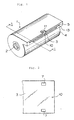
- Fig. 1 is a perspective view of a photographic film cartridge in accordance with the present invention.
- Fig. 2 is a plan view of the tip of the photographic film partially shown in Fig. 1.
- Fig. 3 is a cross-sectional view of the cartridge (i.e., the patrone) shown in Fig. 1 taken along lines 3 - 3 of Fig. 1.
- Fig. 4 is a partially cut-away view of the cartridge of Fig. 1.
- Fig. 5 is a plan view of a magnetic recording track layer of a backing layer of a photographic film in accordance with the present invention.
- Fig. 5(a) is a cross-sectional view of the photographic film in accordance with the present invention.
- 1 is a photographic film cartridge
- 2 is a spool
- 3 is a photographic film
- 4 is a cartridge body
- 5 is a film-drawing mouth
- 7 is a perforation
- 8 is a projection
- 9 is a convex part
- 10 is a hole
- 11 is a notch
- 12 is a film-drawing guide
- 12 is a step
- 14 is an emulsion layer
- 15 is a support
- 16 is a transparent magnetic layer
- 17 comprises an antistatic layer, a scratch-resistant layer and a lubricant layer
- 18 is one frame
- 19 is a perforation
- t-0, t-1, t-2, t-3, t00, t29 and f00 to f29 each is a magnetic recording track.
- FIG. 1 shown a preferred photographic film patrone or cartridge 1 in accordance with the invention and including a spool 2 having a photographic film 3 (including a hole 10 and a perforation 7) wound thereon, and a cartridge body 4.
- Cartridge 1 may have any suitable shape. Preferably, the shape of cartridge 1 is suitable for use with commercial cameras.
- a cartridge body 1 suitable for use with a so-called 35 mm camera is shown in Fig. 1.
- Cartridge body 4 includes a film-drawing mouth (i.e., a film take out mouth) 5, a projection 8 and a convex part 9.
- Notch 11 is provided in mouth 5, a film-drawing path 12 (i.e., a film take out path 12) and step 13 is located inside cartridge body 4 for forming a film drawing guide.
- one frame 18 of film 3 includes perforation 19 and magnetic recording tracks t-0, t-1, t-2, t-3, t-00, t-29 and f00 to f29, the magnetic tracks being provided as a transparent magnetic layer 16 provided on one side of a support 15 having a light-sensitive emulsion layer 14 provided on another side of support 15.
- Antistatic layer 17, which also functions as a scratch-resistant layer and a lubricant layer, may be provided on magnetic layer 16.
- the magnetic grains include, for example, ferromagnetic iron oxide grains, Co-containing ferromagnetic iron oxide grains, ferromagnetic chromium dioxide grains, ferromagnetic metal grains, ferromagnetic alloy grains, magnetite grains, Co-containing magnetite grains and barium ferrite grains.
- suitable ferromagnetic alloy grains include those having a metal content of at least 75% by weight, in which at least 80% by weight of the metal content includes one or more ferromagnetic metals or alloys (e.g., Fe, Co, Ni, Fe-Co, Fe-Ni, Co-Ni, Co-Fe-Ni) and at least 20% by weight of the same includes another component or components (e.g., Al, Si, S, Sc, Ti, V, Cr, Mn, Cu, Zn, Y, Mo, Rh, Pd, Ag, Sn, Sb, B, Ba, Ta, W, Re, Au, Hg, Pb, P, La, Ce, Pr, Nd, Te, Bi).
- the ferromagnetic metal may contain a small amount of water, hydroxides or oxides.
- ferromagnetic powders Methods for preparing such ferromagnetic powders are known, and ferromagnetic substances suitable for use in the present invention may be prepared by conventional methods.
- the ferromagnetic grains used in the present invention may have any suitable shape and size.
- the shape may be, for example, acicular, ellipsoidal, spherical, cubic or tabular, acicular and cubic shapes are especially preferred in view of their electromagnetic characteristic.
- the crystallite size of spherical grains, if used in the present invention, is preferably from 0.01 ⁇ m to 0.8 ⁇ m, more preferably from 0.02 ⁇ m to 0.5 ⁇ m.
- Acicular grains if used in the present invention, preferably have a size whereby the length in the long axis is preferably from 0.01 to 0.8 ⁇ m, the length in short axis is preferably from 0.005 to 0.4 ⁇ m and the ratio of the long axis to the short axis is preferably from 100/1 to 2/1. More preferably, the length in the long axis is from 0.04 to 0.4 ⁇ m, the length in the short axis is from 0.01 to 0.1 ⁇ m, and the ratio of the length in the long axis to the length in the short axis is from 100/1 to 3/1.
- the maximum length of the grains is preferably from 0.05 to 0.8 ⁇ m and the thickness thereof is preferably from 0.005 to 0.4 ⁇ m. More preferably, the maximum length of them is from 0.05 to 0.4 ⁇ m and the thickness thereof is from 0.05 to 0.2 ⁇ m.
- the ratio of the maximum length to the thickness of the grains is preferably from 2 to 100, more preferably from 4 to 30.
- X1 and X2 each preferably represents a halogen atom, or a substituted or unsubstituted alkoxy group having from 1 to 10 carbon atoms, more preferably a Cl atom or -OR3 (wherein R3 is an alkyl group having up to 8 carbon atoms).
- X1 and X2 each represents a Cl atom, a methyloxy group, an ethyloxy group, a propyloxy group, an isopropyloxy group, a butyloxy group, a cyclohexyloxy group, a chloroethyloxy group, a benzyloxy group or an ethylenedioxy group.
- X1 and X2 each represents a Cl atom, a methyloxy group, an ethyloxy group, an isopropyloxy group or a butyloxy group.
- the silane coupling agent and titanium coupling agent (sometimes herein referred to collectively as "the coupling agents") of the present invention may be applied to the magnetic grains by any conventional method so as to modify the surfaces of the grains, whereby the stability of a coating solution containing the thus treated magnetic material is improved.
- the coupling agents may be applied to the magnetic grains by a direct treating method or by an integral blending method.
- the direct method includes dry methods, slurry methods and spray methods.
- the magnetic material as treated by the direct treating method is added to a binder, and is excellent for use in the present invention as the surfaces of the magnetic grains are surely modified by the coupling agents applied thereto.
- the drying method includes uniformly dispersing the magnetic grains in an aqueous alcoholic solution, an organic solvent solution or an aqueous solution of the silane coupling agent and then drying the grains.
- a Henschel mixer, a super mixer, a ready-mixer, a V-shaped blender, an open kneader or the like mixing machine is preferred.
- the use of an oven kneader is more preferred.
- the magnetic grains be blended in an open kneader along with a small amount of water or a water-containing organic solvent and the coupling agent. The water is then removed from the resulting mixture and the mixture is further ground and finely dispersed.
- the slurry method includes adding the coupling agents to a slurry of the magnetic grains.
- the grains may be formed into a slurry during the production of the same. This method is advantageous since the addition of the coupling agents may be effected during the process of producing the magnetic grains.
- the spray method includes adding the coupling agents to the magnetic grains during the step of drying the magnetic material. This method is advantageous since the addition of the coupling agents may be effected during the process of producing the magnetic grains, but it may be disadvantageous since the treatment of the grains with the coupling agents may be uneven.
- the integral blending method includes adding both the coupling agents and the magnetic grains to a binder under sufficient stirring. This method is simple.
- the binder may be a conventional thermoplastic resin, thermosetting resin, radiation-hardening resin, reactive resin, acid-decomposing polymer, alkali-decomposing polymer or biodegradable polymer, natural polymers (e.g., a cellulose derivative, or a saccharide derivative) and mixtures thereof, which have heretofore been used as a binder for conventional magnetic recording media. It will be understood that a blend of thermoplastic resins, for example, may be used as the binder.
- resins having a glass transition temperature (Tg) of from -40°C to 300°C, more preferably -40°C to 200°C, and having a weight average molecular weight of from 2,000 to 1,000,000, more preferably from 5,000 to 300,000, are preferred.
- thermoplastic resins include: vinyl copolymers, such as vinyl chloride-vinyl acetate copolymer, copolymers of vinyl chloride, vinyl acetate, vinyl alcohol, maleic acid and/or acrylic acid, vinyl chloride-vinylidene chloride copolymer, vinyl chloride-acrylonitrile copolymer, and ethylene-vinyl acetate copolymer; cellulose derivatives, such as nitrocellulose, cellulose diacetate, cellulose triacetate, cellulose acetate propionate, and cellulose acetate butyrate resins; acrylic resins; polyvinyl acetal resins; polyvinyl butyral resins; polyester polyurethane resins; polyether polyurethane resins; polycarbonate polyurethane resins; polyester resins; polyether resins; polyamide resins; amino resins; styrene-butadiene resins; butadiene-acrylonitrile resins and other rubber resins; as well as silicone resins and fluor
- thermosetting resins and reactive resins may have an extremely high molecular weight when heated, and they include, for example, phenolic resins, phenoxy resins, epoxy resins, hardening polyurethane resins, urea resins, melamine resins, alkyd resins, silicone resins, acrylic reactive resins, epoxy-polyamide resins, nitrocellulose-melamine resins, mixtures of high molecular polyester resins and isocyanate prepolymers, urea-formaldehyde resins, low molecular weight glycol/high molecular weight diol/polyisocyanate mixtures, polyamine resins, and mixtures thereof.
- Suitable radiation-hardening resins include those prepared by introducing carbon-carbon unsaturated bond-having groups, as radiation-hardening functional groups, into the above-mentioned thermoplastic resins.
- Preferred functional group include an acryloyl group and a methacryloyl group.
- Suitable cellulose derivatives include diacetyl cellulose, triacetyl cellulose, acetyldibutyl acetate, tripropionyl acetate and didodecyl acetate.
- Polar groups may be included in the above-mentioned binders.
- suitable polar groups which may be used in the present invention include an epoxy group, a CO2M group, an OH group, an NR2 group, an NR3X group, a SO3M group, an OSO3M group, a PO3M2 group and an OPO3M2 group where M is a hydrogen atom, an alkali metal or ammonium, and when one group has more than one M group, they may be same or different; and R is a hydrogen atom or an alkyl group (preferably having 1 to 12 carbon atoms); X represents a halogen atom.
- Binders containing such polar groups are preferred because the dispersibility of the magnetic material of the present invention therein is good, and the durability of the magnetic material therein is also good. Further, the use of the fluorine-containing oligomer surfactants of the present invention further improves the dispersibility and the durability.
- the amount of the polar groups in the binder may be generally from 10 ⁇ 7 to 10 ⁇ 3 equivalents, preferably from 10 ⁇ 6 to 10 ⁇ 4 equivalents, to gram of the binder.
- binders may be used singly or in combinations (including of different kinds of binders) thereof.
- Conventional epoxy, aziridine or isocyanate crosslinking agents and/or radiation-hardening vinyl monomers may be added to the binders for purposes of hardening the binders.
- Suitable isocyanate crosslinking agents include polyisocyanate compounds having at least 2 isocyanate groups, including, for example, isocyanates such as tolylene-diisocyanate, 4,4'-diphenylmethane-diisocyanate, hexamethylene-diisocyanate, xylylene-diisocyanate, naphthylene-1,5-diisocyanate, o-toluidine-diisocyanate, isophorone-diisocyanate and triphenylmethane-diisocyanate; reaction products of the foregoing isocyanates and poly-alcohols (e.g., the reaction product of 3 mols of toluene-isocyanate and one mol of trimethylolpropane); and poly-isocyanates formed by condensation of the foregoing isocyanates.
- isocyanates such as tolylene-diisocyanate, 4,4'-dipheny
- Suitable radiation-hardening vinyl monomers which may be included in the binder include compounds which are polymerizable by radiation and which contain one or more carbon-carbon unsaturated bonds in the molecule. They include, for example, (meth)acrylates, (meth)acrylamides, allyl compounds, vinyl esters, vinyl-heterocyclic compounds, N-vinyl compounds, styrenes, (meth)acrylic acids, crotonic acid, itaconic acid and olefinic acids.
- the radiation-hardening vinyl monomers include two or more (meth)acryloyl groups, for example, polyethylene glycol (meth)acrylates, such as diethylene glycol di(meth)acrylate and triethylene glycol di(meth)acrylate, as well as trimethylol propane tri(meth)acrylate, pentaerythritol tetra(meth)acrylate, dipentaerythritol penta(meth)acrylate, dipentaerythritol hexa(meth)acrylate, and and reaction products of polyisocyanates and hydroxy(meth)acrylate compounds.
- polyethylene glycol (meth)acrylates such as diethylene glycol di(meth)acrylate and triethylene glycol di(meth)acrylate
- trimethylol propane tri(meth)acrylate pentaerythritol tetra(meth)acrylate
- dipentaerythritol penta(meth)acrylate dipentaeryth
- crosslinking agents are preferably combined with the binder in an amount of from 5 to 45% by weight based upon the weight of the binder.
- a hydrophilic binder may be utilized in the magnetic recording layer of the present invention.
- Suitable hydrophilic binders are described in Research Disclosure No. 17643, page 26 and No. 18716, page 651 may be used, and include, for example, water-soluble polymers, cellulose esters, latex polymers, and water-soluble polyesters.
- Suitable water-soluble polymers include, for example, gelatin, gelatin derivatives, casein, agar, sodium alginate, starch, polyvinyl alcohol, polyacrylic acid copolymers, and maleic anhydride copolymers.
- Suitable cellulose esters include, for example, carboxymethyl cellulose and hydroxyethyl cellulose.
- Suitable latex polymers include, for example, vinyl chloride-containing copolymers, vinylidene chloride-containing copolymers, acrylate-containing copolymers, vinyl acetate-containing copolymers, and butadiene-containing copolymers. Of the foregoing, gelatin is most preferred.
- Gelatin may be classified, depending upon the process used to produce it, into a so-called "alkali-processed” (or lime-processed) gelatin which is produced by dipping gelatin in an alkaline bath prior to extraction of the gelatin, acid-processed gelatin which is produced by dipping gelatin in an acid bath, a double-processed gelatin which is produced using both of the treatment discussed above, and enzyme-processed gelatin. Any type of gelatin may be used in the present invention.
- the gelatin for use in the present invention may be combination-used with or may partially be substituted by cellulose derivatives, such as colloidal albumin, casein, carboxymethyl cellulose or hydroxyethyl cellulose, saccharide derivatives, such as agar, sodium alginate, starch derivatives or dextran, synthetic hydrophilic colloids, such as polyvinyl alcohol, poly-N-vinylpyrrolidone, polyacrylic acid polymers, polyacrylamide or their derivatives or partial hydrolysates, or gelatin derivatives.
- cellulose derivatives such as colloidal albumin, casein, carboxymethyl cellulose or hydroxyethyl cellulose
- saccharide derivatives such as agar, sodium alginate, starch derivatives or dextran
- synthetic hydrophilic colloids such as polyvinyl alcohol, poly-N-vinylpyrrolidone, polyacrylic acid polymers, polyacrylamide or their derivatives or partial hydrolysates, or gelatin derivatives.
- the magnetic recording layer contains gelatin and is hardened.
- suitable hardening agents include, for example, aldehyde compounds, such as formaldehyde and glutaraldehyde; ketone compounds, such as diacetyl and cyclopentanedione; bis(2-chloroethylurea); 2-hydroxy-4,6-dichloro-1,3,5-triazine, and other reactive halogen-containing compounds described in U.S.
- Patents 3,288,775 and 2,732,303 the disclosures of which are herein incorporated by reference and British Patents 974,723 and 1,167,207; divinylsulfone; 5-acetyl-1,3-diacryloylhexahydro-1,3,5-triazine, and other reactive olefin compounds as described in U.S. Patents 3,635,718 and 3,232,763, the disclosures of which are herein incorporated by reference and British Patent 994,869; N-hydroxymethylphthalimide, and other N-methylol compounds as described in U.S. Patents 2,732,316 and 2,586,168, the disclosures of which are herein incorporated by reference; isocyanates, as described in U.S.
- Patent 3,103,437 the disclosures of which are-herein incorporated by reference; aziridine compounds, as described in U.S. Patents 3,017,280 and 2,983,611, the disclosures of which are herein incorporated by reference; acid derivatives, as described in U.S. Patents 2,725,294 and 2,725,295, the disclosures of which are herein incorporated by reference; epoxy compounds, as described in U.S. Patent 3,091,537, the disclosures of which are herein incorporated by reference; and halogenocarboxyaldehydes, such as mucochloric acid.
- Suitable inorganic compound hardening agents include chromium alum, zirconium sulfate, and other carboxyl-reactive hardening agents as described in JP-B-56-12853, JP-B-58-32699, Belgian Patent 825,726, JP-A-60-225148, JP-A-51-126125, JP-B-58-50699, JP-A-52-54427, and U.S. Patent 3,321,313.
- the amount of the hardening agent present in the magnetic recording layer is preferably from 0.01 to 30% by weight, more preferably from 0.05 to 20% by weight, based upon the weight of dry gelatin.
- the thickness of the magnetic recording layer is preferably from 0.1 ⁇ m to 10 ⁇ m, more preferably from 0.2 ⁇ m to 5 ⁇ m, and most preferably from 0.3 ⁇ m to 3 ⁇ m.
- the weight ratio of the magnetic grains to the binder in the magnetic recording layer is preferably from 1/100 to 40/100, more preferably from 5/100 to 30/100.
- the magnetic recording layer containing the magnetic material in accordance with the present invention is provided in a silver halide photographic material, i.e., a photographic film.
- the magnetic recording layer may be formed wholly or in a stripewise manner on a back surface of a photographic support by coating or printing. It is preferred that a binder solution containing magnetic grains dispersed therein and a binder solution for forming a support be co-spread wholly or in a stripewise manner on a substrate to form a support having a magnetic recording layer thereon.
- the composition of the binder containing the magnetic grains and the composition of the binder for forming the support may be different from each other, but preferably they are the same.
- any suitable method may be used to coat the magnetic recording layer on the support including, for example, air doctor coating, blade coating, air knife coating, squeeze coating, impregnation coating, reverse roll coating, transfer roll coating, gravure coating, kiss coating, cast coating, spray coating, dip coating, bar coating and extrusion coating methods.
- air doctor coating blade coating
- air knife coating squeeze coating
- impregnation coating reverse roll coating
- transfer roll coating gravure coating
- kiss coating cast coating
- spray coating dip coating
- bar coating bar coating and extrusion coating methods.
- Other methods will be apparent to one skilled in the art. Detailed explanations of the coating methods are described in, for example, Coating Engineering, pp. 253 to 277 (published by Asakura Shoten on March 20, 1971).
- the magnetic recording layer After the magnetic recording layer has been coated on a support, it is oriented and, optionally, the magnetic material in the layer is immediately dried. Then, the thus formed magnetic recording layer is dried.
- the velocity of the support is generally from 2 to 500 m/min (preferably from 20 to 200 m/min), and the drying temperature is within the range of from 20 to 250°C (preferably from 50 to 200°C).
- the surface of the magnetic recording layer may be smoothed. In this way, the magnetic recording layer of the present invention is formed. Formation of a magnetic recording layer is described in, for example, JP-B-40-23625, JP-B-39-28368 and U.S. Patent 3,473,960, the disclosures of which are herein incorporated by reference. Reference may also be had to the method disclosed in JP-B-41-13181 which is considered to be a basic and important technique in this technical field.
- the magnetic recording layer of the present invention may function to improve the lubricating property of the photographic material in accordance with the present invention, as well as prevent curling of the material, reduce static charge from accumulating therein and reduce sticking of the material.
- additional layers may be formed over the magnetic recording layer to perform such functions.
- a protective layer may be provided adjacent to the magnetic recording layer so as to improve the scratch resistance of the magnetic recording layer.
- inorganic or organic fine grains such as fine grains of SiO2, SnO2, Al2O3, TiO2, crosslinked polymethyl methacrylate, barium carbonate, silicon
- the back surface of a support having the magnetic recording layer thereon may be calendered so as to improve the smoothness of the support to thereby improve the S/N ratio of magnetic signals applied thereto.
- Photographic layers are preferably coated on the surface of the support opposite to the calendered back surface, as will be discussed below.
- any suitable support may be employed in producing the photographic material of the present invention.
- the support may be any conventional plastic film.
- the film is a cellulose derivative, e.g., diacetyl-acetate, triacetyl-acetate, propionyl-acetate, butanoyl-acetate or acetylpropionyl-acetate; a polyamide; a polycarbonate as described in U.S.
- Patent 3,023,101 the disclosures of which are herein incorporated by reference, a polyester as described in JP-B 48-40414, e.g., polyethylene terephthalate, poly-1,4-cyclohexanedimethylene terephthalate, polyethylene naphthalate; a polystyrene; a polypropylene; a polyethylene; a polysulfone; a polyarylate and a polyether imide. More preferably, the support is triacetyl cellulose or polyesters such a polyethylene tetrephthalate, polyethylene naphthalate or polyarylate.
- the film comprising the support may contain a compound having polar groups, e.g., an epoxy group, a COO2M group, a OH group, a NR2 group, a NR3X group, a SO3M group, a OSO3M group, a PO3M2 group, or a OP3M2 group, wherein M is a H atom, an alkali metal or ammonium, and R is a H atom or an alkyl group having from 1 to 20 carbon atoms.
- polar groups e.g., an epoxy group, a COO2M group, a OH group, a NR2 group, a NR3X group, a SO3M group, a OSO3M group, a PO3M2 group, or a OP3M2 group, wherein M is a H atom, an alkali metal or ammonium, and R is a H atom or an alkyl group having from 1 to 20 carbon atoms.
- the support of the invention is polyethylene terephthalate, polyethylene naphthalate or polyarylate.
- the supports are heat-treated at a temperature up to the Tg of the support so as to reduce their propensity to curl.
- polyethylene having a Tg of about 120°C may be heat-treated at a temperature of up to 119°C for a period of from 0.2 to 48 hours, more preferably at 115°C for 24 hours.
- the support may be first heated to a temperature higher than the Tg thereof and then gradually cooled to a temperature of about the Tg thereof.
- the heat treatment in accordance with the process is especially preferred to obtain the high efficiency for the heat treatment of the supports.
- Polyethylene terephthalate may be first heated to a temperature falling within the range of from 130°C to 200°C and then cooled to 125°C and thereafter further cooled gradually to 100°C over a period of 40 minutes. In this way, the time needed for the heat treatment of polyethylene terephthalate may be shortened extremely.
- the thickness of the support in accordance with the present invention may be preferably from 60 ⁇ m to 300 ⁇ m, more preferably from 70 ⁇ m to 200 ⁇ m. If the thickness is less than 60 ⁇ m, the support may be easily broken when rapid tensile power is imparted thereto. On the other hand, if the thickness of the support is more than 300 ⁇ m, the photographic film would fail to contact a magnetic head when it is housed in a film cartridge for a long period of time, although the film strength is increased. In particular, when such a film having a support thickness of greater than 300 ⁇ m is housed in an automatic feeding cartridge, such as that described in U.S. Patent 4,913,368, the disclosures of which are herein incorporated by reference, the magnetic characteristic of the film deteriorates.
- the support of the photographic material in accordance with the present invention may contain a plasticizer so as to be soft and flexible.
- a plasticizer such as triphenyl phosphate, biphenyl diphenyl phosphate or dimethylethyl phosphate, may be utilized in cellulose ester supports.
- the surface of the support may be previously activated by chemical treatment, mechanical treatment, corona discharging treatment, flame treatment, ultraviolet treatment, high frequency treatment, glow discharging treatment, active plasma treatment, laser treatment, mixed acid treatment and ozone oxidation treatment, and thereafter photographic emulsions may be directly coated over the thus-surface-treated support to obtain adhesion therebetween.
- a subbing layer may be provided on the support and a photographic emulsion layer or layers may be coated thereover.
- the support is subjected to corona discharging treatment, flame treatment, ultraviolet treatment or glow discharge treatment, in which a support is heat-treated at a high temperature, for example, at least 100°C, preferably at least 200°C, preferably for a period of from several seconds to several minutes (preferably from 10 seconds to 10 minutes).
- a single layer of a gelatin solution dispersed in a mixed solvent of methylene chloride/ketone/alcohol may be formed on a cellulose derivative support to form a subbing layer thereon.
- any suitable hardening agent may be used for hardening the gelatin in the subbing layer including, for example, chromium salts, such as chromium alum; aldehydes, such as formaldehyde, glutaraldehyde; isocyanates; active halogen-containing compounds, such as 2,4-dichloro-6-hydroxy-s-triazine; epichlorohydrin resins; and vinyl-sulfoalkyl hardening agents.
- the coating solution for the subbing layer may contain various additives, if desired.
- the subbing layer coating solution may contain a surfactant, an antistatic agent, an antihalation agent, a coloring dye or pigment, a coating aid, an anti-foggant, etc.
- the coating solution for the subbing layer may contain an etching agent such as resorcinol, chloral hydrate, chlorophenol or the like.
- the subbing layer of the present invention may contain fine inorganic grains, such as SiO2 or TiO2 grains or fine polymethyl methacrylate copolymer grains, having a size of 0.1 to 10 ⁇ m as a matting agent.
- fine inorganic grains such as SiO2 or TiO2 grains or fine polymethyl methacrylate copolymer grains, having a size of 0.1 to 10 ⁇ m as a matting agent.
- the subbing layer coating solution may be coated over the support by any known coating method, for example, by a dip coating method, air knife coating method, curtain coating method, roller coating method, wire bar coating method or gravure coating method, or by the hopper extrusion coating method described in U.S. Patent 2,681,294, the disclosures of which are herein incorporated by reference. If desired, two or more layers may be coated simultaneously by the methods described in U.S. Patents 2,761,791, 3,508,947, 2,941,898 and 3,526,528, the disclosures of which are herein incorporated by reference and Y. Harazaki, Coating Engineering , page 253 (published by Asakura Shoten Co.).
- any suitable antistatic agent may be used in the present invention, and may be located in any suitable layer.
- the antistatic agent may be either an electroconductive antistatic agent or a compound having a charging arrangement controlling function.
- Suitable electroconductive antistatic agents include ionic compounds and metal oxides.
- Suitable ionic compounds include anionic polyelectrolytes, such as carboxylate, sulfonate or phosphate salts, for example, the polymers described in JP-A-48-22017, JP-B-46-24159, JP-A-51-30725, JP-A-51-129216 and JP-A-55-95942, and the cationic polymers described in JP-A-49-121523, JP-A-48-91165 and JP-B-49-24582.
- ionic surfactants are also useful as electroconductive antistatic agents.
- Such surfactants are described in, for example, JP-A-49-85826, JP-A-49-33630 and JP-A-48-87826, JP-B-49-11567 and JP-B-49-11568, JP-A-55-70837, and U.S. Patents 2,992,108 and 3,206,312, the disclosures of which are herein incorporated by reference.
- the antistatic agent may be fine grains, e.g., acicular, spherical, tabular or amorphous fine grains, of one or more crystalline metal oxides or composite oxides selected from the following: ZnO, TiO2, SnO2, Al2O3, In2O3, SiO2, MgO, BaO, MoO3 and V2O5.
- the fine grains of these crystalline metal oxides or composite oxides have a volume resistivity of up to 107 ⁇ /cm, preferably up to 105 ⁇ /cm.
- the grain size thereof is preferably from 0.001 to 1.0 ⁇ m, more preferably from 0.002 to 0.7 ⁇ m.
- Suitable fine grains of crystalline metal oxides or composite oxides are described in JP-A-56-143430 and JP-A-60-258541.
- Suitable metal oxide or composite oxide fine grains may be produced by a method including firing of fine grains of a metal oxide followed by heat-treating in the presence of a hetero atom or atoms, as defined below, so as to improve their electroconductivity.
- Another method of preparing the fine grains of a metal oxide includes simply firing in the presence of a hetero atom or atoms.
- a third method of preparing the fine grains of a metal oxide includes firing in a low oxygen concentration firing atmosphere, so as to introduce oxygen defects into the grains.
- Suitable hetero atoms include Al and In for ZnO; Nb and Ta for TiO2; and Sb, Nb, P, B, In, V and halogens for SnO2.
- the amount of the hetero atom or atoms added is preferably from 0.01 mol% to 30 mol%, more preferably from 0.1 mol% to 10 mol%, based upon the amount in terms of moles of the base atom.
- the fine grains of crystalline metal oxide or composite oxide may be present on the surfaces of other fine grains, such as acicular potassium titanate grains and tabular barium sulfate grains.
- the silver halide photographic material including a magnetic recording layer in accordance with the present invention includes a silver halide emulsion layer or layers, and optionally a backing layer or layers, a protective layer or layers, an interlayer or interlayers, an antihalation layer or layers and other layers which will be apparent to one skilled in the art and which are essentially hydrophilic colloid layers.
- the binder of the various hydrophilic colloid layers of the photographic material in the present invention is made of, for example, proteins, such as gelatin, colloidal albumin or casein; cellulose compounds, such as carboxymethyl cellulose or hydroxyethyl cellulose; saccharide derivatives, such as agar, sodium alginate or starch derivatives; synthetic hydrophilic colloids, such as polyvinyl alcohol, poly-N-vinylpyrrolidone, polyacrylic acid copolymers, polyacrylamide or their derivatives or partial hydrolysates thereof; and dextran, polyvinyl acetate, polyacrylates, rosins, or the like. If desired, a mixture comprising two or more of the foregoing may be employed as the binder.
- proteins such as gelatin, colloidal albumin or casein
- cellulose compounds such as carboxymethyl cellulose or hydroxyethyl cellulose
- saccharide derivatives such as agar, sodium alginate or starch derivatives
- synthetic hydrophilic colloids such
- gelatin and its derivatives are used most frequently, and are preferred in the present invention.
- gelatin includes a so-called lime-processed gelatin (generally containing from 10 to 10000 ppm of calcium ions), so-called acid-processed gelatin and so-called enzyme-processed gelatin, any of which may be used as a binder for the various hydrophilic colloid layers of the present invention.
- the photographic material of the present invention may contain one or more anionic, nonionic, cationic and betainic fluorine-containing surfactants.
- fluorine-containing surfactants examples include JP-A-49-10722, British Patent 1,330,356, JP-A-53-84712, JP-A-54-14224 and JP-A-50-113221, U.S.
- Examples of preferred fluorine-containing surfactants include the following, it being understood that the present invention is not limited thereto:
- Suitable nonionic surfactants include the following, it being understood that the present invention is not limited thereto:
- the amount of the fluorine-containing surfactant or surfactants and nonionic surfactant or surfactants present in the photographic material of the present invention is preferably from 0.0001 g to 1 g, more preferably from 0.0005 g to 0.5 g, and most preferably from 0.0005 g to 0.2 g, per m2 of the material.
- the photographic material of the present invention may contain two or more of one kinds of the foregoing mentioned types of surfactants as a mixture thereof.
- a polyol compound of, for example, ethylene glycol, propylene glycol, 1,1,1-trimethylolpropane or the like, such as those described in JP-A-54-89626, may be added to as a film improver one or more of the protective layers or any other layer or layers of the photographic material of the present invention.
- the various layers of the photographic material in the present invention may contain any other known surfactant or surfactants either singularly or in combination.
- the surfactants act as a coating aid or, as the case may be, they may act for other purposes.
- the surfactants may aid in emulsifying and dispersing the coating compositions used for forming the various layers of the photographic material of the present invention, or they may be used to increase the sensitivity of the material or improve other photographic properties of the material.
- the photographic film of the present invention preferably contains a lubricant in any suitable layer or layers, as will be discussed below.
- suitable lubricants which may be include in the photographic film of the present invention include: polyorganosiloxanes, such as those described in JP-B-52-292; higher fatty acid amides, such as those described in U.S. Patent 4,275,146, the disclosures of which are herein incorporated by reference; higher fatty acid ester, such as esters of fatty acids having from 10 to 24 carbon atoms and alcohols having from 10 to 24 carbon atoms, such as described in, for example, JP-B-58-33541, British Patent 927,446, JP-A-55-126238 and JP-A-58-90633; metal salts of higher fatty acids, such as those described in, for example, U.S.
- Patent 3,933,516 esters of linear higher fatty acids and linear higher alcohols, such as those described in, for example, JP-A-58-50534; and branched alkyl group-containing higher fatty acid-higher alcohol esters, such as those described in International Patent (Laid-Open) No. 90108115.8.
- Suitable polyorganosiloxanes include: polyalkylsiloxanes, such as polydimethylsiloxane and polydiethylsiloxane; and polyarylsiloxanes, such as polydiphenylsiloxane and polymethylphenylsiloxane; which are generally known, and also modified polysiloxanes, such as organopolysiloxanes having alkyl groups containing at least 5 carbon atoms; alkylpolysiloxanes having polyoxyalkylene groups in side chains thereof; and organopolysiloxanes having alkoxy, hydroxy, hydrogen, carboxyl, amino and/or mercapto groups in side chains thereof, as described in, for example, JP-B-53-292, JP-B-55-49294 and JP-A-60-140341. Suitable polyorganosiloxanes also include block copolymers having siloxane units, as well as graft copolymers having siloxane units
- Examples of preferred polyorganosiloxane compounds include the following, it being understood that the present invention is not limited thereto:
- the lubricant may be added to any suitable layer or layers of the photographic material of the present invention.
- the lubricant is added to the outermost layer of the back surface of the material.
- Other layers where the lubricant may be included will be apparent to one skilled in the art.
- the layer containing the above-mentioned lubricant may be formed by coating a solution containing the lubricant, dissolved in any suitable organic solvent, directly on a support or on a support previously coated with a backing layer or another layer or layers thereon, followed by drying the coated solution.
- the coating solution may contain a dispersion of the lubricant.
- Suitable solvents for the lubricant include: water; an alcohol, e.g., methanol, ethanol, isopropanol and butanol; a ketone, e.g., acetone, methyl ethyl ketone and cyclohexanone; an ester, e.g., methyl, ethyl, propyl or butyl ester of acetic acid, formic acid, oxalic acid, maleic acid or succinic acid; a hydrocarbon, e.g., hexane and cyclohexane; a halogenated hydrocarbon, e.g., methylene chloride, chloroform and carbon tetrachloride; an aromatic hydrocarbon, e.g., benzene, toluene, xylene, benzyl alcohol, benzoic acid and anisole; an amide, e.g., dimethylformamide, dimethylacetamide and n
- a film-forming binder may be employed for coating the lubricant-containing layer.
- This binder may be a polymer, such as conventional thermoplastic resins, thermosetting resins, radiation-hardening resins, reactive resins and mixtures thereof.
- This binder may also be a hydrophilic binder, such as gelatin.
- thermoplastic resin binders for the lubricant-containing layer include, for example, cellulose derivatives, such as cellulose triacetate, cellulose diacetate, cellulose acetate maleate, cellulose acetate phthalate, hydroxyacetylcellulose phthalate, cellulose long-chain alkyl ester, nitrocellulose, cellulose acetate propionate and cellulose acetate butyrate resins; vinyl copolymers such as vinyl chloride/vinyl acetate copolymer, copolymers of vinyl chloride, vinyl acetate and vinyl alcohol, maleic acid and/or acrylic acid, vinyl chloride-vinylidene chloride copolymer, vinyl chloride-acrylonitrile copolymer, and ethylene-vinyl acetate copolymer; rubber resins, such as acrylic resins, polyvinyl acetal resins, polyvinyl butyral resins, polyester polyurethane resins, polyether polyurethane resins, polycarbonate polyurea resins, polyester resins,
- Suitable radiation-hardening resin binders for the lubricant-containing layer include those prepared by introducing carbon-carbon unsaturated bond-containing groups, which function as a radiation-hardening functional group, into the above-mentioned thermoplastic resins.
- the radiation-hardening functional group is an acryloyl group or a methacryloyl group.
- the above-mentioned binders for the lubricant-containing layer may include, polar groups, e.g., an epoxy group, a CO2M group, a OH group, a NR2 group, a NR3M group, a SO3M group, a OSO3M group, a PO3M2 group, a OPO3M2 group, where M is a hydrogen atom, an alkali metal or ammonium, and when one polar group has more than one M group, each M group may be the same or different, and R is a hydrogen atom or an alkyl group.
- polar groups e.g., an epoxy group, a CO2M group, a OH group, a NR2 group, a NR3M group, a SO3M group, a OSO3M group, a PO3M2 group, a OPO3M2 group
- M is a hydrogen atom, an alkali metal or ammonium
- each M group may be the
- binders for the lubricant-containing layer may be used singularly or in combinations of one or more of the foregoing different types thereof.
- Conventional isocyanate crosslinking agents and/or radiation-hardening vinyl monomers may be added to these binders for hardening purposes.
- Suitable hydrophilic binders for the lubricant-containing layer include those described in Research Disclosure No. 17643, page 26 and Research Disclosure No. 18716, page 651, and include, for example, water-soluble polymers, cellulose esters, latex polymers, and water-soluble polyesters.
- Suitable water-soluble polymers include, for example, gelatin, gelatin derivatives, casein, agar, sodium alginate, starch, polyvinyl alcohol, polyacrylic acid copolymers, and maleic anhydride copolymers.
- Suitable cellulose esters include, for example, carboxymethyl cellulose and hydroxyethyl cellulose.
- Suitable latex polymers include, for example, vinyl chloride-containing copolymers, vinylidene chloride-containing copolymers, acrylate-containing copolymers, vinyl acetate-containing copolymers, and butadiene-containing copolymers. More preferably, the binder is gelatin. The gelatin may be combined with gelatin derivatives.
- Suitable hardening agents include, for example, aldehyde compounds, such as formaldehyde and glutaraldehyde; ketone compounds, such as diacetyl and cyclopentanedione; reactive halogen-containing compounds, such as bis(2-chloroethylurea) and 2-hydroxy-4,6-dichloro-1,3,5-triazine; divinylsulfone; 5-acetyl-1,3-diacryloylhexahydro-1,3,5-triazine; reactive olefin-containing compounds; N-hydroxymethylphthalimide; N-methylol compounds; isocyanates; aziridine compounds; acid derivatives; epoxy compounds; and halogenocarboxyaldehydes such as mucochloric acid.
- inorganic acid such as formaldehyde and glutaraldehyde
- ketone compounds such as diacetyl and cyclopentanedione
- Drying of the above-described lubricant-containing layer coated on the photographic support of the present invention may be effected with air.
- hot air is applied to the coated support or the coated support is passed through hot rolls.
- the drying temperature may be at least 50°C, preferably at least 80°C, and most preferably at least 100°C.
- the whole drying zone may be heated, or a conveyer roll may be employed for heating and drying the coated support.
- the material preferably has a static friction factor of up to 0.25. This factor is obtained by comparison to a test sample conditioned at a temperature of 25°C and a humidity of 60% relative humidity (RH) for 2 hours.
- the static friction factor is measured using a HEIDON-10 static friction factor tester using a 5 mm ⁇ stainless steel ball. The smaller the value of the friction factor, the better the sliding property of the photographic material.
- the photographic material of the present invention contains an emulsion layer on one surface of the film ("on emulsion surface") and by reducing the static friction factor, the friction between the emulsion surface of the film and the back surface of the film (when the film is rolled), the friction between the inner surface of a film cartridge and the surface of the film, and the friction between the film-take-out mouth of the film cartridge and the film may be reduced when the film is fed out from the film cartridge by the rotation of the spool of the cartridge.
- the driving torque required to feed the film from the cartridge is reduced and the film is protected from scratching.
- the static friction factor of the photographic material in accordance with the invention is preferably up to 0.25, more preferably up to 0.20, most preferably up to 0.16, and most preferably up to 0.12. It is desired that the static friction factors of both the emulsion surface and the back surface of the film are small, but more preferably, the static friction factor of the back surface of the film is smaller than the static friction factor of the emulsion surface of the film.
- the above-mentioned lubricant is incorporated into the emulsion layer and a back layer of the film.
- incorporation of the lubricant into both of the outermost layers of the film is preferred.
- incorporación of the lubricant into any of the layers or into either of the surfaces of the film may be effected by applying thereto a coating composition containing the lubricant to the film during preparation of the film.
- the lubricant may separately be applied thereto. If the lubricant is applied separately to the film, various methods may be employed, including liquid dipping, spraying, dip coating, bar coating and spin coating.
- a matting agent may be added to the photographic material of the present invention in order to prevent the material from sticking. Any suitable matting agent may be employed in the present invention.
- the agent may be either an inorganic substance or an organic substance or may comprise a mixture of two or more substances.
- the grains of the photographic material of the present invention remain in the material, even after development of the material. They do not dissolve in the processing solutions applied to the material. It is therefore desired that the grains do not contain a large amount of groups dissolving under an extreme hydrophilic, alkaline or acidic condition.
- the matting agent of the present invention may be an inorganic compound or an organic compound.
- the matting agent may be a fine powder of an inorganic compound, such as barium sulfate, manganese colloid, titanium dioxide, strontium barium sulfate, silicon dioxide or zirconium oxide.
- the matting agent may also be silicon dioxide, such as a synthetic silica obtained by a wet method or by gellation of silicic acid.
- the matting agent may also be titanium dioxide (rutile type or anatase type) formed from titanium slag and sulfuric acid.
- the matting agent may be obtained by grinding rough grains of an inorganic substance having a relatively large grain size of, for example, at least 20 ⁇ m, followed by classifying the ground grains (for example, by shaking filtration or pneumatic separation).
- the matting agent may also be ground and classified grains of an organic polymer compound, such as polytetrafluoroethylene, cellulose acetate, polystyrene, polymethyl methacrylate, polypropylene methacrylate, polymethyl acrylate, polyethylene carbonate or starch.
- organic polymer compound such as polytetrafluoroethylene, cellulose acetate, polystyrene, polymethyl methacrylate, polypropylene methacrylate, polymethyl acrylate, polyethylene carbonate or starch.
- the matting agent may also be high molecular weight polymer compounds produced by suspension polymerization, as well as spherical high molecular weight polymer compounds or inorganic compounds produced by spray drying or dispersion.
- the matting agent may also be grains of a high molecular weight compound of a polymer prepared from one or more various polymerizable monomer compounds, the polymer being obtained by any suitable method.
- the monomer compounds are acrylates, methacrylates, vinyl esters, styrenes and olefins.
- the matting agent may also be grains containing fluorine or silicon atoms therein, such as those described in JP-A-62-14647, JP-A-62-17744 and JP-A-62-17743.
- the matting agent preferably comprises grains having a mean grain size of from 0.05 to 8 ⁇ m.
- the amount of grains having a grain size of at least 10 ⁇ m in the agent is preferably up to 5%. More preferably, the mean grain size of the grains of the matting agent is from 0.1 to 5.0 ⁇ m and the amount of grains having a grain size of at least 7.0 ⁇ m in the agent is up to 5% or less.
- the amount of the matting agent in the photographic material of the present invention is preferably from 1 to 300 mg/m2, more preferably from 2 to 250 mg/m2.
- the photographic layers of the photographic material in the present invention may contain therein a polymer latex, such as described in U.S. Patents 3,411,911 and 3,411,912, the disclosures of which are herein incorporated by reference, and JP-B-45-5331.
- the silver halide emulsion layers and other hydrophilic colloid layers of the photographic material in the present invention may be hardened with various organic or inorganic hardening agents, used either alone or in combination.
- the photographic material of the present invention includes a magnetic recording layer, and therefore it is used in combination with a camera which is capable of reading information contained in the magnetic recording layer and writing information on the magnetic recording layer.
- suitable cameras which may be used with the photographic material of the present invention include those described in JP-A-2-135330 and JP-A-3-289639. These types of cameras are equipped with a magnetic recording device and may also be equipped with a motor for moving the photographic material therethrough.
- the silver halide color photographic material of the present invention is a color reversal film or a color negative film. More preferably, the color photographic material is a color negative film for general use.
- the photographic material of the present invention may be any suitable photographic material, provided that it has at least one blue-sensitive silver halide emulsion layer, at least one green-sensitive silver halide emulsion layer and at least one red-sensitive silver halide emulsion layer on a support.
- the number of silver halide emulsion layers and light-insensitive layers as well as the order of the layers on the support may be any suitable number and order.
- the silver halide color photographic material may include numerous light-sensitive layer units, each unit including numerous silver halide emulsion layers, each layer having substantially the same color-sensitivity but having a different degree of sensitivity.
- the light-sensitive layers each has a color-sensitivity to anyone of blue light, green light and red light.
- the order of the light-sensitive layer units formed on the support is the following: a red-sensitive layer unit, a green-sensitive layer unit and a blue-sensitive layer unit. If desired, however, this order may be reversed. As still another embodiment, a different light-sensitive layer may be sandwiched between the same color-sensitive layers.
- Various light-insensitive layers such as an interlayer, may be provided between the above-mentioned silver halide light-sensitive layers, or on or below the uppermost layer or lowermost layer of the photographic material.
- Such an interlayer may contain various couplers and DIR compounds, such as those described in JP-A-61-43748, JP-A-59-113438, JP-A-59-113440, JP-A-61-20037 and JP-A-61-20038, and it may also contain conventional color mixing preventing agents.
- the silver halide emulsion layers of the respective light-sensitive layer units are described in German Patent 1,121,470, British Patent 923,045, JP-A-57-112751, JP-A-62-200350, JP-A-62-206541, JP-A-62-206543, JP-A-56-25738, JP-A-62-63936, JP-A-59-202464, and JP-B-55-34932, JP-B-49-15495.
- the silver halide grains contained in the photographic emulsion of the photographic material in the present invention may be regular crystalline grains, such as cubic, octahedral or tetradecahedral grains, or irregular crystalline grains, such as spherical or tabular grains, or irregular crystalline grains, having a crystal defect, such as a twin plane, or composite crystalline grains having the above-mentioned regular and irregular crystalline forms.
- the silver halide grains may be fine grains having a grain size of up to about 0.2 ⁇ m, or large grains having a grain size of up to about 10 ⁇ m, in terms of the diameter of the projected area of each grain.
- the silver halide photographic emulsions which may be utilized in the photographic material of the present invention may be prepared by any suitable method including, for example, those described in Research Disclosure (RD) No. 17643 (December, 1978), pages 22 to 23 (I. Emulsion Preparation and Types); RD No. 18716 (November, 1979), page 648; P. Glafkides, Chemie et Phisique Photographique (published by Paul Montel, 1967); G.F. Duffin, Photographic Emulsion Chemistry (published by Focal Press, 1966); and V.L. Zelikman et al., Making and Coating Photographic Emulsion (published by Focal Press, 1964).
- Monodispersed emulsions as described in U.S. Patents 3,574,628 and 3,655,394, the disclosures of which are herein incorporated by reference, and British Patent 1,413,748 are preferably used in the present invention.
- Tabular grains having an aspect ratio of about at least 5 may also be used in the present invention. Such tabular grains may easily be prepared in accordance with any suitable methods including, for example, the method described in Gutoff, Photographic Science and Engineering , Vol. 14, pages 248 to 257 (1970); and U.S. Patents 4,434,226, 4,414,310, 4,433,048, 4,439,520, the disclosures of which are herein incorporated by reference, and British Patent 2,112,157.
- the crystal structure of the silver halide grains in the emulsions of the present invention may have the same halogen composition throughout the whole grain, or the crystal structure may have different halogen compositions in the inside part and the outside part of one grain.
- the silver halide grains may have a layered structure with each layer having a different halogen composition.
- the grains may have different halogen compositions, the different halogen compositions being conjugated by epitaxial bonds.
- the grains may have other components in addition to the silver halide, such as silver rhodanide or lead oxide, the other components being conjugated with the silver halide matrix.
- the silver halide emulsions used in the invention are generally physically ripened, chemically ripened and/or spectral-sensitized.
- emulsions sensitized with gold compounds and sulfur-containing compounds are used in preparing the photographic material of the present invention.
- Suitable additives for sensitizing emulsions which may be used in the present invention are described in RD No. 17643 and RD No. 18716 which are discussed above. Specific portions of these documents which relate to suitable additives for the sensitizers are identified below. Additionally, various known photographic additives described in these two documents are also usable in the present invention. Specific portions of these documents which relate to suitable additives are identified below.
- color couplers can be incorporated into the photographic material of the present invention, if desired.
- suitable color couplers are described in the patents and publications referred to in the above-mentioned RD No. 17643, VII-C to G.
- Such couplers can be incorporated into the photographic materials of the present invention by any suitable dispersion method.
- an oil-in-water dispersion method may be employed.
- high boiling point solvents usable in such a method are described in U.S. Patent 2,322,027, the disclosures of which are herein incorporated by reference.
- suitable high boiling point organic solvents having a boiling point of at least 175°C at normal pressure include phthalates, phosphates, phosphonates, benzoates, amides, alcohols, phenols, aliphatic carboxylates, aniline derivatives and hydrocarbons.
- Organic solvents having a boiling point of approximately at least 30°C, preferably from 50 to 160°C can be used as auxiliary solvents.
- suitable auxiliary organic solvents include ethyl acetate, butyl acetate, ethyl propionate, methyl ethyl ketone, cyclohexanone, 2-ethoxyethyl acetate and dimethylformamide.
- a latex dispersion method may also be employed for incorporating couplers into the photographic material of the present invention.
- the steps of carrying out the dispersion method, the effect of the method and examples of latexes usable in the method for impregnation are described in U.S. Patent 4,199,363, the disclosures of which are herein incorporated by reference, German Patent (OLS) Nos. 2,541,274 and 2,541,230.
- the total film thickness of all the hydrophilic colloid layers, as provided on the surface of the support be not more than 28 ⁇ m. It is also preferred that the photographic material of the present invention have a film swelling rate (T 1/2), as will be defined below, of up to 30 seconds.
- T 1/2 film swelling rate
- the film thickness, as referred to herein, is measured at a temperature of 25°C and a relative humidity of 55% (for 2 days); and the film swelling rate, as referred to herein, may be measured by any suitable means known in this technical field.
- the film swelling rate may be measured by the use of a swellometer of the model described in A. Green et al., Photographic Science Engineering, Vol. 19, No. 2, pages 124 to 129.
- the film swelling rate (T 1/2) is defined as follows: 90% of the maximum swollen thickness of the photographic material as processed in a color developer at 30°C and 3 minutes and 15 seconds is designated a saturated swollen thickness. The time necessary to attain one half of the saturated swollen thickness is the film swelling rate (T 1/2).
- the film swelling rate can be adjusted by using a gelatin binder and adding a hardening agent thereto, or by varying the storage conditions of the coated photographic material. Additionally, the photographic material of the present invention preferably has a swelling degree of from 150 to 400%.
- the swelling degree is calculated from the maximum swollen film thickness, as obtained under the above-mentioned conditions, on the basis of the following formula: (maximum swollen film thickness - original film thickness)/(original film thickness).
- the color photographic material of the present invention can be developed by any suitable method.
- the processes described in the above-mentioned RD No. 17643, at pages 28 and 29, and RD No. 18716, at page 615, from left column to right column, may be utilized to develop the photographic material of the present invention.
- the silver halide color photographic material of the present invention may contain a color developing agent in order to simplify and accelerate processing of the material.
- a color developing agent Any suitable precursors of a color developing agent may be used to incorporate a color developing agent into the photographic material of the present invention.
- suitable precursors include the indoaniline compounds described in U.S. Patent 3,342,597, the disclosures of which are herein incorporated by reference, the Schiff base compounds described in U.S. Patent 3,342,599, the disclosures of which are herein incorporated by reference, and RD Nos. 14850 and 15159.
- One preferred form of the photographic material of the present invention is a roll film into which signals may easily be inputted on the transparent magnetic recording layer thereof during movement of the film in a camera or printer.
- the area for one exposure is preferably from 350 mm2 to 1200 m2, and the effective space for magnetic information recording is preferably at least 15% of the area of one exposure.
- the number of perforations (i.e., perforations 7 shown in Fig. 2) per one picture plane is desired to be smaller than that of 135 format. Especially preferably, the number of perforations per one exposure is 4 or less.
- Informations may be inputted optically into the magnetic information recordable space, which is the magnetic recording layer, with a light emitting substance or device, such as a LED. Combined inputting of both magnetic information and optical information into the space is also preferred.
- the magnetic recording format is desired to follow the system illustrated in International Patent Application (Laid-Open) No. 90-4205.
- the photographic material of the present invention may be used as a rolled film, and is preferably housed in a cartridge.
- the most popular cartridge is the current 135 format patrone.
- Other cartridges may be used to house the photographic material of the present invention such as the cartridges disclosed in Japanese Utility Model Application (Laid-Open) No. 58-67329, JP-A-58-181035, JP-A-58-182634, Japanese Utility Model Application (Laid-Open) No. 58-195236, U.S. Patent 4,221,479, the disclosures of which are herein incorporated by reference, Japanese Patent Application Nos.
- JP-A-1-231045 JP-A-2-170156, JP-A-2-205843, JP-A-2-210346, JP-A-2-199451, JP-A-2-201441, JP-A-2-214853, JP-A-2-211443, JP-A-2-264248, JP-A-3-37646, JP-A-3-37645, JP-A-3-124564, U.S. Patents 4,846,418, 4,848,693, 4,832,275, the disclosures of which are herein incorporated by reference.
- a cartridge having no leader of film i.e., the top portion of the film
- having a device for controlling the situation of the cartridge in a camera as described in Japanese Patent Application No. 1-214896, is especially preferred.
- the cartridge which may be used to house the photographic film of the present invention is preferably a synthetic plastic.
- a plasticizer may be used for shaping a synthetic plastic into a cartridge which may be used in the present invention.
- a suitable plasticizer include trioctyl phosphate, tributyl phosphate, dibutyl phthalate, diethyl sebacate, methyl amyl ketone, nitrobenzene, ⁇ -valerolactone, di-n-octyl succinate, bromonaphthalene and butyl palmitate.
- plastic materials include polystyrene, polyethylene, polypropylene, polymonochloro-trifluoroethylene, vinylidene chloride resin, vinyl chloride resin, vinyl chloride-vinyl acetate copolymer resin, acrylonitrile-butadiene-styrene copolymer resin, methylmethacrylic resin, vinyl-formal resin, vinyl-butyral resin, polyethylene terephthalate, teflon, nylon, phenolic resin, and melamine resin.
- Other plastics will be apparent to one skilled in the art.
- the plastic material is polystyrene, polyethylene or polypropylene.
- the cartridge of the present invention may contain various antistatic agents. Any suitable antistatic agent may be used in the present invention.
- the antistatic agent is carbon black; metal oxide grains; nonionic, anionic, cationic or betainic surfactants; and nonionic, anionic, cationic or betainic polymers. Cartridges containing such antistatic agents are described in JP-A-1-312537 and JP-A-1-213538.
- the antistatic agent has an electric resistance of up to 1012 ⁇ at 25°C and 10% RH.
- the cartridges used in the present invention are made from plastics into which carbon black or pigments have been kneaded for imparting light-shieldability thereto.
- the cartridge which may be used in the present invention may be any suitable size.
- the 25 mm diameter of a conventional cartridge may be reduced to up to 22 mm, more preferably from 14 mm to 20 mm, whereby such a small-sized cartridge may be housed in a small-sized camera.
- the top of the spool includes a projection which engages a film driving part of a camera.
- Such a projection cannot be used in a small-sized camera. Therefore, elimination of the projection is desired, but that results in reducing the capacity of a conventional cartridge, which is about 35 cm3.
- the capacity of the cartridge which is used in the present invention is preferably up to 30 cm3, more preferably up to 25 cm3, and most preferably up to 20 cm3.
- the weight of the plastic of the cartridge and the cartridge case is preferably from 1 g to 25 g, more preferably from 5 g to 15 g.
- the ratio of the net capacity of cartridge case to the plastics of cartridge and cartridge case is preferably from 4:1 to 0.7:1, more preferably from 3:1 to 1:1.
- the total weight of the plastic or plastics forming the cartridge and the cartridge case is preferably from 1 g to 25 g, more preferably from 5 g to 15 g.
- a hardening agent [C2H5C(CH2OCONH-C6H5(CH3)NCO)3]
- 10 mg/m2 of a matting agent sica grains having a grain size of 0.3 ⁇ m
- 10 mg/m2 of an abrasive aluminium oxide grains having a grain size of 0.5 ⁇ m
- the dispersed solution was then coated in an amount of 0.09 g/m2 in terms of the magnetic grains on a polyethylene naphthalate support with a bar coater.
- the polyethylene naphthalate support had a thickness of 85 ⁇ m.
- the support was previously heat-treated at 115°C for 24 hours by winding it around a stainless steel roll having a diameter of 30 cm and then subjecting it to corona discharging treatment, glow treatment and flame treatment with propane gas.
- preparing Sample No. 1-21 the above-mentioned substances were mixed without using an open kneader.
- a lubricant comprising 0.093 g of C15H31COOC40H81 and 0.093 g of dimethylsiloxane was added to the coating solution.
- a matting agent comprising 0.19 g of silica grains (having a mean grain size of 0.3 ⁇ m) was added to the same.
- a part of a coating solution sample to be tested was applied to an electrophoretic light-scattering photometer ("ELS-800 Model", manufactured by Otsuka Denshi KK) to measure the grain size of the grains in the sample.
- ELS-800 Model manufactured by Otsuka Denshi KK
- a fresh coating solution (immediately after its preparation) and a coating solution left for 48 hours at 25°C after its preparation were tested.
- the haze of the coated film sample was measured with a haze meter ("NDH-1001DP Model", manufactured by Nippon Denshoku Kogyo KK). The smaller the value measured, the higher the transparency.
- a recording signal having a density of 500 bpi was recorded onto the recording layer of a film sample, using an input-output head having a track width of 1.5 mm, a head gap of 5 ⁇ m and a turn number of 1000, at a feeding speed of 30 mm/sec. Using the same head, the recorded signal was read out at the same feeding speed, whereupon the C/N ratio was obtained. The larger the C/N ratio, the better the magnetic characteristic of the tested sample.
- the coating solution of the present invention and the coated film samples Nos. 1-2 to 1-15 of the present invention had excellent coating solution stability, transparency and magnetic characteristic.
- the stability of the coating solution of the control sample No. 1-1 in which the magnetic grains were not coated with any silane coupling agent, the comparative sample No. 1-16 in which the magnetic grains were coated with a too small amount of the coupling agent and the comparative sample No. 1-17 in which the magnetic grains were coated with a too much amount of the coupling agent was bad; and the transparency and the magnetic characteristic of the aged samples Nos.
- the components were kneaded without using an open kneader. Therefore, the coating solution stability, transparency and magnetic characteristic of the sample No. 1-21 were somewhat inferior to those of the other samples as prepared using an open kneader, but the sample was satisfactory in use. From the above-mentioned results, it is understood that the magnetic material to be in the magnetic recording layer of the photographic material of the present invention is preferably kneaded in an open kneader, so as to increase the stability of the coating solution, as well as the transparency and magnetic characteristic of the magnetic layer. Sample No.
- sample No. 1-22 contained a lubricant in the magnetic recording layer, which had a static friction factor of 0.1 (as measured by a paper-clipping method).
- the coating solution stability, transparency and magnetic characteristic of sample No. 1-22 were good.
- a sample equivalent to sample No. 1-22 but not containing a lubricant, had a static friction factor of from 0.4 to 0.5. This suggests that the photographic material of the present invention may be much more improved by incorporation of a lubricant therein.
- Sample No. 1-23 contained a matting agent in the magnetic recording layer. Though the transparency of sample No. 1-23 was somewhat reduced, the magnetic characteristic thereof was much improved. This also suggests that the photographic material of the present invention may be much more improved by incorporation of a matting agent therein.
- the magnetic grains as surface-treated with the silane coupling agent of formula (I) of the present invention have excellent dispersibility and that the magnetic material containing such grains provide a magnetic recording layer having excellent transparency and magnetic characteristics.
- Samples Nos. 2-1 to 2-17 were prepared in the same manner as in preparation of the samples of Example 1, except that the titanium coupling agent and the amount thereof as shown in Table 2 below was used and that cubic Co-containing magnetite grains having a grain size of 0.15 ⁇ m (as the length of one edge of the cube), a coercive force of 850 Oe and a magnetization of 80 emu/g were used.
- samples Nos. 2-2 to 2-12 of the present invention which contained cubic Co-containing magnetite grains surface-treated with the titanium coupling agent of the present invention, had excellent solution stability, transparency and magnetic characteristics.
- the surface property of the coated surface of each of the samples was good.
- Samples Nos. 3-1 to 3-20 were prepared in the same manner as in preparation of the samples of Example 1, except that acicular Co-containing magnetite grains having a length in the long axis of 0.15 ⁇ m, a length in the short axis of 0.04 ⁇ m, a coercive force of 830 Oe, a magnetization of 78 emu/g and a surface area of 48 m2/g were used. (Samples corresponding to the sample Nos. 1-21 to 1-23 were not prepared.)
- Samples Nos. 4-1 to 4-21 were prepared in the same manner as in preparation of the samples Nos. 1-1 to 1-21, respectively, of Example 1, except that a condensate film of terephthalic acid/naphthalene-dicarboxylic acid/adipic acid/5-sulfoisophthalic acid/ethylene glycol (38/50/5.3/6.7/100) having a thickness of 85 ⁇ m was used in place of the polyethylene naphthalate support film. (Samples corresponding to sample Nos. 1-22 to 1-23 were not prepared.)
- Sample Nos. 4-2 to 4-15 and No. 4-21 of the present invention had excellent transparency and magnetic characteristic, while control sample No. 4-1 and comparative samples Nos. 4-16 and 1-17, as aged for 48 hours, had extremely bad transparency and magnetic characteristic.
- Sample Nos. 5-1 to 5-23 were prepared in the same manner as in preparation of sample Nos. 1-1 to 1-23, respectively, of Example 1, except that a polyethylene terephthalate film support having a thickness of 90 ⁇ m was used in place of the polyethylene naphthalate support film.
- Sample Nos. 5-2 to 5-15 and 5-21 to 5-23 of the present invention had excellent transparency and magnetic characteristics, while control sample No. 5-1 and comparative sample Nos. 5-16 to 5-20 as aged for 48 hours had extremely bad transparency and magnetic characteristics.
- Sample No. 5-2 of the present invention was wound around a spool having a core diameter of 7 mm and heated at 80°C for 2 hours, whereupon the sample curled extremely strongly and the error of the magnetic recording characteristic in the tip of the sample near to the core of the spool was extremely great.
- the thus strongly curled sample was wound in reverse around a stainless steel roller (having a diameter of 2 cm) heated to 110°C and was maintained thereon for 3 seconds. After the heat treatment, the sample was well uncurled and the uncurled sample again had extremely excellent magnetic characteristics.
- the support was uncurled by heat treatment at a temperature higher than the Tg of polyethylene naphthalate. The uncurling heat treatment is extremely effective for greatly improving the capacity of the magnetic recording photographic material of the present invention.
- Sample Nos. 6-1 to 6-20 were prepared in the same manner as in sample Nos. 3-1 to 3-20, respectively, of Example 3, except that a cellulose triacetate film support having a thickness of 115 ⁇ m was used in place of the polyethylene naphthalate support film.
- Sample Nos. 6-2 to 6-15 of the present invention had excellent transparency and magnetic characteristic, while control sample No. 6-1 and comparative sample Nos. 6-16 to 6-20, as aged for 48 hours, had extremely bad transparency and magnetic characteristics.
- Example Nos. 1-21 to 1-23 were omitted.
- Sample No. 7-24 was prepared, without using an antistatic agent composed of SnO2/Sb2O3/SiO2 and a cationic polymer condensate composed of 1,4-(bisdimethylamino)benzene and 1,4-(bisdibromo)benzene, as mentioned below.
- a mixture of acetone, methanol, cyclohexanone, methyl ethyl ketone, butanol, xylene, propylene glycol monomethyl ether and methylene chloride was used as the coating solvent.
- the surface opposite to the backing layer formed as discussed above was subjected to flame treatment, corona discharge treatment, glow discharge treatment and UV treatment in this order, and plural layers having the compositions mentioned below were coated on the surface to prepare color negative photographic film samples.
- compositions of Photographic Layers are Compositions of Photographic Layers:
- the photographic film samples each had an antihalation layer as a first layer, an interlayer as a second layer, light-sensitive layers as the third to thirteenth layers, and protective layers as the fourteenth and fifteenth layers.
- the developing machine used was a cinematic auto-developing machine ("FNCP-900 Model", manufactured by Fuji Photo Film Co.).
- the process for development of the samples comprised the following steps: Color Development 3 min 15 sec Bleaching 6 min 30 sec Rinsing 2 min 10 sec Fixation 4 min 20 sec Rinsing 3 min 15 sec Stabilization 1 min 5 sec
- Color Developer Diethylenetriaminepentaacetic Acid 1.0 g 1-Hydroxyethylidene-1,1-diphosphonic Acid 2.0 g Sodium Sulfite 4.0 g Potassium Carbonate 30.0 g Potassium Bromide 1.4 g Potassium Iodide 1.3 g Hydroxylamine Sulfate 2.4 g 4-(N-ethyl-N- ⁇ -hydroxyethylamino)-2-methylaniline Sulfate 4.5 g Water to make 1.0 liter pH 10.0 Bleaching Solution: Ammonium Ethylenediaminetetraacetate/Ferric Complex Salt 100.0 g Disodium Ethylenediaminetetraacetate 10.0 g Ammonium Bromide 150.0 g Ammonium Nitrate 10.0 g Water to make 1.0 liter pH 6.0 Fixing Solution: Disodium Ethylenediaminetetraacetate 1.0 g 1-Hydroxyethylidene-1,1-d
- Magnetic signals were inputted into the developed photographic material sample from a back surface thereof in accordance with the signal inputting system disclosed in International Patent (Laid-Open) No. 90-04205, and the inputted signals were outputted from the sample repeatedly 500 times whereupon the number of the output errors was counted.
- the output operation was effected at 25°C and 30% RH.
- the photographic film samples Nos. 7-2 to 7-15 of the present invention were excellent, with which the number of the output errors in magnetic recording and reproduction was small.
- the magnetic characteristic of aged control sample No. 7-1, aged comparative sample No. 7-16 not having the inorganic compound of the present invention on its surface and the aged comparative sample No. 7-17 having an insufficiently small amount of the magnetic grains was bad, as the number of the output errors in magnetic recording and reproduction was large.
- Sample No. 7-24 of the present invention contained no antistatic agent, and thus had an electric resistance of at least 1 ⁇ 1015 ⁇ .
- This sample was inferior to sample Nos. 7-2 to 7-15 of the present invention which each contained an antistatic agent, and thus had an electric resistance of about 1 ⁇ 109 ⁇ .
- the number of output errors in magnetic recording and reproduction using the former was larger than that of the latter. From the foregoing results, it is understood that combination of a magnetic recording material of the present invention and an antistatic agent is preferred so as to increase the magnetic recording capacity of the material.
- Photographic images formed in photographic film sample Nos. 7-2 to 7-15 of the present invention were excellent with respect to clearness, gradation, color reproduction and sharpness.
- the photographic images formed in aged control sample No. 7-1 and aged comparative sample Nos. 7-16 to 7-20 were poor especially with respect to sharpness.
- Sample Nos. 8-1 to 8-20 were prepared in the same manner as in the preparation of sample Nos. 7-1 to 7-20, respectively, of Example 7, except that the same reversal color emulsion layers as those of Sample No. 101 in Example 1 of JP-A-2-854 were coated.
- the samples included an antihalation layer as a first layer, an interlayer as a second layer, red-sensitive emulsion layers as the third to fifth layers, green-sensitive emulsion layers as the seventh to ninth layers, blue-sensitive emulsion layers as the eleventh to thirteenth layers, protective layers as the fourteenth and fifteenth layers, and interlayers as the sixth and tenth layers.
- Sample Nos. 8-2 to 8-15 of the present invention were excellent, having almost no output error in magnetic recording and reproduction; while aged control sample No. 8-1 and aged comparative sample Nos. 8-16 to 8-20 were extremely bad, having a large number of output errors in magnetic recording and reproduction.
- Photographic film sample Nos. 8-2 to 8-15 of the present invention gave excellent photographic images.
- the present invention provides a magnetic material including magnetic grains surface-treated with one or more silane coupling agents or titanium coupling agents. Both the dispersibility and the dispersion stability of the magnetic material are improved by the surface treatment.
- the present invention also provides a silver halide photographic material having thereon a magnetic recording layer containing the magnetic material. The transparency of the photographic material and the magnetic characteristics thereof are good.
Applications Claiming Priority (2)
| Application Number | Priority Date | Filing Date | Title |
|---|---|---|---|
| JP4317118A JPH06161032A (ja) | 1992-11-26 | 1992-11-26 | ハロゲン化銀写真感光材料 |
| JP317118/92 | 1992-11-26 |
Publications (2)
| Publication Number | Publication Date |
|---|---|
| EP0603582A1 true EP0603582A1 (de) | 1994-06-29 |
| EP0603582B1 EP0603582B1 (de) | 1997-02-05 |
Family
ID=18084641
Family Applications (1)
| Application Number | Title | Priority Date | Filing Date |
|---|---|---|---|
| EP19930119026 Expired - Lifetime EP0603582B1 (de) | 1992-11-26 | 1993-11-25 | Photographisches Silberhalogenidmaterial mit einer magnetischen Aufzeichnungsschicht |
Country Status (3)
| Country | Link |
|---|---|
| EP (1) | EP0603582B1 (de) |
| JP (1) | JPH06161032A (de) |
| DE (1) | DE69308007T2 (de) |
Cited By (7)
| Publication number | Priority date | Publication date | Assignee | Title |
|---|---|---|---|---|
| US5535190A (en) * | 1994-03-28 | 1996-07-09 | Minnesota Mining And Manufacturing Company | Driver system for an updatable optical storage-media |
| EP0723189A1 (de) * | 1995-01-18 | 1996-07-24 | Konica Corporation | Photographisches, lichtempfindliches Silberhalogenidmaterial |
| EP0859274A1 (de) * | 1997-01-28 | 1998-08-19 | Eastman Kodak Company | Fluorierte Teilchen als Gleitmittel für transparente magnetische Aufzeichnungsmaterialien |
| EP0924691A2 (de) * | 1997-12-12 | 1999-06-23 | Eastman Kodak Company | Kugelförmige Magnetteilchen für magnetische Aufzeichnungsträger |
| US6214530B1 (en) | 1999-06-30 | 2001-04-10 | Tulalip Consultoria Comercial Sociedade Unidessoal S.A. | Base film with a conductive layer and a magnetic layer |
| US6491970B2 (en) | 2000-07-27 | 2002-12-10 | Imation Corp. | Method of forming a magnetic recording media |
| US6960385B2 (en) | 2002-09-10 | 2005-11-01 | Imation Corp. | Magnetic recording medium |
Families Citing this family (2)
| Publication number | Priority date | Publication date | Assignee | Title |
|---|---|---|---|---|
| JPH08202001A (ja) | 1995-01-30 | 1996-08-09 | Fuji Photo Film Co Ltd | ハロゲン化銀カラー写真感光材料 |
| JP4513934B2 (ja) * | 1999-04-30 | 2010-07-28 | 戸田工業株式会社 | 磁気記録媒体用板状黒色複合マグネトプランバイト型フェライト粒子粉末及び該板状黒色複合マグネトプランバイト型フェライト粒子粉末を用いた磁気記録媒体 |
Citations (6)
| Publication number | Priority date | Publication date | Assignee | Title |
|---|---|---|---|---|
| US4076890A (en) * | 1972-10-05 | 1978-02-28 | Fuji Photo Film Co., Ltd. | Magnetic recording medium |
| US4330600A (en) * | 1979-10-13 | 1982-05-18 | Sony Corporation | Magnetic recording medium |
| US4620987A (en) * | 1983-06-03 | 1986-11-04 | Ricoh Company, Ltd. | Surface treatment method for magnetic particles |
| EP0466130A2 (de) * | 1990-07-10 | 1992-01-15 | Fuji Photo Film Co., Ltd. | Silberhalogenidfarbphotographiematerial mit magnetischem Aufzeichnungselement |
| EP0476535A1 (de) * | 1990-09-14 | 1992-03-25 | Fuji Photo Film Co., Ltd. | Photographisches Material |
| WO1992008165A2 (en) * | 1990-11-06 | 1992-05-14 | Eastman Kodak Company | Transparent magnetic recording layers and photographic elements containing the same |
Family Cites Families (4)
| Publication number | Priority date | Publication date | Assignee | Title |
|---|---|---|---|---|
| AR206814A1 (es) * | 1974-04-02 | 1976-08-23 | Eastman Kodak Co | Proceso para reducir la curvatura de una pelicula polimerica termoplastica |
| JPH02222503A (ja) * | 1989-02-23 | 1990-09-05 | Dowa Mining Co Ltd | 磁気記録用強磁性粉末の表面改質法 |
| JP2704168B2 (ja) * | 1990-07-02 | 1998-01-26 | 富士写真フイルム株式会社 | ハロゲン化銀写真感光材料 |
| JPH04330620A (ja) * | 1991-04-19 | 1992-11-18 | Konica Corp | 磁気記録媒体及びその製造方法 |
-
1992
- 1992-11-26 JP JP4317118A patent/JPH06161032A/ja active Pending
-
1993
- 1993-11-25 EP EP19930119026 patent/EP0603582B1/de not_active Expired - Lifetime
- 1993-11-25 DE DE1993608007 patent/DE69308007T2/de not_active Expired - Fee Related
Patent Citations (6)
| Publication number | Priority date | Publication date | Assignee | Title |
|---|---|---|---|---|
| US4076890A (en) * | 1972-10-05 | 1978-02-28 | Fuji Photo Film Co., Ltd. | Magnetic recording medium |
| US4330600A (en) * | 1979-10-13 | 1982-05-18 | Sony Corporation | Magnetic recording medium |
| US4620987A (en) * | 1983-06-03 | 1986-11-04 | Ricoh Company, Ltd. | Surface treatment method for magnetic particles |
| EP0466130A2 (de) * | 1990-07-10 | 1992-01-15 | Fuji Photo Film Co., Ltd. | Silberhalogenidfarbphotographiematerial mit magnetischem Aufzeichnungselement |
| EP0476535A1 (de) * | 1990-09-14 | 1992-03-25 | Fuji Photo Film Co., Ltd. | Photographisches Material |
| WO1992008165A2 (en) * | 1990-11-06 | 1992-05-14 | Eastman Kodak Company | Transparent magnetic recording layers and photographic elements containing the same |
Cited By (11)
| Publication number | Priority date | Publication date | Assignee | Title |
|---|---|---|---|---|
| US5535190A (en) * | 1994-03-28 | 1996-07-09 | Minnesota Mining And Manufacturing Company | Driver system for an updatable optical storage-media |
| EP0723189A1 (de) * | 1995-01-18 | 1996-07-24 | Konica Corporation | Photographisches, lichtempfindliches Silberhalogenidmaterial |
| US5707791A (en) * | 1995-01-18 | 1998-01-13 | Konica Corporation | Silver halide photographic light-sensitive material |
| EP0859274A1 (de) * | 1997-01-28 | 1998-08-19 | Eastman Kodak Company | Fluorierte Teilchen als Gleitmittel für transparente magnetische Aufzeichnungsmaterialien |
| EP0924691A2 (de) * | 1997-12-12 | 1999-06-23 | Eastman Kodak Company | Kugelförmige Magnetteilchen für magnetische Aufzeichnungsträger |
| EP0924691A3 (de) * | 1997-12-12 | 1999-08-25 | Eastman Kodak Company | Kugelförmige Magnetteilchen für magnetische Aufzeichnungsträger |
| US6372338B1 (en) | 1997-12-12 | 2002-04-16 | Eastman Kodak Company | Spherical magnetic particles for magnetic recording media |
| US6214530B1 (en) | 1999-06-30 | 2001-04-10 | Tulalip Consultoria Comercial Sociedade Unidessoal S.A. | Base film with a conductive layer and a magnetic layer |
| US6491970B2 (en) | 2000-07-27 | 2002-12-10 | Imation Corp. | Method of forming a magnetic recording media |
| US6960385B2 (en) | 2002-09-10 | 2005-11-01 | Imation Corp. | Magnetic recording medium |
| US7423840B2 (en) | 2002-09-10 | 2008-09-09 | Imation Corp. | Magnetic tape recording system having tape with defined remanent magnetization |
Also Published As
| Publication number | Publication date |
|---|---|
| DE69308007D1 (de) | 1997-03-20 |
| DE69308007T2 (de) | 1997-05-22 |
| JPH06161032A (ja) | 1994-06-07 |
| EP0603582B1 (de) | 1997-02-05 |
Similar Documents
| Publication | Publication Date | Title |
|---|---|---|
| EP0476535B1 (de) | Photographisches Material | |
| US5459021A (en) | Silver halide photographic light-sensitive material | |
| EP0466130A2 (de) | Silberhalogenidfarbphotographiematerial mit magnetischem Aufzeichnungselement | |
| JPH07199386A (ja) | 写真要素 | |
| US5472831A (en) | Silver halide photographic material | |
| EP0603582A1 (de) | Photographisches Silberhalogenidmaterial mit einer magnetischen Aufzeichnungsschicht | |
| JPH06161033A (ja) | ハロゲン化銀写真感光材料 | |
| JP2729713B2 (ja) | 磁気記録材料及び写真材料 | |
| US5853966A (en) | Silver halide photographic material | |
| JPH05303167A (ja) | ハロゲン化銀写真感光材料 | |
| JP3409217B2 (ja) | ハロゲン化銀写真感光材料 | |
| JP2777648B2 (ja) | 写真材料 | |
| JPH04124657A (ja) | 写真材料 | |
| JPH05134332A (ja) | ハロゲン化銀写真感光材料 | |
| JPH05265137A (ja) | ハロゲン化銀写真感光材料 | |
| JPH05341436A (ja) | 写真用磁気記録層の塗布方法 | |
| JPH0777761A (ja) | ハロゲン化銀写真感光材料 | |
| JPH07219091A (ja) | 透明磁気記録層を有するハロゲン化銀写真感光材料 | |
| JPH06175281A (ja) | 磁気記録層を有するハロゲン化銀写真感光材料 | |
| GB2329031A (en) | Photographic elements with antistatic layers | |
| JPH05323484A (ja) | 磁気記録要素を有するハロゲン化銀写真感光材料 | |
| JPH05257234A (ja) | ハロゲン化銀写真感光材料 | |
| JPH05313302A (ja) | ハロゲン化銀写真感光材料 | |
| JPH0777776A (ja) | ハロゲン化銀写真感光材料 | |
| JPH0619046A (ja) | ハロゲン化銀写真感光材料 |
Legal Events
| Date | Code | Title | Description |
|---|---|---|---|
| PUAI | Public reference made under article 153(3) epc to a published international application that has entered the european phase |
Free format text: ORIGINAL CODE: 0009012 |
|
| AK | Designated contracting states |
Kind code of ref document: A1 Designated state(s): DE FR GB NL |
|
| 17P | Request for examination filed |
Effective date: 19940923 |
|
| 17Q | First examination report despatched |
Effective date: 19941227 |
|
| GRAG | Despatch of communication of intention to grant |
Free format text: ORIGINAL CODE: EPIDOS AGRA |
|
| GRAH | Despatch of communication of intention to grant a patent |
Free format text: ORIGINAL CODE: EPIDOS IGRA |
|
| GRAH | Despatch of communication of intention to grant a patent |
Free format text: ORIGINAL CODE: EPIDOS IGRA |
|
| GRAA | (expected) grant |
Free format text: ORIGINAL CODE: 0009210 |
|
| AK | Designated contracting states |
Kind code of ref document: B1 Designated state(s): DE FR GB NL |
|
| PG25 | Lapsed in a contracting state [announced via postgrant information from national office to epo] |
Ref country code: NL Free format text: LAPSE BECAUSE OF FAILURE TO SUBMIT A TRANSLATION OF THE DESCRIPTION OR TO PAY THE FEE WITHIN THE PRESCRIBED TIME-LIMIT Effective date: 19970205 Ref country code: FR Effective date: 19970205 |
|
| REF | Corresponds to: |
Ref document number: 69308007 Country of ref document: DE Date of ref document: 19970320 |
|
| NLV1 | Nl: lapsed or annulled due to failure to fulfill the requirements of art. 29p and 29m of the patents act | ||
| EN | Fr: translation not filed | ||
| PLBE | No opposition filed within time limit |
Free format text: ORIGINAL CODE: 0009261 |
|
| STAA | Information on the status of an ep patent application or granted ep patent |
Free format text: STATUS: NO OPPOSITION FILED WITHIN TIME LIMIT |
|
| 26N | No opposition filed | ||
| REG | Reference to a national code |
Ref country code: GB Ref legal event code: IF02 |
|
| REG | Reference to a national code |
Ref country code: GB Ref legal event code: 732E |
|
| PGFP | Annual fee paid to national office [announced via postgrant information from national office to epo] |
Ref country code: DE Payment date: 20081120 Year of fee payment: 16 |
|
| PGFP | Annual fee paid to national office [announced via postgrant information from national office to epo] |
Ref country code: GB Payment date: 20081119 Year of fee payment: 16 |
|
| GBPC | Gb: european patent ceased through non-payment of renewal fee |
Effective date: 20091125 |
|
| PG25 | Lapsed in a contracting state [announced via postgrant information from national office to epo] |
Ref country code: DE Free format text: LAPSE BECAUSE OF NON-PAYMENT OF DUE FEES Effective date: 20100601 |
|
| PG25 | Lapsed in a contracting state [announced via postgrant information from national office to epo] |
Ref country code: GB Free format text: LAPSE BECAUSE OF NON-PAYMENT OF DUE FEES Effective date: 20091125 |