EP0602020B1 - Tintenstrahlaufzeichnungskopf und Tintenstrahlaufzeichnungsgerät - Google Patents
Tintenstrahlaufzeichnungskopf und Tintenstrahlaufzeichnungsgerät Download PDFInfo
- Publication number
- EP0602020B1 EP0602020B1 EP94200470A EP94200470A EP0602020B1 EP 0602020 B1 EP0602020 B1 EP 0602020B1 EP 94200470 A EP94200470 A EP 94200470A EP 94200470 A EP94200470 A EP 94200470A EP 0602020 B1 EP0602020 B1 EP 0602020B1
- Authority
- EP
- European Patent Office
- Prior art keywords
- ink jet
- carriage
- recording head
- ink
- electrical contact
- Prior art date
- Legal status (The legal status is an assumption and is not a legal conclusion. Google has not performed a legal analysis and makes no representation as to the accuracy of the status listed.)
- Expired - Lifetime
Links
- 238000007599 discharging Methods 0.000 claims description 24
- 238000000034 method Methods 0.000 claims description 18
- 238000006073 displacement reaction Methods 0.000 claims 1
- 230000000694 effects Effects 0.000 description 5
- 229920001971 elastomer Polymers 0.000 description 4
- 238000011109 contamination Methods 0.000 description 3
- 230000001681 protective effect Effects 0.000 description 3
- 229920006311 Urethane elastomer Polymers 0.000 description 2
- 230000002950 deficient Effects 0.000 description 2
- 238000000280 densification Methods 0.000 description 2
- 238000001035 drying Methods 0.000 description 2
- 239000013013 elastic material Substances 0.000 description 2
- 230000000977 initiatory effect Effects 0.000 description 2
- 230000010354 integration Effects 0.000 description 2
- 238000004519 manufacturing process Methods 0.000 description 2
- 239000000463 material Substances 0.000 description 2
- 239000002184 metal Substances 0.000 description 2
- 238000007747 plating Methods 0.000 description 2
- 229920001084 poly(chloroprene) Polymers 0.000 description 2
- 238000003825 pressing Methods 0.000 description 2
- 230000002265 prevention Effects 0.000 description 2
- 241000139306 Platt Species 0.000 description 1
- 239000011248 coating agent Substances 0.000 description 1
- 238000000576 coating method Methods 0.000 description 1
- 238000000151 deposition Methods 0.000 description 1
- 238000005304 joining Methods 0.000 description 1
- 238000007790 scraping Methods 0.000 description 1
Images


Classifications
-
- B—PERFORMING OPERATIONS; TRANSPORTING
- B41—PRINTING; LINING MACHINES; TYPEWRITERS; STAMPS
- B41J—TYPEWRITERS; SELECTIVE PRINTING MECHANISMS, i.e. MECHANISMS PRINTING OTHERWISE THAN FROM A FORME; CORRECTION OF TYPOGRAPHICAL ERRORS
- B41J2/00—Typewriters or selective printing mechanisms characterised by the printing or marking process for which they are designed
- B41J2/005—Typewriters or selective printing mechanisms characterised by the printing or marking process for which they are designed characterised by bringing liquid or particles selectively into contact with a printing material
- B41J2/01—Ink jet
- B41J2/17—Ink jet characterised by ink handling
- B41J2/175—Ink supply systems ; Circuit parts therefor
- B41J2/17503—Ink cartridges
- B41J2/1752—Mounting within the printer
-
- B—PERFORMING OPERATIONS; TRANSPORTING
- B41—PRINTING; LINING MACHINES; TYPEWRITERS; STAMPS
- B41J—TYPEWRITERS; SELECTIVE PRINTING MECHANISMS, i.e. MECHANISMS PRINTING OTHERWISE THAN FROM A FORME; CORRECTION OF TYPOGRAPHICAL ERRORS
- B41J25/00—Actions or mechanisms not otherwise provided for
- B41J25/34—Bodily-changeable print heads or carriages
Definitions
- This invention relates to an ink jet recording apparatus to be employed for copying device, facsimile, word processor, video output printer, output printer of computer, etc., particularly to a constitution for mounting a recording head equipped integrally with an ink tank for containing ink freely detachably onto the carriage as the recording head mounting means.
- an ink jet recording head such as disposable head comprising internally an integrated combination of an ink tank for housing ink which is a recording medium and a recording head element having the function of discharging ink (hereinafter called recording head or ink jet recording head cartridge).
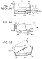
- Fig. 1A is a recording head of the type integrated with an ink tank, having a connecting terminal 101a having a plurality of electrical pads 111 and a discharge port surface of the ink recording head element 101c provided at the bottom.
- the carriage 102 is provided with a connecting terminal 102a for transmitting recording signals to the recording head.
- 102a is constituted of a plurality of electrical pads 112.
- 104 is a guide shaft for guiding movement of the carriage 102.
- unused recording head may sometimes take a constitution in which a very thin insulating protective film 121 is provided for protection of connecting terminals. Then, in the case of such mounting method, there is no action of ensuring connection by scraping off the protective film. Therefore, this example could never be said as the optimum example as the connecting method of signal terminals. Also, in commencing use by mounting unused recording head, it is necessary to form immediately the state where ink can be well discharge by means of a discharge restoration means, etc.
- the present inventors have thought of attaching and detaching the recording head at the home position which becomes the waiting position of the recording head, and protecting the discharged port preferably on completion of mounting of the recording head.
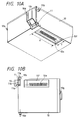
- Fig. 2A mounts a recording head from behind the carriage.
- 101 is the recording head and 102 is the carriage.
- 103 is a discharge restoration device equipped with a cap for protecting the discharge port of the recording head and preventing ink fixing.
- the constitution is such that, by performing mounting of the recording head by inserting the recording head 101 from behind the carriage 102 in the direction of the arrowhead, the recording head 101 is capped at the fixed position, and the connecting terminals 101a and 102a are correctly connected.
- the connecting terminals will be respectively rubbed during mounting successively.
- the electrode pad 101 of the connecting terminal of the recording head located on the discharging port side will be rubbed with all the electrode pads of the carriage 102. Therefore, a part of all of the terminals will be considerably damaged, whereby it has been found that electrical signals cannot be transmitted to cause defective discharging.
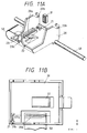
- the present inventors have further thought of a method of mounting by rotation of the recording head 101 as shown in Fig. 2B, but with such constitution, mounting must be done with the discharge port surface 101b which becomes the front surface of the recording head 101, particularly the upper part of 101b being forwarded greatly before the constant position after mounting. Then, a great space is required in front of the carriage.
- the interval between the recording head and the recording paper is designed to be 3.0 mm or less, and therefore it has been found to be difficult to take such constitution. Also, even if mounting may be effected at the home position, because great mutual interference with the cap cannot be avoided, such inconvenience as deformation of cap, etc. has been found to occur.
- an ink jet recording apparatus comprising:
- the present invention also provides an ink cartridge for mounting on a carriage of an ink jet recording apparatus, said cartridge comprising:
- the present invention also provides a method of mounting to a carriage of an ink jet recording apparatus having a first electrical contact portion an ink jet cartridge comprising a recording head having a discharge port for discharging ink and having a second electrical contact portion, comprising:
- An embodiment of the present invention provides an ink jet recording apparatus comprising a recording head capable of effecting electrical connection in connecting the connecting terminals without damaging terminals and which can also scrape off the protective film provided on the terminal surface by mutual rubbing of the terminals with each other, and capable of positioning surely the recording head simultaneously with mounting completion of the recording head and a member for mounting of recording head and a recording head mounting method and an ink jet recording device.
- An embodiment of the present invention provides an ink jet recording apparatus comprising a tank integrated type recording head which can be accurately positioned as the ink jet recording head onto a carriage of the ink jet recording apparatus, which carriage can more surely hold said recording head and wherein the recording head can be accurately held under the desired state relative to within the main body of the apparatus and the carriage.
- An ink jet recording apparatus embodying the present invention can elongate the life of the positioning portion of said head itself which is detachable and of the cap within the main body.
- An ink jet recording apparatus embodying the present invention can perform positioning of the recording head and the carriage with good precision, and with such constitution, accurate positioning of the ink discharge port, and accurate positioning capable of joining pads as unit elements of electrical connecting terminals while rubbing with each other at one to one can be done.
- This embodiment is an ink jet recording head having a discharge port for discharging ink and an energy generation means for generating energy for discharging ink, which is detachable relative to the mounting means for mounting the recording head onto the recording head of ink jet recording means, characterized in that the recording head has a surface having the discharge port provided thereon, an electrical connecting terminal provided on a surface forming a specific angle with respect to the surface and a rotation center portion in attachment and detachment relative to the mounting means of the recording head, the center axis of the rotation center portion is substantially parallel to the surface where the discharge port is provided and the surface where the connecting terminal is provided, with its position being made on the side opposed to the connecting terminal with respect to the surface where the discharge port is provided and outside the range where the discharge port is provided, and on the discharge port side relative to the connecting terminal near the surface side where the discharge port is provided.
- this embodiment provides an ink jet recording device, comprising an ink jet recording head having a discharge port for discharging ink and energy generation means for generating energy for discharging ink, wherein the recording head has a surface having the discharge port provided thereon, an electrical connecting terminal provided on a surface forming a specific angle with respect to the surface and a rotation center portion in attachment and detachment relative to the mounting means of the recording head, the center axis of the rotation center portion is substantially parallel to the surface where the discharge port is provided and the surface where the connecting terminal is provided, with its position being made on the side opposed to the connecting terminal with respect to the surface where the discharge port is provided and outside the range where the discharge port is provided, and on the discharge port side relative to the connecting terminal near the surface side where the discharge port is provided and a mounting means having a site to be engaged to the rotation center for mounting the recording head.
- this embodiment is a method for mounting a recording head having a discharge port for discharging ink, an energy generation means for generating the energy for discharge of the ink through the discharge port and an electrical connecting terminal provided on a surface forming a specific angle with respect to the surface where the discharge port is provided, wherein the recording head is mounted by engaging the rotation center portion having a center axis in parallel to both the surface where the discharge port is provided and the surface where the connecting terminal is provided and located on the side opposed to the connecting terminal with respect to the surface where the discharge port is provided, outside of the range where the discharge port is provided and on the discharge port side relative to the connecting terminal near the surface side where the discharge port is provided, to the site corresponding to the mounting means with the rotation center portion as the center.
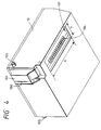
- Fig. 3 is a schematic perspective view of appearance showing the principal part of the recording device.
- Fig. 4 is a schematic perspective view of the recording head according to the embodiment of the present invention as viewed from the bottom side, and
- Fig. 5A is a schematic perspective view according to this embodiment, and
- Fig. 5B is a schematic plan view of the carriage of this embodiment as viewed from above.
- the carriage 20 as the mounting means having the recording head 10 mounted thereon moves along the paper delivery roller 60 as guided by the guide shaft 40.
- the constitution is made such that the recording head 10 discharges ink toward the surface of the recording paper P as the recording medium, and forms an image with the attached ink droplets, thereby performing recording.
- 30 is the discharge restoration means located at the home position of the carriage 20.
- the discharge restoration means is constituted of a cap 31 comprising an elastic material such as rubber, etc. provided for protecting the discharge port by covering over the discharge port and also preventing fixing of ink by prevention of drying of the discharge port vicinity including the discharge port, and a suction pump 33 communicated to the cap 31 through an elastic tube 32.
- the carriage 20 is located at the home position as the non-recording position except when the recording head 10 performs recording, so that the discharge port may be protected there with the cap 31. And, the constitution is made so that attachment and detachment of the recording head 10 may be performed necessarily at the home position.
- the recording head 10 of the ink tank integration type is equipped with a recording head element 10C provided with an electrothermal transducer not shown as the energy generation means for generating thermal energy as the energy to be utilized for discharging of ink.
- a piezoelectric element, etc. can be also employed as the energy generation means.
- the constitution by use of the electrothermal transducer as mentioned above having the advantages of simple constitution, lowered production cost and possibility of high densification may be preferably utilized.
- the recording head element 10c is provided with a plurality of ink discharge ports 10d on the front surface.
- Behind the recording head is provided a fixing hook 10g (see Fig. 6A) for fixing the recording head through engagement with the nail portion of the carriage 20.
- 20a is the connecting terminal bonded to the connecting terminal 10a of the recording head 10, 20b the fitting portion fitted (engaged) to the guide pin 10b of the recording head 10, 20c the elastic member for giving an adequate pressure contact force (20 to 50 g per one terminal) during bonding of the connecting terminals 10a and 20a, for which chloroprene rubber, urethane rubber, moltprene rubber, etc. may be used as preferable material for having optimum modulus of elasticity.
- 22 is a plate spring provided to taking balance with the pressure forces of connecting terminals 10a and 20a, and has the hop-up function during dismantling of the head as described below.
- a projection 23 is engaged with the fixing hook 10g of the recording head 10 to fix and hold the recording head 10.
- 50 is a flexible cable for transmitting electrical signals from the recording control section not shown to the connecting terminal 20a of the carriage.
- Fig. 6A shows the state of mounting initiation state
- Fig. 6B the first state in the course of mounting
- Fig. 6C the second state in the course of mounting
- the Fig. 6D the state on completion of mounting.
- the guide pin 10b namely the rotation center of the recording head 10 is provided within the range AR upwardly of the position corresponding to the cap and in front of the connecting terminal, the front surface (namely discharge port) and the cap 31 of the recording head element 10c, and the connecting terminals 10a and 20a are adequately contacted or connected with each other without interference with other portions.
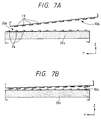
- FIG. 7A to 7E show the manner in which the connecting terminals are bonded to each other.
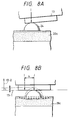
- FIGs. 8A and 8B are schematic illustrations partially enlarged of one of a plurality of electrode pads of connecting terminal, showing the states at the beginning of contact and on completion of connection.
- the plural number of electrode pads 13 of the connecting terminal 10a of the recording head 10 of this embodiment are made of lead frame of metal, etc., with the contact points being made flat.
- the plural number of electrode pads 24 of the connecting terminal 20a of the carriage 20 are worked into semispherical projected shapes by application of plating to the terminal on the flexible cable 50.
- the electrode pads from the discharge port side will contact from the state in Fig. 7A as shown in Fig. 7B, and successively as shown in Fig. 7C. In transferring from Figs. 7B to 7E, the pads are rubbed mutually one to one to maintain good electrical contact.
- the pressure contact force at the contact point of the pad is controlled through deformation of the elastic member 20c, whereby superfluous contact force can be absorbed to give adequate pressure contact force.
- the position of the connecting terminal 20a of the carriage is positioned lower than the position in Fig. 5A, whereby the pressure contact force is applied upwardly with the elastic member 20c.
- Such pressure contact force is balanced with the forces of the projection 23 and the fitting portion 20b of the carriage.
- connection of the terminal is described in detail by referring to Figs. 8A and 8B.
- I shows the contact position of the electrode pad 12 at the beginning of contact
- J the contact position of the electrode pads 13, 24 under the final state.
- the constitution is required to be made such that the rotation center as the standard for rotation should be positioned with a predetermined distance in the direction of the normal line 13-2 of the contact portion of the electrode pad 13 of the recording head from the tangential line 13-1 of the contact portion, and also the electrical pad 24 of the carriage 20 should be dislocated (m > 0) when the head 10 is mounted.
- the ink discharge port 10d, the electrical connecting terminal 10f are all provided on substantially one straight line in the recording head element 10c so as to hold readily the positional relationships of the respective elements with high precision.
- further the above elements are provided on one end side where the recording head is located, and further the cap is located on the above straight line in the home position.
- the positioning member for carriage and electrical connecting terminals can be arranged on one side of the recording head and the carriage, whereby an extremely advantageous constitution in aspect of practical armoring such as withdrawing of flexible cable, etc. is given, and also unsure capping due to positional slippage can be prevented to make the probability of breaking of the recording head and the cap accompanied with mounting actuation of the recording head very lower.
- the mounting method of the first embodiment of the present invention there is no breaking by way of rubbing of connecting terminals than is necessary and the recording head will receive no bad influence from outside, and also, even if foreign matters may be attached on the terminal surface of the recording head, they can be removed to effect mounting of the recording head onto the correct position of the carriage with a force enough to obtain electrical connection.
- attachment and detachment of the recording can be surely done while performing positioning with high precision.
- this embodiment is an ink jet recording head having a discharge port for discharging ink and an energy generation means for generating energy for discharging ink, which is detachable relative to the mounting means for mounting the recording head onto the recording head of an ink jet recording means, characterized in that the recording head has a surface having the discharge port provided thereon, an electrical connecting terminal provided on a surface forming a specific angle with respect to the surface and a rotation center portion in attachment and detachment relative to the mounting means of the recording head, the center axis of the rotation center portion is substantially parallel to the surface where the discharge port is provided and the surface where the connecting terminal is provided, with its position being made on the side opposed to the connecting terminal with respect to the surface where the discharge port is provided and outside the range where the discharge port is provided, and on the discharge port side relative to the connecting terminal near the surface side where the discharge port is provided, and further has a positioning member provided between the discharge port and the connecting terminal.
- an ink jet recording device comprising an ink jet recording head having a discharge port for discharging ink and an energy generation means for generating energy for discharging ink
- the recording head has a surface having the discharge port provided thereon, an electrical connecting terminal provided on a surface forming a specific angle with respect to the surface and a rotation center portion in attachment and detachment relative to the mounting means of the recording head, the center axis of the rotation center portion is substantially parallel to the surface where the discharge port is provided and the surface where the connecting terminal is provided, with its position being made on the side opposed to the connecting terminal with respect to the surface where the discharge port is provided and outside the range where the discharge port is provided, and on the discharge port side relative to the connecting terminal near the surface side where the discharge port is provided, further having a positioning means provided between the discharge port and the connecting terminal, and a mounting means having a member engaged with the positioning member for mounting the recording head.
- Fig. 9 is a schematic perspective view of appearance showing the principal part of the recording device.
- Fig. 10A is a schematic perspective view of the recording to the embodiment of the present invention as viewed from the bottom side
- Fig. 10B is a schematic plan view of the recording head according to this embodiment
- Fig. 11A is a schematic perspective view of the carriage according to this embodiment
- Fig. 11B is a schematic plan view of this embodiments as viewed from above.
- the carriage 20 as the mounting means having the recording head 10 mounted thereon moves along the paper delivery roller 60 as guided by the guide shaft 40.
- Recording head 10 discharges ink toward the surface of the recording paper P as the recording medium, thereby forming an image with the attached ink droplets to effect recording.
- 30 is the discharge restoration means located at the home position of the carriage 20.
- the discharge restoration means is constituted of a cap 31 comprising an elastic material such as rubber, etc. provided for protecting the discharge port by covering over the discharge port and also preventing ink from depositing by prevention of drying of the discharge port vicinity including the discharge port, and a suction pump 33 communicated to the cap 31 through an elastic tube 32.
- the carriage 20 is located at the home position as the non-recording position except when the recording head 10 performs recording, so that the discharge port may be protected there with the cap 31. And, the constitution is made so taht attachment and detachment of the recording head 10 may be performed necessarily at the home position.
- the above-mentioned constitution is the same as in the first embodiment.
- the recording head 10 of the ink tank integration type is equipped with a recording head element 10c provided with an electrothermal transducer not shown as the energy generation means for generating thermal energy as the energy to be utilized for discharging of ink.
- an electrothermal transducer not shown as the energy generation means for generating thermal energy as the energy to be utilized for discharging of ink.
- the energy generation means to be employed for such recording head element otherwise a piezoelectric element, etc. can be also employed.
- the constitution by use of the electrothermal transducer as mentioned above having the advantages of simple constitution, lowered production cost and possibility of high densification may be preferably utilized.
- the recording head element 10c is provided with a plurality of ink discharge ports 10d on the front surface.
- Behind the recording head is provided a fixing hook 10g (see Fig.
- a rib 11 as the positioning member is provided on substantially the straight line connecting the ink discharge port 10d and the connecting terminal 10b. The rib 11 performs positioning through engagement of the positioning member of the carriage 20 as described later.
- 20a is the connecting terminal bonded to the connecting terminal 10a on the carriage side of the recording head 10, 20b the fitting portion fitted to the guide pin 10b of the recording head 10, 20c the connecting terminal 10a, 20a the elastic member for giving an adequate pressure contact force (20 to 50 g per one terminal) during bonding of the 20a, for which chloroprene rubber, urethane rubber, moltprene rubber, etc. may be used as preferable material for having optimum modulus of elasticity.
- 21 is a positioning member formed at the concavity for effecting positioning through engagement with the positioning rib 11 of the recording head 10.
- the positioning member on the inserted side is tapered as shown in Fig. 11B, 22 is a plate spring provided to take balance with the pressure forces of connecting terminals 10a, 20a, and has the hop-up function during dismantling of the head as described below.
- 23 is engaged with the fixing hook 10g of the recording head 10 to fix and hold the recording head 10.
- 50 is a flexible cable for transmitting electrical signals from the recording control section not shown to the connecting terminal 20a of the carriage.
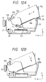
- Fig. 12A shows the state of mounting initiation state
- Fig. 12B the first state in the course of mounting
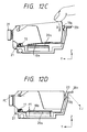
- Fig. 12C the second state in the course of mounting
- the Fig. 12D the state on completion of mounting.
- Fig. 12A when the recording head 10 is placed on the carriage 20, the guide pin 10b of the recording head and the carriage 10 at the bottom of the recording head are guided by the guide surface 20h and the tip end 20t of the lock lever 20i, and moves readily in the direction A in the Figure by the weight of the recording head 1.
- Fig. 12B when the guide pin 10b is fitted into the fitting portion 20b, the rear end portion of the recording head 10 comes off from the lock lever 20i, to rotate the guide pin 10b in the direction C with the guide pin 10b as the center, whereby the fixing hook 10g comes against the lock lever as shown in Fig. 12C.
- the side face 11a of the rib 11 begins to be fitted into the inside face 21a (Fig. 11B) of the positioning member 21 of the carriage 20 to effect positioning in the direction x in Fig. 11B.
- the guide pin 10b namely the rotation center of the recording head 10 is provided within the range PC in Fig. 12D upwardly of the position corresponding to the cap and in front of the position PT of the connecting terminal, the front surface (namely discharge port) and the cap 31 of the recording head element 10c, and the connecting terminals 10a and 20a are adequately contacted or connected with each other without interference with other portions.
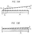
- FIG. 13A through 13E show the manner in which the connecting terminals are bonded to each other.
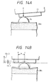
- Figs. 14A and 14B are schematic illustrations partially enlarged of one of a plurality of electrode pads as unit elements of connecting terminal, showing the states at the beginning of contact and on completion of connection.
- the plural number of electrode pads 13 of the connecting terminal 10a of the recording head 10 of this embodiment are made of lead frame of metal, etc., with the contact points being made flat.
- the plural number of electrode pads 24 of the connecting terminal 20a of the carriage 20 are worked into semispherical projected shapes by application of plating to the terminal on the flexible cable 50.
- the electrode pads from the discharge port side will contact from the state in Fig. 13A as shown in Fig. 13B, and successively as shown in Fig. 13C.
- the pads are rubbed mutually one to one to maintain good electrical contact.
- the pressure contact force at the contact point of the pad is controlled through deformation of the elastic member 20c, whereby superfluous contact force can be absorbed to give adequate pressure contact force.
- the position of the connecting terminal 20a of the carriage is positioned lower than the position in Fig. 13A, whereby the pressure contact force is applied upwardly with the elastic member 20c.
- Such pressure contact force is balanced with the forces of the nail 23 and the fitting portion 20b of the carriage.
- connection of the terminal is described in detail by referring to referring to Figs. 14A and 14B.
- I shows the contact position of the electrode pad 12 at the beginning of contact
- J the contact position of the electrode pads 13, 24 under the final state.
- the constitution is required to be made such that the rotation center as the standard for rotation should be positioned with a predetermined distance in the direction of the normal line 13-2 of the contact portion of the electrode pad 13 of the recording head from the tangential line 13-1 of the contact portion, and also the electrical pad 24 of the carriage 20 should be dislocated (m > 0) when the head 10 is mounted.
- the ink discharge port 10d, the positioning rib 11, the electrical connecting terminal 10f are all provided so as to be overlapped at least a part of the respective elements on substantially one straight line in the recording head element 10c, the positional relationships of the three elements can be held with high precision.
- further the above three elements are provided on one end side where the recording head is located, and further the cap is located on the above straight line in the home position.
- the positioning member for carriage and electrical connecting terminals can be arranged on one side of the recording head and the carriage, whereby an extremely advantageous constitution in aspect of practical armoring such as withdrawing of flexible cable, etc. is given, and also unsure capping due to positional slippage can be prevented to make the probability of breaking of the recording head and the cap accompanied with mounting actuation of the recording head very lower.
- the ink discharge port of the head, the positioning member and the electrical connecting member can be arranged in this order on substantially straight line, whereby attachment and detachment of the recording head can be done simply and surely, while positioning the position of the ink discharge port and the position of the electrical connecting terminal relative to the carriage with high precision.
- the cap, the positioning rib and the connecting terminal are on substantially straight line. That is, they are not completely coincident on one straight line, but a part of the respective elements are deviated from the straight line, but of course they can be made coincident with each other.
Landscapes
- Ink Jet (AREA)
Claims (17)
- Tintenstrahlaufzeichnungsgerät, miteinem Wagen (20) zum Einbau einer Titenstrahlkartusche (10), wobei der Wagen einen ersten elektrischen Kontaktabschnitt (20A) hat; und einer Tintenstrahlkartusche zum Einbau in den Wagen (20), wobei die Kartusche, miteinem Aufzeichnungskopf (10c), der mit einer Ausstoßöffnung (10D) zum Ausstoßen von Tinte, einem zweiten elektrischen Kontaktabschnitt (10A) und einem Drehzentrum (10B) vorgesehen ist, um dem Aufzeichnungskopf ein Drehen in seine Einbaustellung im Wagen zu ermöglichen, dadurch gekennzeichnet, daß das Drehzentrum an einer Stelle vorgesehen ist, die näher an der Tintenausstoßöffnung (10D), als an dem zweiten elektrischen Kontaktabschnitt (10A) ist, und daß die Tintenstrahlkartusche (10) durch Drehen um das Drehzentrum (10B) in den Wagen (20) einbaubar ist, wodurch ein Aneinanderreiben des ersten und des zweiten Kontaktabschnittes durch eine im wesentlichen, seitliche Relativbewegung, und eine elektrische Verbindung, die zwischen dem ersten und dem zweiten elektrischen Kontaktabschnitt (10A, 20A) hergestellt werden soll, erzielt wird.
- Tintenstrahlaufzeichnungsgerät nach Anspruch 1, wobei der zweite elektrische Kontaktabschnitt (10A) und die Tintenausstoßöffnung (10D) auf verschiedenen Flächen der Tintenstrahlkartusche (10) vorgesehen sind.
- Tintenstrahlaufzeichnungsgerät nach Anspruch 2, wobei die Tintenausstoßöffnung (10D) auf der Fläche der Vorderseite der Tintenstrahlkartusche (10) angeordnet ist und der zweite elektrische Kontaktabschnitt (10A) auf der Fläche der Unterseite der Tintenstrahlkartusche (10) angeordnet ist.
- Tintenstrahlaufzeichnungsgerät nach Anspruch 2, wobei der Aufzeichnungskopf (10C) eine Ausstoßöffnung (10D) an einer vor einer ersten Oberfläche geschützten Position hat, und wobei der zweite elektrische Kontaktabschnitt (10A) in einer Konkavität in einer Oberfläche senkrecht zur ersten Oberfläche vorgesehen ist.
- Tintenstrahlaufzeichnungsgerät nach einer der vorgehenden Ansprüche, wobei der Aufzeichnungskopf (10C) eingerichtet ist, um durch Ausstoß von Tinte unter Anwendung von Wärmeenergie aufzuzeichnen.
- Tintenstrahlaufzeichnungsgerät nach einer der vorgehenden Ansprüche, wobei die Tintenstrahlkartusche (10) ferner einen Tintenbehälter zur Aufnahme von zum Aufzeichnungskopf (10C) zuzuführender Tinte hat.
- Tintenstrahlaufzeichnungsgerät nach einer der vorgehenden Ansprüche, wobei die Tintenstrahlkartusche (10) eine Führung (10B) zum Führen der Tintenstrahlkartusche (10) während des Einbaus der Tintenstrahlkartusche (10) in den Wagen (20) hat.
- Tintenstrahlaufzeichnungsgerät nach Anspruch 7, wobei die Führung (10B) Führungszapfen hat, die am Drehzentrum vorgesehen sind und wobei der Wagen (20) ferner ein Paßteil (20B) zur Annahme der Führungszapfen hat.
- Tintenstrahlaufzeichnungsgerät nach einer der vorgehenden Ansprüche, wobei die Tintenstrahlkartusche (10) ferner eine Positionierrippe (11) hat und wobei der Wagen (20) ein Positionierelement (21) zur Annahme der Positionierrippe (11) hat.
- Tintenstrahlaufzeichnungsgerät nach einer der vorgehenden Ansprüche, wobei die Tintenstrahlkartusche (10) einen Vorsprung zur Positionierhilfe hat, um die Vorspannkraft zum Befestigen der Tintenstrahlkartusche (10) auf dem Wagen (20) aufzunehmen.
- Tintenstrahlaufzeichnungsgerät nach einer der vorgehenden Ansprüche, wobei der Wagen ferner Ansätze (23) zum Festlegen der Tintenstrahlkartusche (10) in einer Einbaustellung hat, wenn die Tintenstrahlkartusche (10) in dem Wagen (20) eingebaut ist.
- Tintenstrahlaufzeichnungsgerät nach einer der vorgehenden Ansprüche, wobei der erste elektrische Kontaktabschnitt (20A) durch ein elastisches Element (20C) elastisch gehalten ist, das verformbar ist, wenn die Tintenstrahlkartusche (10) in den Wagen (20) eingebaut und um das Drehzentrum (10B) gedreht wird, um den ersten und den zweiten elektrischen Kontaktabschnitt (10A, 20A) durch eine im wesentlichen, seitliche Relativbewegung aneinanderzureiben.
- Tintenstrahlaufzeichnungsgerät nach einer der vorgehenden Ansprüche, wobei der Wagen (20) ferner eine Federplatte (22) hat, die angepaßt ist, den Anpressdruck zwischen den Anschlußklemmen des ersten und zweiten elektrischen Kontaktabschnittes (20A, 10A) auszugleichen.
- Tintenstrahlaufzeichnungsgerät nach einer der vorgehenden Ansprüche, wobei die Anschlußklemmen des ersten elektrischen Kontaktabschnittes (20A) halbkugelförmige Vorsprünge sind und die Anschlußklemmen des zweiten elektrische Kontaktabschnittes (10A) flach sind.
- Tintenkartusche zum Einbau in einen Wagen (20) eines Tintenstrahlaufzeichnungsgerätes, Kartusche, miteinem Aufzeichnungskopf (10C) mit einer Ansstoßöffnung (10D) zum Ausstoß von Tinte, einem elektrischen Kontaktabschnitt (10A), um in Kontakt mit einem elektrischen Kontaktabschnitt (20A) des Wagens zu gelangen, einem Drehzentrum (10B), um den Aufzeichnungskopf in die Einbaustellung im Wagen drehbar zu machen, dadurch gekennzeichnet, daß
das Drehzentrum an einer Stelle vorgesehen ist, die näher an der Ausstoßöffnung (10D) als an dem elektrischen Kontaktabschnitt (10A) des Aufzeichnungskopfes ist, und daß die Tintenstrahlkartusche (10) ausgelegt ist, um in den Wagen (20) durch Drehen um das Drehzentrum (10B) eingebaut zu werden, wodurch der elektrische Kontaktabschnitt des Aufzeichnungskopfes und des Wagens durch eine im wesentlichen, seitliche Relativbewegung aneinanderreiben und eine elektrische Verbindung zwischen den elektrischen Kontaktabschnitten (10A, 10B) des Aufzeichnungskopfes und der Kartusche hergestellt wird. - Verfahren zum Einbau in einen Wagen (20) eines Tintenstrahlaufzeichnungsgerätes mit einem ersten elektrischen Kontaktabschnitt (20a), einer Tintenstrahlkartusche (10), die einen Aufzeichnungskopf (10C) mit einer Ausstoßöffnung (10D) zum Ausstoßen von Tinte und einen zweiten elektrischen Kontaktabschnitt (10A) hat, mit:Einsetzen der Kartusche in den Wagen durch Drehen der Tintenstrahlkartusche (10) um sein Drehzentrum (10B), das näher an der Ausstoßöffnung (10D) als an dem zweiten elektrischen Kontaktabschnitt (10A) angeordnet ist, um den ersten und den zweiten elektrischen Kontaktabschnitt in Kontakt zu bringen und um sie durch eine im wesentlichen, seitliche Relativbewegung aneinanderzureiben, so daß eine elektrische Verbindung zwischen dem ersten und den zweiten elektrischen Kontaktabschnitt hergestellt wird.
- Verfahren nach Anspruch 16, wobei der erste elektrische Kontaktabschnitt elastisch gehalten ist und die im wesentlichen, seitliche Relativbewegung zwischen dem ersten und dem zweiten elektrischen Kontaktabschnitt (10a, 20a) durch eine Verschiebung des elektrisch verbundenen ersten elektrischen Kontaktabschnittes (20a) verursacht wird.
Applications Claiming Priority (7)
| Application Number | Priority Date | Filing Date | Title |
|---|---|---|---|
| JP330996/88 | 1988-12-29 | ||
| JP63330996A JP2763310B2 (ja) | 1988-12-29 | 1988-12-29 | インクジェットカートリッジ |
| JP63330981A JP2728912B2 (ja) | 1988-12-29 | 1988-12-29 | インクジェットカートリッジ及びインクジェット記録装置 |
| JP330981/88 | 1988-12-29 | ||
| JP807689A JP2698638B2 (ja) | 1989-01-17 | 1989-01-17 | インクタンク一体型記録ヘッドカートリッジ、該カートリッジを搭載するキャリッジおよびこれらを用いるインクジェット記録装置 |
| JP8076/89 | 1989-01-17 | ||
| EP89313644A EP0376719B1 (de) | 1988-12-29 | 1989-12-28 | Tintenstrahlaufzeichnungskopf und Tintenstrahlaufzeichnungsgerät |
Related Parent Applications (2)
| Application Number | Title | Priority Date | Filing Date |
|---|---|---|---|
| EP89313644A Division EP0376719B1 (de) | 1988-12-29 | 1989-12-28 | Tintenstrahlaufzeichnungskopf und Tintenstrahlaufzeichnungsgerät |
| EP89313644.0 Division | 1989-12-28 |
Publications (3)
| Publication Number | Publication Date |
|---|---|
| EP0602020A2 EP0602020A2 (de) | 1994-06-15 |
| EP0602020A3 EP0602020A3 (en) | 1994-09-21 |
| EP0602020B1 true EP0602020B1 (de) | 1998-06-10 |
Family
ID=27277864
Family Applications (2)
| Application Number | Title | Priority Date | Filing Date |
|---|---|---|---|
| EP94200470A Expired - Lifetime EP0602020B1 (de) | 1988-12-29 | 1989-12-28 | Tintenstrahlaufzeichnungskopf und Tintenstrahlaufzeichnungsgerät |
| EP89313644A Expired - Lifetime EP0376719B1 (de) | 1988-12-29 | 1989-12-28 | Tintenstrahlaufzeichnungskopf und Tintenstrahlaufzeichnungsgerät |
Family Applications After (1)
| Application Number | Title | Priority Date | Filing Date |
|---|---|---|---|
| EP89313644A Expired - Lifetime EP0376719B1 (de) | 1988-12-29 | 1989-12-28 | Tintenstrahlaufzeichnungskopf und Tintenstrahlaufzeichnungsgerät |
Country Status (5)
| Country | Link |
|---|---|
| US (3) | US5245361A (de) |
| EP (2) | EP0602020B1 (de) |
| KR (1) | KR930011859B1 (de) |
| DE (2) | DE68918074T2 (de) |
| ES (1) | ES2058563T3 (de) |
Families Citing this family (88)
| Publication number | Priority date | Publication date | Assignee | Title |
|---|---|---|---|---|
| JP2622178B2 (ja) * | 1989-01-17 | 1997-06-18 | キヤノン株式会社 | インクジェットカートリッジ及び該カートリッジを用いたインクジェット記録装置 |
| US5187497A (en) * | 1989-09-18 | 1993-02-16 | Canon Kabushiki Kaisha | Ink jet recording apparatus having gap adjustment between the recording head and recording medium |
| US5461405A (en) * | 1989-10-30 | 1995-10-24 | Eastman Kodak Company | Ink jet printer device with exchangeable printheads |
| US5579039A (en) * | 1990-07-31 | 1996-11-26 | Canon Kabushiki Kaisha | Ink jet recording apparatus |
| US5208610A (en) * | 1991-07-31 | 1993-05-04 | Hewlett-Packard Company | Pen carriage for an ink-jet printer |
| DE69229509T2 (de) * | 1991-12-11 | 1999-11-25 | Canon K.K., Tokio/Tokyo | Tintenstrahlkassette und Titenbehälter |
| US6003985A (en) * | 1991-12-11 | 1999-12-21 | Canon Kabushiki Kaisha | Ink jet recording apparatus |
| CA2084708C (en) * | 1991-12-11 | 1997-11-25 | Hiromitsu Hirabayashi | Ink jet recording apparatus and carriage mechanism therefor |
| CA2290698C (en) * | 1992-07-24 | 2003-12-23 | Canon Kabushiki Kaisha | Ink container, ink and ink jet recording apparatus using ink container |
| US6332675B1 (en) | 1992-07-24 | 2001-12-25 | Canon Kabushiki Kaisha | Ink container, ink and ink jet recording apparatus using ink container |
| US5561450A (en) * | 1992-09-30 | 1996-10-01 | Pitney Bowes Inc. | Apparatus for mounting an ink jet cartridge on a support therefor |
| US5988784A (en) * | 1992-11-12 | 1999-11-23 | Canon Kabushiki Kaisha | Method and apparatus for recording information with corrected drive timing |
| JP2839997B2 (ja) * | 1992-12-09 | 1998-12-24 | 株式会社リコー | 記録ヘッドユニット |
| EP0604127B1 (de) * | 1992-12-22 | 1997-07-02 | Hewlett-Packard Company | Tintenstrahlkassette mit Doppelbehälter und optimalem Mundstück |
| TW297332U (en) | 1993-01-19 | 1997-02-01 | Canon Kk | Ink jet cartridge, ink jet apparatus and ink container |
| US5392063A (en) * | 1993-04-30 | 1995-02-21 | Hewlett-Packard Company | Spring cartridge clamp for inkjet printer carriage |
| US5598194A (en) * | 1993-04-30 | 1997-01-28 | Hewlett-Packard Company | Wiping structure for cleaning electrical contacts for a printer and ink cartridge |
| US5461482A (en) * | 1993-04-30 | 1995-10-24 | Hewlett-Packard Company | Electrical interconnect system for a printer |
| JP3188056B2 (ja) * | 1993-07-21 | 2001-07-16 | キヤノン株式会社 | インクジェット記録装置およびインクジェットヘッド |
| JP3217610B2 (ja) * | 1993-09-03 | 2001-10-09 | キヤノン株式会社 | インクジェット記録装置および情報処理システム |
| JP3332590B2 (ja) * | 1993-10-29 | 2002-10-07 | キヤノン株式会社 | 記録装置 |
| US5796417A (en) * | 1993-10-29 | 1998-08-18 | Hewlett-Packard Company | Compliant interconnect assembly for mounting removable print cartridges in a carriage |
| US5619239A (en) * | 1993-11-29 | 1997-04-08 | Canon Kabushiki Kaisha | Replaceable ink tank |
| US5565900A (en) * | 1994-02-04 | 1996-10-15 | Hewlett-Packard Company | Unit print head assembly for ink-jet printing |
| US6305786B1 (en) | 1994-02-23 | 2001-10-23 | Hewlett-Packard Company | Unit print head assembly for an ink-jet printer |
| US5548311A (en) * | 1994-02-28 | 1996-08-20 | Spectra, Inc. | Mount for replaceable ink jet head |
| JP3374608B2 (ja) * | 1994-08-04 | 2003-02-10 | キヤノン株式会社 | 情報処理装置および該情報処理装置に装着可能なヘッド部材 |
| AU741502B2 (en) * | 1994-08-24 | 2001-11-29 | Canon Kabushiki Kaisha | Ink container for ink jet printer, holder for the container carriage for the holder and ink jet printer |
| JP2801149B2 (ja) * | 1994-08-24 | 1998-09-21 | キヤノン株式会社 | インクタンクおよびインクタンクホルダ |
| AU773523B2 (en) * | 1994-08-24 | 2004-05-27 | Canon Kabushiki Kaisha | Ink container for ink jet printer, holder for the container carriage for the holder and ink jet printer |
| CA2402558C (en) * | 1994-08-24 | 2004-06-08 | Canon Kabushiki Kaisha | Ink container for ink jet printer, holder for the container carriage for the holder and ink jet printer |
| AU724462B2 (en) * | 1994-08-24 | 2000-09-21 | Canon Kabushiki Kaisha | Ink container for ink jet printer, holder for the container carriage for the holder and ink jet printer |
| US6142617A (en) * | 1995-04-27 | 2000-11-07 | Hewlett-Packard Company | Ink container configured for use with compact supply station |
| KR0126866Y1 (ko) * | 1995-06-01 | 1998-12-01 | 김광호 | 잉크제트 프린터의 헤드보관용기 |
| US6027208A (en) * | 1995-09-29 | 2000-02-22 | Rohm Co. Ltd. | Ink jet printhead with passage forming panel and vibration plate |
| US6074042A (en) * | 1997-06-04 | 2000-06-13 | Hewlett-Packard Company | Ink container having a guide feature for insuring reliable fluid, air and electrical connections to a printing system |
| JP3295339B2 (ja) * | 1996-08-30 | 2002-06-24 | キヤノン株式会社 | インクタンク、ホルダー、インクジェットカートリッジおよびキャップ |
| US5992986A (en) * | 1997-03-12 | 1999-11-30 | Raster Graphics, Inc. | Ink supply apparatus |
| JP3912568B2 (ja) * | 1997-11-07 | 2007-05-09 | ブラザー工業株式会社 | 印字装置 |
| JP3535713B2 (ja) | 1997-11-14 | 2004-06-07 | キヤノン株式会社 | インクジェット記録装置 |
| CN1880085B (zh) * | 1998-05-18 | 2011-06-15 | 精工爱普生株式会社 | 墨盒 |
| JP2000263813A (ja) * | 1999-03-19 | 2000-09-26 | Canon Inc | インクタンク |
| JP2001010078A (ja) * | 1999-04-27 | 2001-01-16 | Canon Inc | インクタンク、該インクタンクが取り付けられるホルダー、該ホルダーを備えたインクジェット記録装置、インクタンクのホルダーへの装着方法 |
| DE60031213T2 (de) * | 1999-09-03 | 2007-08-23 | Canon K.K. | Flüssigkeitsdruckkopf, Drucker, und Verfahren zum positionieren des Flüssigkeitsdruckkopfs im Drucker |
| US6155678A (en) * | 1999-10-06 | 2000-12-05 | Lexmark International, Inc. | Replaceable ink cartridge for ink jet pen |
| US6196665B1 (en) * | 1999-12-03 | 2001-03-06 | Transact Technologies, Inc. | Latch for an ink cartridge |
| US6499826B1 (en) * | 2000-01-05 | 2002-12-31 | Hewlett-Packard Company | Horizontally loadable carriage for an ink-jet printer |
| US6296345B1 (en) * | 2000-01-05 | 2001-10-02 | Hewlett-Packard Company | Method and apparatus for horizontally loading and unloading an ink-jet print cartridge from a carriage |
| US6827432B2 (en) * | 2000-01-31 | 2004-12-07 | Hewlett-Packard Development Company, L.P. | Replaceable ink container for an inkjet printing system |
| US6431697B1 (en) * | 2000-01-31 | 2002-08-13 | Hewlett-Packard Company | Replaceable ink container having a separately attachable latch and method for assembling the container |
| EP1145860A1 (de) * | 2000-04-13 | 2001-10-17 | Eastman Kodak Company | Von einem Tintenstrahldruckkopf abnehmbare Kartusche |
| US6824247B2 (en) * | 2000-07-19 | 2004-11-30 | Legacy Manufacturing, Llc | Printer cartridge compatible with printhead |
| AU2004203198B2 (en) * | 2000-10-20 | 2005-07-21 | Memjet Technology Limited | Modular pagewidth printhead having replaceable printhead modules |
| US6655786B1 (en) | 2000-10-20 | 2003-12-02 | Silverbrook Research Pty Ltd | Mounting of printhead in support member of six color inkjet modular printhead |
| DE60144193D1 (de) * | 2000-10-23 | 2011-04-21 | Hewlett Packard Ind Printing | Vorrichtung und verfahren zum schutz von druckköpfen |
| JP2002254673A (ja) * | 2000-12-25 | 2002-09-11 | Seiko Epson Corp | インクジェット記録装置用インクカートリッジ |
| US6969148B2 (en) | 2001-07-31 | 2005-11-29 | Hewlett-Packard Development Company, L.P. | Pivoting on-axis ink reservoir for inkjet printer |
| US6623105B1 (en) * | 2001-08-15 | 2003-09-23 | Addmaster Corporation | Printhead cartridge latching assembly |
| US6481829B1 (en) | 2001-09-18 | 2002-11-19 | Lexmark International, Inc. | Manually actuated carrier latch mechanism |
| US6749292B2 (en) | 2001-10-18 | 2004-06-15 | Hewlett-Packard Development Company, L.P. | Replaceable ink container for an inkjet printing system |
| US6464339B1 (en) * | 2001-10-25 | 2002-10-15 | Hewlett-Packard Company | Fluid interconnect port seal with lock-out tab |
| DE10346139A1 (de) * | 2003-10-01 | 2005-04-21 | Artech Gmbh Design & Prod | Tintenkartusche für einen Tintenstrahldurcker |
| US20050078997A1 (en) * | 2003-10-09 | 2005-04-14 | Hewlett-Packard Development Company, L.P. | Print cartridge support system |
| US7025440B2 (en) * | 2003-10-15 | 2006-04-11 | Lexmark International, Inc. | Low profile ink jet cartridge assembly |
| JP4058434B2 (ja) | 2003-12-26 | 2008-03-12 | キヤノン株式会社 | インク収納容器、該容器の製造方法およびプリンタシステム |
| JP4058436B2 (ja) * | 2003-12-26 | 2008-03-12 | キヤノン株式会社 | インク収納容器 |
| US7904728B2 (en) * | 2004-04-22 | 2011-03-08 | Hewlett-Packard Development Company, L.P. | Consumable resource access control |
| US20050249519A1 (en) * | 2004-05-06 | 2005-11-10 | Rec & Assign | Cartridge for toner having removable seal |
| US7755782B2 (en) * | 2004-06-25 | 2010-07-13 | Hewlett-Packard Development Company, L.P. | Consumable resource option control |
| US7706019B2 (en) * | 2004-06-25 | 2010-04-27 | Hewlett-Packard Development Company, L.P. | Consumable resource option control |
| JP4632433B2 (ja) | 2005-04-27 | 2011-02-16 | キヤノン株式会社 | 記録装置 |
| JP4689347B2 (ja) * | 2005-05-19 | 2011-05-25 | キヤノン株式会社 | 記録装置 |
| CN2832527Y (zh) * | 2005-08-30 | 2006-11-01 | 珠海纳思达电子科技有限公司 | 一种分体式发光墨盒 |
| US7658463B2 (en) * | 2005-10-11 | 2010-02-09 | Silverbrook Research Pty Ltd | Printhead maintenance assembly comprising first and second rollers |
| US7669958B2 (en) * | 2005-10-11 | 2010-03-02 | Silverbrook Research Pty Ltd | Printhead cartridge comprising integral printhead maintenance station with maintenance roller |
| DE102006017045A1 (de) * | 2006-04-11 | 2007-04-19 | 3T Supplies Ag | Tintenkassette |
| US20080122904A1 (en) * | 2006-11-28 | 2008-05-29 | Benq Corporation | Printing apparatus having inkjet cartridge |
| US7766568B2 (en) * | 2007-10-15 | 2010-08-03 | Lexmark International, Inc. | Printhead carrier having zero clearance bearing arrangement |
| US8220903B2 (en) * | 2009-11-18 | 2012-07-17 | Eastman Kodak Company | Ink tank feature for improved mounting reliability |
| US8313180B2 (en) * | 2010-03-31 | 2012-11-20 | Eastman Kodak Company | Inkjet ink tank |
| US8317300B2 (en) * | 2010-03-31 | 2012-11-27 | Eastman Kodak Company | Inkjet printer |
| US8857956B2 (en) | 2011-12-06 | 2014-10-14 | Brother Kogyo Kabushiki Kaisha | Cartridges and recording apparatuses |
| JP6019576B2 (ja) * | 2011-12-13 | 2016-11-02 | 株式会社リコー | 画像形成装置 |
| CA2912560C (en) | 2012-01-13 | 2017-11-21 | Seiko Epson Corporation | Cartridge, printing material supply system, printing apparatus, liquid accommodation container, a printing system, and a terminal connection structure |
| JP6255601B2 (ja) * | 2013-03-27 | 2018-01-10 | セイコーエプソン株式会社 | 画像記録装置 |
| EP3337664B1 (de) * | 2015-12-18 | 2021-01-27 | Hewlett-Packard Development Company, L.P. | Halterungen |
| US9744784B1 (en) * | 2016-02-05 | 2017-08-29 | Zih Corp. | Printhead carriers and adapters |
| KR20180113388A (ko) | 2017-04-06 | 2018-10-16 | 우경제 | 묵 국수 제조방법 및 조성물 |
Family Cites Families (20)
| Publication number | Priority date | Publication date | Assignee | Title |
|---|---|---|---|---|
| JPS52150029A (en) * | 1976-06-07 | 1977-12-13 | Konishiroku Photo Ind Co Ltd | Ink jet recording device |
| JPS54117205A (en) * | 1978-03-03 | 1979-09-12 | Canon Kk | Recording liquid |
| DE3051198C2 (de) * | 1979-10-23 | 1996-11-14 | Canon Kk | Abdeck- und Absaugvorrichtung für Tintenstrahlschreiber |
| JP2610011B2 (ja) * | 1984-03-14 | 1997-05-14 | キヤノン株式会社 | インクジエツト記録装置 |
| US4660056A (en) * | 1984-03-23 | 1987-04-21 | Canon Kabushiki Kaisha | Liquid jet recording head |
| US4633274A (en) * | 1984-03-30 | 1986-12-30 | Canon Kabushiki Kaisha | Liquid ejection recording apparatus |
| US4630078A (en) * | 1984-03-30 | 1986-12-16 | Canon Kabushiki Kaisha | Liquid recording head |
| US4635080A (en) * | 1984-03-30 | 1987-01-06 | Canon Kabushiki Kaisha | Liquid injection recording apparatus |
| US4599625A (en) * | 1984-03-30 | 1986-07-08 | Canon Kabushiki Kaisha | Ink tank frangible lever for pressure co-action with a ink bag |
| JPS60219060A (ja) * | 1984-04-17 | 1985-11-01 | Canon Inc | 液体噴射記録装置 |
| JPS6135955A (ja) * | 1984-07-30 | 1986-02-20 | Canon Inc | 液体噴射記録ヘツド |
| JPS61158465A (ja) * | 1984-12-28 | 1986-07-18 | Canon Inc | インクジエツト記録装置 |
| JPS6255146A (ja) * | 1985-09-04 | 1987-03-10 | Canon Inc | インクジエツト記録装置 |
| US4734717A (en) * | 1986-12-22 | 1988-03-29 | Eastman Kodak Company | Insertable, multi-array print/cartridge |
| US4736213A (en) * | 1986-12-22 | 1988-04-05 | Eastman Kodak Company | Multiple print/cartridge ink jet printer having accurate vertical interpositioning |
| US4872026A (en) * | 1987-03-11 | 1989-10-03 | Hewlett-Packard Company | Ink-jet printer with printhead carriage alignment mechanism |
| US4806106A (en) * | 1987-04-09 | 1989-02-21 | Hewlett-Packard Company | Interconnect lead frame for thermal ink jet printhead and methods of manufacture |
| US4755836A (en) * | 1987-05-05 | 1988-07-05 | Hewlett-Packard Company | Printhead cartridge and carriage assembly |
| US4907018A (en) * | 1988-11-21 | 1990-03-06 | Hewlett-Packard Company | Printhead-carriage alignment and electrical interconnect lock-in mechanism |
| US5182581A (en) * | 1988-07-26 | 1993-01-26 | Canon Kabushiki Kaisha | Ink jet recording unit having an ink tank section containing porous material and a recording head section |
-
1989
- 1989-12-28 EP EP94200470A patent/EP0602020B1/de not_active Expired - Lifetime
- 1989-12-28 DE DE68918074T patent/DE68918074T2/de not_active Expired - Lifetime
- 1989-12-28 US US07/458,539 patent/US5245361A/en not_active Expired - Lifetime
- 1989-12-28 DE DE68928706T patent/DE68928706T2/de not_active Expired - Fee Related
- 1989-12-28 ES ES89313644T patent/ES2058563T3/es not_active Expired - Lifetime
- 1989-12-28 EP EP89313644A patent/EP0376719B1/de not_active Expired - Lifetime
- 1989-12-29 KR KR8920125A patent/KR930011859B1/ko not_active Expired - Lifetime
-
1994
- 1994-06-09 US US08/257,488 patent/US5847731A/en not_active Expired - Lifetime
-
1995
- 1995-02-17 US US08/390,170 patent/US5861901A/en not_active Expired - Lifetime
Also Published As
| Publication number | Publication date |
|---|---|
| EP0376719A3 (de) | 1991-07-24 |
| EP0376719A2 (de) | 1990-07-04 |
| US5847731A (en) | 1998-12-08 |
| EP0602020A3 (en) | 1994-09-21 |
| DE68928706D1 (de) | 1998-07-16 |
| US5861901A (en) | 1999-01-19 |
| DE68918074D1 (de) | 1994-10-13 |
| EP0376719B1 (de) | 1994-09-07 |
| ES2058563T3 (es) | 1994-11-01 |
| US5245361A (en) | 1993-09-14 |
| EP0602020A2 (de) | 1994-06-15 |
| KR930011859B1 (en) | 1993-12-21 |
| DE68918074T2 (de) | 1995-01-26 |
| DE68928706T2 (de) | 1998-12-10 |
Similar Documents
| Publication | Publication Date | Title |
|---|---|---|
| EP0602020B1 (de) | Tintenstrahlaufzeichnungskopf und Tintenstrahlaufzeichnungsgerät | |
| EP0581298B1 (de) | Farbstrahlaufzeichnungskopf, Kassette für einen Tintenstrahlaufzeichnungskopf, Aufzeichnungsgerät damit versehen und Herstellungsverfahren des Kopfes | |
| EP0546544B1 (de) | Tintenstrahlaufzeichnungsgerät | |
| KR100851096B1 (ko) | 액체 용기 | |
| US6464338B1 (en) | Ink jet head with separable tank holding member and recording unit | |
| EP0498117A2 (de) | Tintentbehalter und Herstellungsverfahren | |
| JP4027111B2 (ja) | 液体噴射記録ヘッド | |
| US7618123B2 (en) | Liquid ejection head, recording apparatus having same and manufacturing method therefor | |
| KR970001596B1 (ko) | 잉크제트기록헤드, 잉크제트기록헤드카트리지 및 이를 구비한 잉크제트 기록장치 | |
| JP2698638B2 (ja) | インクタンク一体型記録ヘッドカートリッジ、該カートリッジを搭載するキャリッジおよびこれらを用いるインクジェット記録装置 | |
| JP2728912B2 (ja) | インクジェットカートリッジ及びインクジェット記録装置 | |
| JP2763310B2 (ja) | インクジェットカートリッジ | |
| EP0860280A2 (de) | Verfahren und Gerät für das Verbinden von Leiterplatten, Tintenstrahldruckkopf und Aufzeichnungsgerät | |
| US6113215A (en) | Recording apparatus with an ink tank useful for having said recording apparatus, and an information processing equipment having said recording apparatus | |
| JP2746632B2 (ja) | 液体噴射記録装置 | |
| JP2003237071A (ja) | 液体噴射記録ヘッドおよび記録装置 | |
| JPH05169660A (ja) | インクジェット記録ヘッド及び該ヘッドを具備するインクジェット記録装置 | |
| JPH0615811A (ja) | インクジェット記録ヘッド及びこれを搭載した記録装置 | |
| JPH05169662A (ja) | インクジェット記録ヘッド、インクジェット記録ヘッドカートリッジ及びこれを搭載した記録装置 | |
| HK1148502A (en) | Liquid container |
Legal Events
| Date | Code | Title | Description |
|---|---|---|---|
| PUAI | Public reference made under article 153(3) epc to a published international application that has entered the european phase |
Free format text: ORIGINAL CODE: 0009012 |
|
| AC | Divisional application: reference to earlier application |
Ref document number: 376719 Country of ref document: EP |
|
| AK | Designated contracting states |
Kind code of ref document: A2 Designated state(s): DE ES FR GB IT NL |
|
| PUAL | Search report despatched |
Free format text: ORIGINAL CODE: 0009013 |
|
| AK | Designated contracting states |
Kind code of ref document: A3 Designated state(s): DE ES FR GB IT NL |
|
| 17P | Request for examination filed |
Effective date: 19950207 |
|
| 17Q | First examination report despatched |
Effective date: 19960227 |
|
| GRAG | Despatch of communication of intention to grant |
Free format text: ORIGINAL CODE: EPIDOS AGRA |
|
| GRAG | Despatch of communication of intention to grant |
Free format text: ORIGINAL CODE: EPIDOS AGRA |
|
| GRAH | Despatch of communication of intention to grant a patent |
Free format text: ORIGINAL CODE: EPIDOS IGRA |
|
| GRAH | Despatch of communication of intention to grant a patent |
Free format text: ORIGINAL CODE: EPIDOS IGRA |
|
| GRAA | (expected) grant |
Free format text: ORIGINAL CODE: 0009210 |
|
| AC | Divisional application: reference to earlier application |
Ref document number: 376719 Country of ref document: EP |
|
| AK | Designated contracting states |
Kind code of ref document: B1 Designated state(s): DE ES FR GB IT NL |
|
| PG25 | Lapsed in a contracting state [announced via postgrant information from national office to epo] |
Ref country code: NL Free format text: LAPSE BECAUSE OF FAILURE TO SUBMIT A TRANSLATION OF THE DESCRIPTION OR TO PAY THE FEE WITHIN THE PRESCRIBED TIME-LIMIT Effective date: 19980610 Ref country code: ES Free format text: THE PATENT HAS BEEN ANNULLED BY A DECISION OF A NATIONAL AUTHORITY Effective date: 19980610 |
|
| REF | Corresponds to: |
Ref document number: 68928706 Country of ref document: DE Date of ref document: 19980716 |
|
| ITF | It: translation for a ep patent filed | ||
| ET | Fr: translation filed | ||
| NLV1 | Nl: lapsed or annulled due to failure to fulfill the requirements of art. 29p and 29m of the patents act | ||
| PLBE | No opposition filed within time limit |
Free format text: ORIGINAL CODE: 0009261 |
|
| STAA | Information on the status of an ep patent application or granted ep patent |
Free format text: STATUS: NO OPPOSITION FILED WITHIN TIME LIMIT |
|
| 26N | No opposition filed | ||
| REG | Reference to a national code |
Ref country code: GB Ref legal event code: IF02 |
|
| PGFP | Annual fee paid to national office [announced via postgrant information from national office to epo] |
Ref country code: IT Payment date: 20071218 Year of fee payment: 19 |
|
| PGFP | Annual fee paid to national office [announced via postgrant information from national office to epo] |
Ref country code: GB Payment date: 20071228 Year of fee payment: 19 |
|
| PGFP | Annual fee paid to national office [announced via postgrant information from national office to epo] |
Ref country code: DE Payment date: 20071231 Year of fee payment: 19 |
|
| PGFP | Annual fee paid to national office [announced via postgrant information from national office to epo] |
Ref country code: FR Payment date: 20071220 Year of fee payment: 19 |
|
| GBPC | Gb: european patent ceased through non-payment of renewal fee |
Effective date: 20081228 |
|
| REG | Reference to a national code |
Ref country code: FR Ref legal event code: ST Effective date: 20090831 |
|
| PG25 | Lapsed in a contracting state [announced via postgrant information from national office to epo] |
Ref country code: DE Free format text: LAPSE BECAUSE OF NON-PAYMENT OF DUE FEES Effective date: 20090701 |
|
| PG25 | Lapsed in a contracting state [announced via postgrant information from national office to epo] |
Ref country code: GB Free format text: LAPSE BECAUSE OF NON-PAYMENT OF DUE FEES Effective date: 20081228 |
|
| PG25 | Lapsed in a contracting state [announced via postgrant information from national office to epo] |
Ref country code: FR Free format text: LAPSE BECAUSE OF NON-PAYMENT OF DUE FEES Effective date: 20081231 |
|
| PG25 | Lapsed in a contracting state [announced via postgrant information from national office to epo] |
Ref country code: IT Free format text: LAPSE BECAUSE OF NON-PAYMENT OF DUE FEES Effective date: 20081228 |