EP0601570A1 - Ventiltrieb für Brennkraftmaschine - Google Patents
Ventiltrieb für Brennkraftmaschine Download PDFInfo
- Publication number
- EP0601570A1 EP0601570A1 EP93119812A EP93119812A EP0601570A1 EP 0601570 A1 EP0601570 A1 EP 0601570A1 EP 93119812 A EP93119812 A EP 93119812A EP 93119812 A EP93119812 A EP 93119812A EP 0601570 A1 EP0601570 A1 EP 0601570A1
- Authority
- EP
- European Patent Office
- Prior art keywords
- valve
- intake
- internal combustion
- combustion engine
- rocker arm
- Prior art date
- Legal status (The legal status is an assumption and is not a legal conclusion. Google has not performed a legal analysis and makes no representation as to the accuracy of the status listed.)
- Granted
Links
- 238000002485 combustion reaction Methods 0.000 title claims abstract description 37
- 230000007246 mechanism Effects 0.000 claims abstract description 11
- 238000010276 construction Methods 0.000 description 8
- 230000001133 acceleration Effects 0.000 description 5
- 230000006835 compression Effects 0.000 description 3
- 238000007906 compression Methods 0.000 description 3
- 238000004891 communication Methods 0.000 description 2
- 238000000034 method Methods 0.000 description 2
- 230000029058 respiratory gaseous exchange Effects 0.000 description 2
- 230000000712 assembly Effects 0.000 description 1
- 238000000429 assembly Methods 0.000 description 1
- 230000007547 defect Effects 0.000 description 1
- 230000001419 dependent effect Effects 0.000 description 1
- 230000006698 induction Effects 0.000 description 1
- 238000012986 modification Methods 0.000 description 1
- 230000004048 modification Effects 0.000 description 1
Images


Classifications
-
- F—MECHANICAL ENGINEERING; LIGHTING; HEATING; WEAPONS; BLASTING
- F01—MACHINES OR ENGINES IN GENERAL; ENGINE PLANTS IN GENERAL; STEAM ENGINES
- F01L—CYCLICALLY OPERATING VALVES FOR MACHINES OR ENGINES
- F01L1/00—Valve-gear or valve arrangements, e.g. lift-valve gear
- F01L1/02—Valve drive
- F01L1/04—Valve drive by means of cams, camshafts, cam discs, eccentrics or the like
- F01L1/047—Camshafts
- F01L1/053—Camshafts overhead type
-
- F—MECHANICAL ENGINEERING; LIGHTING; HEATING; WEAPONS; BLASTING
- F01—MACHINES OR ENGINES IN GENERAL; ENGINE PLANTS IN GENERAL; STEAM ENGINES
- F01L—CYCLICALLY OPERATING VALVES FOR MACHINES OR ENGINES
- F01L1/00—Valve-gear or valve arrangements, e.g. lift-valve gear
- F01L1/02—Valve drive
- F01L1/04—Valve drive by means of cams, camshafts, cam discs, eccentrics or the like
- F01L1/08—Shape of cams
-
- F—MECHANICAL ENGINEERING; LIGHTING; HEATING; WEAPONS; BLASTING
- F01—MACHINES OR ENGINES IN GENERAL; ENGINE PLANTS IN GENERAL; STEAM ENGINES
- F01L—CYCLICALLY OPERATING VALVES FOR MACHINES OR ENGINES
- F01L1/00—Valve-gear or valve arrangements, e.g. lift-valve gear
- F01L1/12—Transmitting gear between valve drive and valve
- F01L1/18—Rocking arms or levers
- F01L1/185—Overhead end-pivot rocking arms
-
- F—MECHANICAL ENGINEERING; LIGHTING; HEATING; WEAPONS; BLASTING
- F01—MACHINES OR ENGINES IN GENERAL; ENGINE PLANTS IN GENERAL; STEAM ENGINES
- F01L—CYCLICALLY OPERATING VALVES FOR MACHINES OR ENGINES
- F01L1/00—Valve-gear or valve arrangements, e.g. lift-valve gear
- F01L1/26—Valve-gear or valve arrangements, e.g. lift-valve gear characterised by the provision of two or more valves operated simultaneously by same transmitting-gear; peculiar to machines or engines with more than two lift-valves per cylinder
-
- F—MECHANICAL ENGINEERING; LIGHTING; HEATING; WEAPONS; BLASTING
- F01—MACHINES OR ENGINES IN GENERAL; ENGINE PLANTS IN GENERAL; STEAM ENGINES
- F01L—CYCLICALLY OPERATING VALVES FOR MACHINES OR ENGINES
- F01L1/00—Valve-gear or valve arrangements, e.g. lift-valve gear
- F01L1/02—Valve drive
- F01L1/04—Valve drive by means of cams, camshafts, cam discs, eccentrics or the like
- F01L1/047—Camshafts
- F01L1/053—Camshafts overhead type
- F01L2001/0537—Double overhead camshafts [DOHC]
-
- F—MECHANICAL ENGINEERING; LIGHTING; HEATING; WEAPONS; BLASTING
- F02—COMBUSTION ENGINES; HOT-GAS OR COMBUSTION-PRODUCT ENGINE PLANTS
- F02B—INTERNAL-COMBUSTION PISTON ENGINES; COMBUSTION ENGINES IN GENERAL
- F02B2275/00—Other engines, components or details, not provided for in other groups of this subclass
- F02B2275/18—DOHC [Double overhead camshaft]
-
- F—MECHANICAL ENGINEERING; LIGHTING; HEATING; WEAPONS; BLASTING
- F02—COMBUSTION ENGINES; HOT-GAS OR COMBUSTION-PRODUCT ENGINE PLANTS
- F02F—CYLINDERS, PISTONS OR CASINGS, FOR COMBUSTION ENGINES; ARRANGEMENTS OF SEALINGS IN COMBUSTION ENGINES
- F02F1/00—Cylinders; Cylinder heads
- F02F1/24—Cylinder heads
- F02F1/42—Shape or arrangement of intake or exhaust channels in cylinder heads
- F02F1/4214—Shape or arrangement of intake or exhaust channels in cylinder heads specially adapted for four or more valves per cylinder
-
- F—MECHANICAL ENGINEERING; LIGHTING; HEATING; WEAPONS; BLASTING
- F02—COMBUSTION ENGINES; HOT-GAS OR COMBUSTION-PRODUCT ENGINE PLANTS
- F02F—CYLINDERS, PISTONS OR CASINGS, FOR COMBUSTION ENGINES; ARRANGEMENTS OF SEALINGS IN COMBUSTION ENGINES
- F02F1/00—Cylinders; Cylinder heads
- F02F1/24—Cylinder heads
- F02F2001/244—Arrangement of valve stems in cylinder heads
- F02F2001/245—Arrangement of valve stems in cylinder heads the valve stems being orientated at an angle with the cylinder axis
Definitions
- This invention relates to an internal combustion engine specifically a four-cycle engine, and more particularly to an engine having an improved valve operating mechanism.
- the performance of an engine is directly related to its ability to breathe. That is, the ability to induct a large charge in a short time period and also exhaust a large charge in a short time period is important to the development of good power for the engine.
- the valves are operated either directly by the cam lobes, or, in many instances, the valves are operated by a rocker arm which is in turn operated by the cam. There are some advantages in being able to employ rocker arm so as to amplify the motion or the valves from that permitted by the cam configuration.
- the improved engine should allow rapid rates of valve opening and slower rates of valve closing without using especially formed cam lobes.
- the present invention improves an internal combustion engine as indicated in the preamble of claim 1 in that said follower surface is configured to provide a variable lever ratio (l1/l2) of rocker arm movement responsive valve actuation.
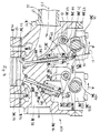
- an internal combustion engine constructed in accordance with this embodiment of the invention is identified generally by the reference numeral 11.
- the engine 11 is shown only partially and in cross section because the invention deals with the valve actuating system for the engine. For this reason, only a portion of a single cylinder of the engine is necessary to understand the construction and operation of the invention. Any details which are not disclosed with respect to the basic structure of the engine may be considered to be conventional.
- the engine 11 is comprised of a cylinder block 12 defining one or more cylinder bores 13 which may have any relationship (in-line, V-type, etc.) and which support pistons 14 for reciprocation.
- the pistons 14 are connected in a well-known manner to connecting rods so as to drive a crankshaft, as is well-known in this art.
- a cylinder head assembly is affixed to the cylinder block 12 in any known manner.
- the cylinder head is is provided with combustion chamber recesses 16 which cooperate with the cylinder bore 13 and pistons 14 so as to form the combustion chambers of the engine.
- One or more intake passages 17 extend through one side of the cylinder head assembly 15 and terminate at valve seats 18 which are pressed or otherwise affixed to the cylinder head 15.
- Poppet-type intake valves 19 cooperate with the valve seats 18 and control the flow through the intake passages 17.
- These intake poppet valve 19 have head portions 21 which open and close engagement with the valve seats 18 and stem portions 22 that are supported for reciprocation within the cylinder head 15 by means of pressed-in valve guides 23.
- a keeper retainer assembly 24 is affixed to the upper end of the intake valve stems 22 and loads a coil compression spring 25 which normally urges the intake valves 19 to their closed positions. The manner in which the intake valves 19 are opened and closed will be described later.
- a suitable induction system (not shown) which includes a manifold having runners 26 is affixed to the intake side of the cylinder head 15 and supplies an air charge flowing as indicated by the arrow 27.
- One or more exhaust passages 28 are formed in the other side of the cylinder head 15 and extend from valve seats 29 which are pressed or otherwise fixed to the cylinder head 15 in communication with the combustion chamber recess 16.
- Poppet-type exhaust valves indicated generally by the reference numeral 31, have head portions 32 that cooperate with the valve seats 29 so as to open and close communication of the combustion chamber cavity 16 with the exhaust passage 28.
- These exhaust valves 31 have their stem portions 33 slidably supported within valve guides 34 that are fixed in a suitable manner to the cylinder head 15.
- Keeper retainer assemblies 35 are affixed to the upper end of the exhaust valve stems 33 and load of coil compression springs 36 which urge the exhaust valves 31 to their closed position.
- the mechanism for opening and closing the exhaust valves 31 as well as the system for opening and closing the intake vales 19 will now be described.
- an intake camshaft 37 and an exhaust camshaft 38 Mounted for rotation in the cylinder head assembly 15 are an intake camshaft 37 and an exhaust camshaft 38.
- the intake and exhaust camshafts 37 and 38 are journalled by respective bearing surfaces formed by the cylinder head 35 and by bearing caps 39 and 41, respectively affixed to the cylinder head 15 along the length of the camshafts 37 and 38. Any known type of bearing system may be employed for the support of the camshafts 37 and 38.
- camshafts 37 and 38 are driven directly from the engine crankshaft at one-half crankshaft speed by any known type of drive mechanism.
- the camshafts 37 and 38 carry a pair of intermeshing gears 42 which effectively drive the non-crankshaft driven camshaft from the crankshaft driven camshaft. Because of the intermeshing gears 42, the camshafts 37 and 38 will rotate in opposite directions from each other as indicated by the arrows A.
- the intake camshaft 37 rotates in a counter-clockwise direction while the exhaust camshaft 38 rotates in a clockwise direction.
- the intake camshaft 38 has cam lobes 43 which, as may be readily apparent from Figure 1, have a generally cylindrical configuration, with their axis offset from the axis of rotation of the intake camshaft 37.
- the cam lobes 43 because of this generally cylindrical configuration, can be easily formed by a grinding operation without requiring special grinding mechanisms or grinding wheels. This is made possible for a reason now to be described.
- Intake rocker arms 44 are pivotally supported on a rocker arm shaft 45 that is mounted to the cylinder head assembly 15 in a known manner, and which defines a pivot axis O.
- These rocker arms 44 carry follower adjusting screws 46 at their outer ends which engage the tips of the intake valve stems 22 for opening and closing these valves 19.
- the follower screws 46 are adjustable, in a known manner, so as to adjust the valve clearance.
- the rocker arms 44 are provided with a follower surface 47 that is disposed between the pivot axis O and a point L1 where the followers 46 contact the valve stems 22.
- the follower surface 47 has a gradually upwardly tapered curved surface as clearly shown in Figure 1 that provides an area which, when contacted by the cam lobe 43, as the camshaft 37 rotates in opening direction will provide a point of contact that moves progressively closer from the heel engagement L2 toward the pivot axis O as shown in Figure 2.
- An exhaust rocker arm 48 is mounted on the exhaust side of the cylinder head 15 upon a rocker arm shaft 49 which is carried by the cylinder head 15 in a known manner.
- the outer end of the exhaust rocker arms 48 carry adjusting follower screws 51 which are engaged with the stems 33 of the exhaust valves 31 for controlling their movement.
- the exhaust camshaft 38 is formed with an exhaust cam lobe 52 which has a configuration similar to the intake cam lobe 43. That is, the exhaust cam lobe 52 is generally a cylindrical configuration and thus can be easily formed by conventional grinding apparatus and grinding wheels, unlike the prior art type of construction.
- the exhaust rocker arms 48 are formed with follower surfaces 53 which are configured so as to provide lever ratio and lift acceleration rate as shown in Figure 2.
- the shape of the rocker arm follower surface 53 is different than the follower surface 47 of the intake rocker arms 44.
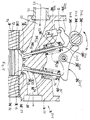
- FIG. 3 Another embodiment of the invention is shown in Figure 3 and the basic components of the engine in this embodiment, which is indicated generally by the reference numeral 101 have the same configuration and construction as the previously described embodiment. For that reason, those components which are the same have been identified by the same reference numerals and will be described again only insofar as is necessary to understand the construction and operation of this embodiment.
- an intake camshaft 102 is rotatably journalled in the cylinder head assembly 15 by a means of bearing cap 103 about a rotational axis that is disposed in the area between the tips of the stems 22 and 33 of the intake and exhaust valves 19 and 31, respectively.
- the intake camshaft 102 has cam lobes 104 which are generally cylindrical in configuration.
- Intake rocker arms are supported for pivotal movement about a pivot axis O by means of an intake rocker arm shaft 106 that is disposed centrally of the cylinder head 15.
- An adjusting screw follower 107 is carried at the outer end of the intake rocker arms 105 and contacts the tips of the valve stems 22 for operating the intake valves 19.
- a follower surface 108 having a configuration similar to the follower surface 53 of the exhaust camshaft 48 of the previously described embodiment is provided and is engaged by the cam lobe 104 so as to provide a varying lever ratio and acceleration curve as shown in Figure 2.
- An exhaust camshaft 109 is supported on the opposite side of the cylinder head 15 but inwardly of the exhaust valves 31 by means of bearing caps 111 in a well-known manner.
- the exhaust camshaft 109 has cam lobe 112 which are generally cylindrical in configuration.
- cam lobes 112 cooperate with exhaust rocker arms 113 that are mounted for pivotal movement about the cylinder head 15 on a rocker arm shaft 114 which is juxtaposed to the intake rocker arm shaft 106. Adjusting screw followers 115 are threaded into the outer ends of the exhaust rocker arms 113 and engage the tips of the exhaust valve stems 33 for their operation.
- a follower surface 116 having a configuration like the intake rocker arm follower surface 47 of the previously described embodiment is positioned between the ends of the exhaust rocker arms 113 and cooperates with the exhaust cam lobe 112 to provide a lever ratio and lift characteristics as shown in Figure 2.
- the intake and exhaust camshafts 102 and 109 carry intermeshing gears 117 so that the camshaft 102 and 109 will rotate in opposite direction.
- the exhaust camshaft 102 rotates in a clockwise direction and the exhaust camshaft 109 rotates in a counter-clockwise direction.
- Any known type of drive may be provided for driving one of the camshafts 102 and 109 in the appropriate direction and at one-half crankshaft speed.
- FIG. 4 An engine constructed in accordance with another embodiment of the invention is shown in Figure 4 and is identified generally by the reference numeral 151.
- This embodiment is similar to the embodiment of Figure 1, but in this embodiment, the intake and exhaust camshafts are driven in such a manner so that they both rotate in the same direction. Because this is the only difference between this embodiment and that of Figure 1, components of this embodiment which are the same as the previously described embodiment of Figure 1 have been identified by the same reference numerals and will not be described again, except insofar as is necessary to understand the construction and operation of this embodiment.
- the exhaust camshaft 152 is rotatably journalled by means of bearing caps 153 and has cam lobes 154 which, like the cam lobes of all of the previously described embodiments, are generally cylindrical. As has been noted, however, in this embodiment, the exhaust camshaft 152 rotates in the same counterclockwise direction as the intake camshaft 37 these rotational directions being shown by the arrows A. As a result of this, an exhaust rocker arm, indicated generally by the reference numeral 155 may be employed which has the same configuration as the intake rocker arm 44.
- This exhaust rocker arm 155 is pivotally supported on an exhaust rocker arm shaft 156 that is carried suitably in the cylinder head but is disposed opposite to the position of the exhaust rocker arm 48 of the embodiment of Figure 1 so as to permit the same configuration to be employed for both intake rocker arm 44 and exhaust rocker arm 155.
- the outer end of the exhaust rocker arms 155 carry adjusting and follower screws 157 that are engaged with the tips of the exhaust valve stems 33 for operating them.
- a follower surface 158 is formed on exhaust rocker arms 155 between the adjusting screws 157 and the rocker arm shaft 156 and has the same shape as the follower surfaces 47 of the intake rocker arms 44 so as to provide the lever ratio and lift curves as shown in Figure 2.
- a single camshaft 202 is rotatably journalled in the cylinder head 15 on the intake side thereof.
- This single camshaft 202 is driven at one-half crankshaft speed by any suitable mechanism and rotates in the direction of the arrow A in Figure 5.
- the camshaft 202 has a plurality of cam lobes 203 that cooperate with intake rocker arms 204 for operating the intake valves 19 and exhaust rocker arms 205 that operate the exhaust valves 31.
- the intake rocker arms 204 are pivotally supported about a pivot axis O on a hydraulic lash adjuster 206 that is mounted in the cylinder head 15 on the intake side of the engine and which is supplied with hydraulic pressure from a suitable source.
- This rocker arm 204 has a tip 207 that is engaged with the tips of the intake valve stems 22 for opening and closing them under the control of the cam lobes 203. It should be noted that since the hydraulic lash adjuster 206 is provided, no adjusting screw is required in this embodiment.
- the rocker arms 204 are provided with follower surfaces 208 that are engaged by the cam lobes 203 and are configured so as to provide acceleration and lever ratio curves as shown in Figure 2.
- the cam lobes 203 are more conventional in having a generally egg shape. However, this can be done without any special grinding techniques or grinding tools, and the configuration of the follower surface 208 provides the desired lift curves.
- the exhaust rocker arm 205 is mounted on a rocker arm shaft 209 that is supported in the cylinder head 15 in any known manner.
- the rocker arm 205 in this embodiment has its pivot axis between its ends, but it is provided with a follower portion 211 which is configured so as to cooperate with one of the cam lobes 203 to again provide a varying lever ratio and lift, as with the other embodiments.
- each intake rocker arm 204 and exhaust rocker arm 205 may cooperate with the same or a different lobe 203 on the camshaft 202.
- the invention may be employed with any number of intake and exhaust valves although the described embodiments have referred to only a single intake valve and a single exhaust valve for each cylinder of the engine.
- the intake valves are all positioned on one side of an axis containing the center of the cylinder bore 13 and the exhaust valves have all been positioned on the other side of this axis.
- the respective camshafts have been disposed on the same side of the axis as their valves which they actuate.
- the camshaft 202 for both the intake and exhaust valves has been disposed on the intake side of the camshaft.
- FIGS. 6 through 8 show a number of embodiments employing multiple valves and these differ from what has already been described only in the valve placement and the flow pattern through the cylinder head. For this reason, these embodiments have employed the same reference numerals so as to indicate corresponding parts from the embodiments as thus far described.
- Figure 6 shows an arrangement embodying two intake valves operated by a common intake camshaft on one side of the cylinder head and a single exhaust valve operated by an exhaust camshaft on the opposite side of the cylinder head.
- the direction of rotation of the camshafts is opposite and they may be in either the direction as shown in Figure 1 or in the direction as shown in Figure 3.
- Figure 7 shows an embodiment wherein one intake valve is positioned on each side of the cylinder bore axis and the exhaust valve is positioned on one aide of the cylinder bore axis. Thus, this provides an intake and exhaust flow as shown by the arrows in this figure.
- one camshaft operates the single intake valve with each cylinder and the other camshaft operates one intake valve and one exhaust valve.
- Figure 8 shows another embodiment having a cross flow pattern with two intake valves and two exhaust valves per cylinder.
- variable valve timing in either the intake and/or exhaust camshaft drive that provides variable valve timing. If this is done, it is not necessary to provide as much overlap as with conventional valve actuating mechanisms due to the fact that the intake and exhaust valves open faster and close slower. Hence, there will be less necessity for using variable valve timing with the described arrangements than with more conventional constructions that are limited by the configuration of the camshaft in conjunction with the valve opening and closing operation.
Landscapes
- Engineering & Computer Science (AREA)
- Mechanical Engineering (AREA)
- General Engineering & Computer Science (AREA)
- Valve-Gear Or Valve Arrangements (AREA)
Applications Claiming Priority (2)
| Application Number | Priority Date | Filing Date | Title |
|---|---|---|---|
| JP4352089A JPH06173619A (ja) | 1992-12-08 | 1992-12-08 | 4サイクルエンジンの動弁機構 |
| JP352089/92 | 1992-12-08 |
Publications (2)
| Publication Number | Publication Date |
|---|---|
| EP0601570A1 true EP0601570A1 (de) | 1994-06-15 |
| EP0601570B1 EP0601570B1 (de) | 1997-10-08 |
Family
ID=18421708
Family Applications (1)
| Application Number | Title | Priority Date | Filing Date |
|---|---|---|---|
| EP93119812A Expired - Lifetime EP0601570B1 (de) | 1992-12-08 | 1993-12-08 | Ventiltrieb für Brennkraftmaschine |
Country Status (4)
| Country | Link |
|---|---|
| US (2) | US5427065A (de) |
| EP (1) | EP0601570B1 (de) |
| JP (1) | JPH06173619A (de) |
| DE (1) | DE69314439T2 (de) |
Cited By (3)
| Publication number | Priority date | Publication date | Assignee | Title |
|---|---|---|---|---|
| EP0692613A1 (de) * | 1994-06-17 | 1996-01-17 | Yamaha Hatsudoki Kabushiki Kaisha | Brennkraftmaschine und Verfahren zum Zuführen von Luft zum Brennraum einer Brennkraftmaschine |
| WO1997014879A1 (en) * | 1995-10-17 | 1997-04-24 | C.R.F. Societa' Consortile Per Azioni | Internal combustion diesel engine for motor-vehicles, with direct injection |
| WO2009007141A1 (en) * | 2007-07-06 | 2009-01-15 | Brp-Rotax Gmbh & Co. Kg | Internal combustion engine cam follower arrangement |
Families Citing this family (14)
| Publication number | Priority date | Publication date | Assignee | Title |
|---|---|---|---|---|
| JPH06173619A (ja) * | 1992-12-08 | 1994-06-21 | Yamaha Motor Co Ltd | 4サイクルエンジンの動弁機構 |
| EP0967367B1 (de) * | 1998-06-24 | 2003-12-03 | Yamaha Hatsudoki Kabushiki Kaisha | Ventilsteuerungseinrichtung für eine Brennkraftmaschine |
| JP2000120413A (ja) * | 1998-10-12 | 2000-04-25 | Isuzu Motors Ltd | 多弁式dohcエンジンのバルブ駆動機構 |
| US6543401B2 (en) * | 2001-08-31 | 2003-04-08 | American Spares & Repairs Pty., Ltd. | Camshaft drive mechanism |
| EP1592868A4 (de) * | 2003-02-14 | 2008-10-15 | Jesel Inc | Ventiltrieb und nockennase |
| CN101012760A (zh) * | 2007-02-14 | 2007-08-08 | 无锡东南车辆科技有限公司 | 顶置式凸轮发动机 |
| US20090272365A1 (en) * | 2008-04-30 | 2009-11-05 | Kunz Timothy W | Cam lobe profile for driving a mechanical fuel pump |
| US20110226200A1 (en) * | 2010-03-22 | 2011-09-22 | Trease John M | Axial float plate |
| JP2013144941A (ja) * | 2012-01-13 | 2013-07-25 | Suzuki Motor Corp | 内燃機関の動弁装置 |
| JP6118057B2 (ja) * | 2012-09-28 | 2017-04-19 | 本田技研工業株式会社 | 4ストローク内燃機関のロッカー軸配置構造 |
| US9915222B2 (en) * | 2014-03-26 | 2018-03-13 | Cummins Inc. | Diesel piston with semi-hemispherical crown |
| JP6349425B2 (ja) * | 2017-02-15 | 2018-06-27 | 本田技研工業株式会社 | 4ストローク内燃機関のロッカー軸配置構造 |
| US20200131950A1 (en) * | 2018-10-24 | 2020-04-30 | Honda Motor Co., Ltd. | Methods of setting a tappet in an engine |
| WO2020227779A1 (en) * | 2019-05-15 | 2020-11-19 | Kenneth David Burrows | A valve control assembly |
Citations (8)
| Publication number | Priority date | Publication date | Assignee | Title |
|---|---|---|---|---|
| DE843329C (de) * | 1950-09-20 | 1952-07-07 | Daimler Benz Ag | Ventilsteuerung fuer Brennkraftmaschinen |
| DE2809915A1 (de) * | 1978-03-08 | 1979-09-13 | Maschf Augsburg Nuernberg Ag | Nocken zur steuerung der ventile in hubkolbenmaschinen |
| FR2552820A1 (fr) * | 1983-10-04 | 1985-04-05 | Honda Motor Co Ltd | Culasse de cylindre pour moteur a combustion interne du type a double arbre a cames en tete |
| US4617881A (en) * | 1985-03-29 | 1986-10-21 | Yamaha Hatsudoki Kabushiki Kaisha | Actuating mechanism for multiple valve internal combustion engine |
| EP0333416A1 (de) * | 1988-03-18 | 1989-09-20 | Honda Giken Kogyo Kabushiki Kaisha | Ventiltriebvorrichtung für Brennkraftmaschine |
| US4969427A (en) * | 1988-03-31 | 1990-11-13 | Suzuki Jidosha Kogyo Kabushiki Kaisha | Cylinder head of a four-cycle engine |
| EP0453416A1 (de) * | 1990-04-20 | 1991-10-23 | FIAT AUTO S.p.A. | Brennkraftmaschine für motorisiertes Fahrzeug mit in verschiedener Weise geöffneten Ventilen |
| DE4121504A1 (de) * | 1990-09-13 | 1992-03-26 | Skoda Automobilova | Zylinderkopf |
Family Cites Families (15)
| Publication number | Priority date | Publication date | Assignee | Title |
|---|---|---|---|---|
| US4438737A (en) * | 1981-10-13 | 1984-03-27 | Investment Rarities, Incorporated | Apparatus and method for controlling the valve operation of an internal combustion engine |
| JPS5943911A (ja) * | 1982-09-03 | 1984-03-12 | Toyota Motor Corp | 内燃機関用カム |
| EP0286389A3 (de) * | 1987-04-07 | 1989-02-15 | The British Internal Combustion Engine Research Institute Limited | Vorrichtung zum Regeln der Steuerzeit eines Ventils |
| JPH0658047B2 (ja) * | 1988-06-14 | 1994-08-03 | 本田技研工業株式会社 | 内燃機関の動弁制御装置 |
| JPH0621531B2 (ja) * | 1988-12-28 | 1994-03-23 | いすゞ自動車株式会社 | 電磁力駆動バルブの制御装置 |
| JPH086568B2 (ja) * | 1989-04-13 | 1996-01-24 | 日産自動車株式会社 | エンジンの弁作動制御装置 |
| JPH0337308A (ja) * | 1989-06-30 | 1991-02-18 | Mazda Motor Corp | Dohcエンジンの動弁装置 |
| EP0420290B1 (de) * | 1989-09-29 | 1994-03-30 | Mazda Motor Corporation | Ventiltriebvorrichtung für Brennkraftmaschine |
| FR2659388A1 (fr) * | 1990-03-07 | 1991-09-13 | Barbotte Michel | Dispositif de commande variable des soupapes d'un moteur a combustion. |
| US4974560A (en) * | 1990-03-21 | 1990-12-04 | King Brian T | Mechanism for varying valve duration in an internal combustion engine |
| EP0458341A1 (de) * | 1990-05-24 | 1991-11-27 | Mazda Motor Corporation | Zylinderkopf eines Doppelnockenwellenmotors |
| US5269267A (en) * | 1991-04-25 | 1993-12-14 | Gerald Beaumont | Mechanism for controlling valve timing |
| US5216988A (en) * | 1992-10-15 | 1993-06-08 | Siemens Automotive L.P. | Dual bucket hydraulic actuator |
| JPH06173619A (ja) * | 1992-12-08 | 1994-06-21 | Yamaha Motor Co Ltd | 4サイクルエンジンの動弁機構 |
| US5327856A (en) * | 1992-12-22 | 1994-07-12 | General Motors Corporation | Method and apparatus for electrically driving engine valves |
-
1992
- 1992-12-08 JP JP4352089A patent/JPH06173619A/ja active Pending
-
1993
- 1993-12-08 US US08/170,061 patent/US5427065A/en not_active Expired - Lifetime
- 1993-12-08 DE DE69314439T patent/DE69314439T2/de not_active Expired - Fee Related
- 1993-12-08 EP EP93119812A patent/EP0601570B1/de not_active Expired - Lifetime
-
1996
- 1996-09-19 US US08/718,170 patent/US5752479A/en not_active Expired - Fee Related
Patent Citations (8)
| Publication number | Priority date | Publication date | Assignee | Title |
|---|---|---|---|---|
| DE843329C (de) * | 1950-09-20 | 1952-07-07 | Daimler Benz Ag | Ventilsteuerung fuer Brennkraftmaschinen |
| DE2809915A1 (de) * | 1978-03-08 | 1979-09-13 | Maschf Augsburg Nuernberg Ag | Nocken zur steuerung der ventile in hubkolbenmaschinen |
| FR2552820A1 (fr) * | 1983-10-04 | 1985-04-05 | Honda Motor Co Ltd | Culasse de cylindre pour moteur a combustion interne du type a double arbre a cames en tete |
| US4617881A (en) * | 1985-03-29 | 1986-10-21 | Yamaha Hatsudoki Kabushiki Kaisha | Actuating mechanism for multiple valve internal combustion engine |
| EP0333416A1 (de) * | 1988-03-18 | 1989-09-20 | Honda Giken Kogyo Kabushiki Kaisha | Ventiltriebvorrichtung für Brennkraftmaschine |
| US4969427A (en) * | 1988-03-31 | 1990-11-13 | Suzuki Jidosha Kogyo Kabushiki Kaisha | Cylinder head of a four-cycle engine |
| EP0453416A1 (de) * | 1990-04-20 | 1991-10-23 | FIAT AUTO S.p.A. | Brennkraftmaschine für motorisiertes Fahrzeug mit in verschiedener Weise geöffneten Ventilen |
| DE4121504A1 (de) * | 1990-09-13 | 1992-03-26 | Skoda Automobilova | Zylinderkopf |
Cited By (6)
| Publication number | Priority date | Publication date | Assignee | Title |
|---|---|---|---|---|
| EP0692613A1 (de) * | 1994-06-17 | 1996-01-17 | Yamaha Hatsudoki Kabushiki Kaisha | Brennkraftmaschine und Verfahren zum Zuführen von Luft zum Brennraum einer Brennkraftmaschine |
| US5606942A (en) * | 1994-06-17 | 1997-03-04 | Yamaha Hatsudoki Kabushiki Kaisha | Valve operating system for multi-valve engine |
| WO1997014879A1 (en) * | 1995-10-17 | 1997-04-24 | C.R.F. Societa' Consortile Per Azioni | Internal combustion diesel engine for motor-vehicles, with direct injection |
| WO2009007141A1 (en) * | 2007-07-06 | 2009-01-15 | Brp-Rotax Gmbh & Co. Kg | Internal combustion engine cam follower arrangement |
| WO2009007142A1 (en) * | 2007-07-06 | 2009-01-15 | Brp-Rotax Gmbh & Co. Kg | Internal combustion engine cylinder head assembly |
| US7845323B2 (en) | 2007-07-06 | 2010-12-07 | Brp-Powertrain Gmbh & Co Kg | Internal combustion engine cam follower arrangement |
Also Published As
| Publication number | Publication date |
|---|---|
| DE69314439T2 (de) | 1998-02-05 |
| US5427065A (en) | 1995-06-27 |
| JPH06173619A (ja) | 1994-06-21 |
| EP0601570B1 (de) | 1997-10-08 |
| US5752479A (en) | 1998-05-19 |
| DE69314439D1 (de) | 1997-11-13 |
Similar Documents
| Publication | Publication Date | Title |
|---|---|---|
| US6357405B1 (en) | Valve drive mechanism of four-stroke cycle engine | |
| US5785017A (en) | Variable valve timing mechanism | |
| EP0601570B1 (de) | Ventiltrieb für Brennkraftmaschine | |
| US5606942A (en) | Valve operating system for multi-valve engine | |
| JP2810442B2 (ja) | エンジンの弁作動装置 | |
| US4624222A (en) | Intake valve structure for internal combustion engine | |
| USRE33787E (en) | Four-cycle engine | |
| US4539953A (en) | Apparatus for actuating intake and exhaust valves in internal combustion engine | |
| EP0213759A1 (de) | Ventilantriebsmechanismus | |
| US5813377A (en) | Engine valve operating system | |
| US6170449B1 (en) | Valve operating system for engine | |
| US5253620A (en) | Internal combustion engine adjustable valve gear | |
| US4638774A (en) | Valve actuating mechanism for internal combustion engine | |
| EP0963508B1 (de) | Stellvorrichtung für ventile | |
| US6481397B2 (en) | Variable valve drive system for an internal combustion engine | |
| US4637356A (en) | Valve actuating mechanism for internal combustion engine | |
| US5245957A (en) | Spring assist system for internal combustion engine valves | |
| US6360705B1 (en) | Mechanism for variable valve lift and cylinder deactivation | |
| US5560329A (en) | Valvetrain for a pushrod engine | |
| EP3667037B1 (de) | Ventiltrieb mit schaltbarer motorbremsung | |
| US4773360A (en) | Internal combustion engine | |
| US4915065A (en) | Valve actuation device for multi-valve type engine | |
| US4495902A (en) | Mechanism for variably controlling an internal combustion engine valve | |
| JPH10121925A (ja) | 内燃機関用バルブ駆動装置 | |
| JP2607763B2 (ja) | シリンダに多数のバルブを具備した特に内燃機関用タイミング機構 |
Legal Events
| Date | Code | Title | Description |
|---|---|---|---|
| PUAI | Public reference made under article 153(3) epc to a published international application that has entered the european phase |
Free format text: ORIGINAL CODE: 0009012 |
|
| AK | Designated contracting states |
Kind code of ref document: A1 Designated state(s): DE FR GB IT |
|
| 17P | Request for examination filed |
Effective date: 19941208 |
|
| 17Q | First examination report despatched |
Effective date: 19950126 |
|
| GRAG | Despatch of communication of intention to grant |
Free format text: ORIGINAL CODE: EPIDOS AGRA |
|
| GRAH | Despatch of communication of intention to grant a patent |
Free format text: ORIGINAL CODE: EPIDOS IGRA |
|
| GRAH | Despatch of communication of intention to grant a patent |
Free format text: ORIGINAL CODE: EPIDOS IGRA |
|
| GRAH | Despatch of communication of intention to grant a patent |
Free format text: ORIGINAL CODE: EPIDOS IGRA |
|
| GRAA | (expected) grant |
Free format text: ORIGINAL CODE: 0009210 |
|
| AK | Designated contracting states |
Kind code of ref document: B1 Designated state(s): DE FR GB IT |
|
| PG25 | Lapsed in a contracting state [announced via postgrant information from national office to epo] |
Ref country code: FR Free format text: LAPSE BECAUSE OF FAILURE TO SUBMIT A TRANSLATION OF THE DESCRIPTION OR TO PAY THE FEE WITHIN THE PRESCRIBED TIME-LIMIT Effective date: 19971008 |
|
| REF | Corresponds to: |
Ref document number: 69314439 Country of ref document: DE Date of ref document: 19971113 |
|
| ITF | It: translation for a ep patent filed | ||
| EN | Fr: translation not filed | ||
| PLBE | No opposition filed within time limit |
Free format text: ORIGINAL CODE: 0009261 |
|
| STAA | Information on the status of an ep patent application or granted ep patent |
Free format text: STATUS: NO OPPOSITION FILED WITHIN TIME LIMIT |
|
| 26N | No opposition filed | ||
| REG | Reference to a national code |
Ref country code: GB Ref legal event code: IF02 |
|
| PGFP | Annual fee paid to national office [announced via postgrant information from national office to epo] |
Ref country code: GB Payment date: 20021204 Year of fee payment: 10 |
|
| PG25 | Lapsed in a contracting state [announced via postgrant information from national office to epo] |
Ref country code: GB Free format text: LAPSE BECAUSE OF NON-PAYMENT OF DUE FEES Effective date: 20031208 |
|
| GBPC | Gb: european patent ceased through non-payment of renewal fee |
Effective date: 20031208 |
|
| PGFP | Annual fee paid to national office [announced via postgrant information from national office to epo] |
Ref country code: DE Payment date: 20081205 Year of fee payment: 16 |
|
| PGFP | Annual fee paid to national office [announced via postgrant information from national office to epo] |
Ref country code: IT Payment date: 20081229 Year of fee payment: 16 |
|
| PG25 | Lapsed in a contracting state [announced via postgrant information from national office to epo] |
Ref country code: DE Free format text: LAPSE BECAUSE OF NON-PAYMENT OF DUE FEES Effective date: 20100701 |
|
| PG25 | Lapsed in a contracting state [announced via postgrant information from national office to epo] |
Ref country code: IT Free format text: LAPSE BECAUSE OF NON-PAYMENT OF DUE FEES Effective date: 20091208 |