EP0600398A1 - Fahrzeugluftreifen mit asymmetrischen Gürteleigenschaften - Google Patents
Fahrzeugluftreifen mit asymmetrischen Gürteleigenschaften Download PDFInfo
- Publication number
- EP0600398A1 EP0600398A1 EP93119142A EP93119142A EP0600398A1 EP 0600398 A1 EP0600398 A1 EP 0600398A1 EP 93119142 A EP93119142 A EP 93119142A EP 93119142 A EP93119142 A EP 93119142A EP 0600398 A1 EP0600398 A1 EP 0600398A1
- Authority
- EP
- European Patent Office
- Prior art keywords
- tire
- bandages
- pneumatic vehicle
- bandage
- tire according
- Prior art date
- Legal status (The legal status is an assumption and is not a legal conclusion. Google has not performed a legal analysis and makes no representation as to the accuracy of the status listed.)
- Granted
Links
Images

Classifications
-
- B—PERFORMING OPERATIONS; TRANSPORTING
- B60—VEHICLES IN GENERAL
- B60C—VEHICLE TYRES; TYRE INFLATION; TYRE CHANGING; CONNECTING VALVES TO INFLATABLE ELASTIC BODIES IN GENERAL; DEVICES OR ARRANGEMENTS RELATED TO TYRES
- B60C9/00—Reinforcements or ply arrangement of pneumatic tyres
- B60C9/18—Structure or arrangement of belts or breakers, crown-reinforcing or cushioning layers
- B60C9/30—Structure or arrangement of belts or breakers, crown-reinforcing or cushioning layers asymmetric to the midcircumferential plane of the tyre
-
- B—PERFORMING OPERATIONS; TRANSPORTING
- B60—VEHICLES IN GENERAL
- B60C—VEHICLE TYRES; TYRE INFLATION; TYRE CHANGING; CONNECTING VALVES TO INFLATABLE ELASTIC BODIES IN GENERAL; DEVICES OR ARRANGEMENTS RELATED TO TYRES
- B60C9/00—Reinforcements or ply arrangement of pneumatic tyres
- B60C9/18—Structure or arrangement of belts or breakers, crown-reinforcing or cushioning layers
- B60C9/20—Structure or arrangement of belts or breakers, crown-reinforcing or cushioning layers built-up from rubberised plies each having all cords arranged substantially parallel
- B60C9/2003—Structure or arrangement of belts or breakers, crown-reinforcing or cushioning layers built-up from rubberised plies each having all cords arranged substantially parallel characterised by the materials of the belt cords
- B60C9/2009—Structure or arrangement of belts or breakers, crown-reinforcing or cushioning layers built-up from rubberised plies each having all cords arranged substantially parallel characterised by the materials of the belt cords comprising plies of different materials
-
- B—PERFORMING OPERATIONS; TRANSPORTING
- B60—VEHICLES IN GENERAL
- B60C—VEHICLE TYRES; TYRE INFLATION; TYRE CHANGING; CONNECTING VALVES TO INFLATABLE ELASTIC BODIES IN GENERAL; DEVICES OR ARRANGEMENTS RELATED TO TYRES
- B60C9/00—Reinforcements or ply arrangement of pneumatic tyres
- B60C9/18—Structure or arrangement of belts or breakers, crown-reinforcing or cushioning layers
- B60C9/20—Structure or arrangement of belts or breakers, crown-reinforcing or cushioning layers built-up from rubberised plies each having all cords arranged substantially parallel
- B60C9/22—Structure or arrangement of belts or breakers, crown-reinforcing or cushioning layers built-up from rubberised plies each having all cords arranged substantially parallel the plies being arranged with all cords disposed along the circumference of the tyre
- B60C9/2204—Structure or arrangement of belts or breakers, crown-reinforcing or cushioning layers built-up from rubberised plies each having all cords arranged substantially parallel the plies being arranged with all cords disposed along the circumference of the tyre obtained by circumferentially narrow strip winding
-
- B—PERFORMING OPERATIONS; TRANSPORTING
- B60—VEHICLES IN GENERAL
- B60C—VEHICLE TYRES; TYRE INFLATION; TYRE CHANGING; CONNECTING VALVES TO INFLATABLE ELASTIC BODIES IN GENERAL; DEVICES OR ARRANGEMENTS RELATED TO TYRES
- B60C9/00—Reinforcements or ply arrangement of pneumatic tyres
- B60C9/18—Structure or arrangement of belts or breakers, crown-reinforcing or cushioning layers
- B60C9/26—Folded plies
-
- B—PERFORMING OPERATIONS; TRANSPORTING
- B60—VEHICLES IN GENERAL
- B60C—VEHICLE TYRES; TYRE INFLATION; TYRE CHANGING; CONNECTING VALVES TO INFLATABLE ELASTIC BODIES IN GENERAL; DEVICES OR ARRANGEMENTS RELATED TO TYRES
- B60C9/00—Reinforcements or ply arrangement of pneumatic tyres
- B60C9/18—Structure or arrangement of belts or breakers, crown-reinforcing or cushioning layers
- B60C9/20—Structure or arrangement of belts or breakers, crown-reinforcing or cushioning layers built-up from rubberised plies each having all cords arranged substantially parallel
- B60C9/22—Structure or arrangement of belts or breakers, crown-reinforcing or cushioning layers built-up from rubberised plies each having all cords arranged substantially parallel the plies being arranged with all cords disposed along the circumference of the tyre
- B60C9/2204—Structure or arrangement of belts or breakers, crown-reinforcing or cushioning layers built-up from rubberised plies each having all cords arranged substantially parallel the plies being arranged with all cords disposed along the circumference of the tyre obtained by circumferentially narrow strip winding
- B60C2009/2209—Structure or arrangement of belts or breakers, crown-reinforcing or cushioning layers built-up from rubberised plies each having all cords arranged substantially parallel the plies being arranged with all cords disposed along the circumference of the tyre obtained by circumferentially narrow strip winding characterised by tension of the cord during winding
-
- B—PERFORMING OPERATIONS; TRANSPORTING
- B60—VEHICLES IN GENERAL
- B60C—VEHICLE TYRES; TYRE INFLATION; TYRE CHANGING; CONNECTING VALVES TO INFLATABLE ELASTIC BODIES IN GENERAL; DEVICES OR ARRANGEMENTS RELATED TO TYRES
- B60C9/00—Reinforcements or ply arrangement of pneumatic tyres
- B60C9/18—Structure or arrangement of belts or breakers, crown-reinforcing or cushioning layers
- B60C9/20—Structure or arrangement of belts or breakers, crown-reinforcing or cushioning layers built-up from rubberised plies each having all cords arranged substantially parallel
- B60C9/22—Structure or arrangement of belts or breakers, crown-reinforcing or cushioning layers built-up from rubberised plies each having all cords arranged substantially parallel the plies being arranged with all cords disposed along the circumference of the tyre
- B60C2009/2219—Structure or arrangement of belts or breakers, crown-reinforcing or cushioning layers built-up from rubberised plies each having all cords arranged substantially parallel the plies being arranged with all cords disposed along the circumference of the tyre with a partial zero degree ply at the belt edges - edge band
-
- B—PERFORMING OPERATIONS; TRANSPORTING
- B60—VEHICLES IN GENERAL
- B60C—VEHICLE TYRES; TYRE INFLATION; TYRE CHANGING; CONNECTING VALVES TO INFLATABLE ELASTIC BODIES IN GENERAL; DEVICES OR ARRANGEMENTS RELATED TO TYRES
- B60C9/00—Reinforcements or ply arrangement of pneumatic tyres
- B60C9/18—Structure or arrangement of belts or breakers, crown-reinforcing or cushioning layers
- B60C9/20—Structure or arrangement of belts or breakers, crown-reinforcing or cushioning layers built-up from rubberised plies each having all cords arranged substantially parallel
- B60C9/22—Structure or arrangement of belts or breakers, crown-reinforcing or cushioning layers built-up from rubberised plies each having all cords arranged substantially parallel the plies being arranged with all cords disposed along the circumference of the tyre
- B60C2009/2223—Structure or arrangement of belts or breakers, crown-reinforcing or cushioning layers built-up from rubberised plies each having all cords arranged substantially parallel the plies being arranged with all cords disposed along the circumference of the tyre with an interrupted zero degree ply, e.g. using two or more portions for the same ply
-
- B—PERFORMING OPERATIONS; TRANSPORTING
- B60—VEHICLES IN GENERAL
- B60C—VEHICLE TYRES; TYRE INFLATION; TYRE CHANGING; CONNECTING VALVES TO INFLATABLE ELASTIC BODIES IN GENERAL; DEVICES OR ARRANGEMENTS RELATED TO TYRES
- B60C9/00—Reinforcements or ply arrangement of pneumatic tyres
- B60C9/18—Structure or arrangement of belts or breakers, crown-reinforcing or cushioning layers
- B60C9/20—Structure or arrangement of belts or breakers, crown-reinforcing or cushioning layers built-up from rubberised plies each having all cords arranged substantially parallel
- B60C9/22—Structure or arrangement of belts or breakers, crown-reinforcing or cushioning layers built-up from rubberised plies each having all cords arranged substantially parallel the plies being arranged with all cords disposed along the circumference of the tyre
- B60C2009/2252—Physical properties or dimension of the zero degree ply cords
- B60C2009/2295—Physical properties or dimension of the zero degree ply cords with different cords in the same layer
Definitions
- the invention relates to a pneumatic pneumatic vehicle tire with a belt-reinforced tread, in which the belt additionally has a bandage cover layer made of reinforcing elements, which consists of textile cord or thread materials that shorten under the effect of heat and is present radially on the outside of the belt.
- the aim of the invention is to realize the different tension states for the tire crown and shoulder area, in order to enable bandaging of the belt in a simple and inexpensive manner and ultimately to obtain a radial belt tire for high-speed suitability, which with respect to the tire weight, the Rolling resistance and low tendency to flatten at rest is improved.
- the belt is to be bandaged and stabilized in such a way that a substantially balanced tension is present in the tire center area and in the tire shoulder areas when driving, essentially over the belt width.
- Constructive examples of the use of bandage materials for asymmetrical belt constructions can be: Outer shoulder Tire center Inner shoulder Mat. Constr. epdm Mat. Constr. epdm Mat. Constr. epdm Mat. Constr. epdm nylon 1400/2 no matter nylon 940/2 no matter nylon 1400/1 no matter Rayon 1840/2 no matter polyester 1440/1 no matter nylon 940/1 no matter Aramid 1670/2 no matter nylon 1440/2 no matter Rayon 1840/1 no matter nylon 720/2 no matter Rayon 1220/2 no matter Aramid 840/1 no matter polyester 1100/2 no matter Aramid 1670/1 no matter nylon 940/2 no matter nylon 1400/1 no matter Rayon 1840/2 no matter nylon 1400/2 no matter Rayon 1220/2 no matter Rayon 1840/2 no matter Rayon 1220/1 no matter nylon 1400/1 x nylon 1400/1 y nylon 1400/1 e.g. nylon 1400/1 x Rayon 1840/2 no matter nylon 1400/1 y Rayon
- x, y and z are not the same size.
- the difference between the values is greater than or equal to 10%.
- the asymmetry of the belt structure is therefore essentially determined by the use of different bandage materials and / or different packing densities (epdm) with the same textile cord materials.
- the width of the individual bandages can be composed of narrow individual bandages (from a minimum width of 3 mm).
- the bandages are primarily aligned according to the tire circumference and the cord material forms an angle between 0 ° and 30 ° with the tire circumference, whereby the different bandage sections (outer shoulder, inner shoulder, center of the tire) can differ in their angle.
- Another advantage of the radial radial tire which has separate bandages made of different reinforcing element materials, for example selected from polyamide, polyester, rayon, aromatic polyamide or carbon fibers, is that low-flat materials are used which have the property of flattening when the tire is warm (flatspotting). reduce considerably if such flat-spot-poor materials can be used for the reinforcing elements.
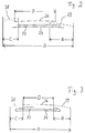
- the pneumatic vehicle tire which is essentially constructed from rubber or rubber-like plastics, has a carcass, preferably a radial carcass 2, which is anchored in the beads 4 by looping around tensile bead cores 6.
- a conventional reinforcing belt 10 between it and the tread 8, which can consist, for example, of two steel cord plies arranged in a cross structure.
- the belt 10 is surrounded radially on the outside by cover bandages 12, 14, 16, which together cover the belt in its full width.
- cover bandages 12, 14, 16 which together cover the belt in its full width.
- aramid cord can also be used for belt 10 or a reinforcement made of carbon fibers can be provided.
- This belt 10 is provided with separate bandages 12 for the tire center area and 14 and 16 for the respective tire shoulder area.
- the total width of the belt bandage and bandages is labeled A.
- the width of the bandage 12 present in the middle bears the reference symbol D.
- the widths of the two shoulder bandages 14 and 16 are denoted by B and C. All bandages can be arranged symmetrically to the tire center line xx. But it is also possible to arrange the bandages in any asymmetry to the tire center line xx.
- the bandages can be in the form of winding bandages. But you can also in the production process as an individual Strips are placed.
- the width C of the shoulder bandage 14, arranged towards the outside of the tire is preferably 5% to 45% of the total width A.
- the width B of the other shoulder bandage 16, which is arranged more towards the inside of the tire, is likewise preferably 5% to 45% of the total width A.
- the preferred width D is 10% to 90% of the total width A.
- Their width D is then 0% of the total width A.
- the widths C and D of the shoulder bandages 14 and 16 can then be up to 50% of the total width A.
- the materials for the reinforcement elements of the bandages are different. The differences result in different stress states in the reinforcement elements during the production of the tire under pressure and heat.
- the middle covering bandage 26 with the width D covers the radially outer reinforcement layer 22 on the outside of the tire over the reinforcement outer edge, while it ends on the inside of the tire in front of the reinforcement layer edge.
- the cover bandage 28 is present twice on the outside of the tire with the same width C.
- the covering bandage 28 lies radially outside of the middle covering bandage 26 and partially overlaps it.
- a simple cover layer 29 with the width B is provided, which is arranged radially within the middle cover layer 26 and is partially covered by it.
- the ratios of the widths A, B, C, D to one another are in the same order of magnitude as in FIG. 1.
- FIG. 3 now shows an arrangement in which a second, folded and essentially radially inner reinforcement layer 34 is wrapped asymmetrically about the tire center line around a first, radially outer reinforcement layer 32.
- the length of the envelope on the outside of the tire is greater than the length of the envelope on the inside of the tire.
- the tire center bandage 36 has a width D symmetrical to the tire center plane xx.
- the tire side bandage 38 is arranged on the outside of the tire with the width C and the tire side bandage 39 is provided on the inside of the tire with the width B, with all bandages made of different Can consist of materials or of the same materials with different characteristics.
- the three different bandages lie side by side on the same plane in a radial view and do not overlap.
- the ratios of the widths to one another are in the same order of magnitude as in FIG. 1.
- the reinforcing elements in each strip are arranged essentially parallel to one another. Their distance is approximately the reinforcement element thickness.
- the combination bandage ensures that the tensions across the belt width are compensated favorably, that good tire rolling resistance values are obtained solely with the means of different reinforcing element materials, and that the overall flattening behavior of the tire is considerably improved due to the defined but selectable materials.
- the tire with belt and bandages made of different materials maintains a high level of uniformity and essentially maintains this even in the idle state after use as a high-speed wide tire.
- the edges of the belt which tend to increase in diameter when the speed is high, are held firmly bandaged in the predetermined tension range by the side bandages.
- the center bandage essentially absorbs the belt tension from the radial elevation during the vulcanization and tension of the post-vulcanization and essentially keeps the tension from the radial and circumferential forces evenly distributed over the belt width during high-speed operation, whereby it is effectively supported by the edge bandages.
- a targeted belt strength with strength gradation across belt width can be obtained in a simple and cost-saving construction to achieve the intended goals. Due to the proposed different material use, a specific strength gradation across the belt width can be achieved. It depends solely on the coordinated selection of materials and the selected cord constructions for the reinforcement elements of the bandages. Spooling bandages, for example, are only put on with a specific, selectable winding tension, and additional measures and means for regulating and controlling any winding devices are not required to adjust the tension conditions across the belt width.
Abstract
Description
- Die Erfindung bezieht sich auf einen Fahrzeugluftreifen in Radialbauart mit einem gürtelverstärkten Laufstreifen, bei dem der Gürtel zusätzlich eine Bandagenabdecklage aus Verstärkungselementen aufweist, die aus unter Wärmeeinwirkung sich verkürzenden textilen Kord- oder Fadenmaterialien besteht und radial außen auf dem Gürtel vorliegt.
- Bei Fahrzeugluftreifen ist es nach DE-OS 2 853 001 bekannt, den Gürtelverband, der bevorzugt aus ein oder zwei Lagen, letztere dabei in zueinander gekreuzter Anordnung, besteht, durch eine Abdecklage oder Abdeckstreifen zu bandagieren und zu stabilisieren. Bevorzugt werden dazu Korde oder Einfachgarne verwendet, die aus Polyamid oder Polyester bestehen und sich unter Wärmeeinwirkung verkürzen. Der Modul dieser Elemente ist verhältnismäßig groß. Bei der Reifenfertigung unter Druck und Wärme liegen die Verstärkungselemente dabei mit verhältnismäßig großer Spannung vor. Die Spannungen sind über Gürtelbreite gesehen nicht gleich. Insoweit können Verzerrungen im Laufstreifenbereich entstehen, die die Reifengleichförmigkeit (uniformity) beeinflussen. Bei der Reifenherstellung unter Druck und Wärme, insbesondere bei der Vulkanisation und Nachvulkanisation, ergibt sich ein radiales Wachstum, das als Erhebung bekannt ist und in der Regel 2 % bis 4 % beträgt. Die Entspannung des Gürtels durch die bandagenförmige Abdecklage liegt in etwa in der gleichen Größenordnung von 2 % bis 4 %.
- Die Gebrauchseigenschaften von Fahrzeugluftreifen haben generell einen hohen technischen Stand erreicht. Ein weiterer Technologiesprung für diese in der Regel symmetrisch aufgebauten Reifen ist nur noch möglich durch Nutzung von asymmetrischen Elementen.
- Asymmetrisch aufgebaute Reifen haben den Vorteil, daß die Außen- und Innenschulter der Reifen (fahrzeugseitig gesehen) je nach Anwendungsfall unterschiedliche Aufgaben erfüllen müssen. Hier liegt also noch ein Anwendungsfeld, durch asymmetrische Reifenaufbauten diesem Anforderungsprofil optimaler zu entsprechen. Beispiele für Anforderungen, welche durch asymmetrische Reifenkonstruktionen günstiger optimiert werden können sind:
- sportliches Fahrverhalten belastet besonders die Reifenaußenschulter,
- Fahrzeugsturz belastet besonders die Reifeninnenseite,
- das Vorbeifahrgeräusch (nach ISO 362) wird insbesondere durch die Druck- und Schlupfverhältnisse der Reifenmitte und/oder die Reifenschultern beeinflußt, je nach Massenverteilung des Laufflächenprofils kann das Reifenumfangswachstum besser durch asymmetrische Gürtelkonstruktionen unter Kontrolle gehalten werden.
Dies ist besonders für Fahrzeuge wichtig, die geschwindigkeitsabgeregelt sind und/oder mit Antiblockier- und/oder Antischlupfsystemen ausgestattet sind. - Fahrzeugreifen sind je nach ihrer Radposition unterschiedlichen Belastungen ausgesetzt, die sich insbesondere im Bereich der beiden Gürtelkanten äußern. So wird bei Kurvenfahrt der Schulterbereich auf der dem Fahrzeug abgewandten Seite des Fahrzeugluftreifens stärker belastet als auf der Innenseite. Somit ist es wünschenswert, im Bereich der äußeren Schulterkante eine zusätzliche Verstärkung vorzusehen. Bei Vorspur und größerer Reifenkonizität als negativem Sturz ergibt sich die schon beschriebene Asymmetrie der Belastung schon bei der Geradeausfahrt.
- Einige Reifenhersteller bieten deshalb schon Reifen mit asymmetrischen Merkmalen an.
- Ziel der Erfindung ist es, die für den Reifenkronen- und Reifenschulterbereich unterschiedlichen Spannungszustände zu verwirklichen, um eine Bandagierung des Gürtels auf einfache und kostengünstige Art und Weise zu ermöglichen und um letztendlich einen Gürtelradialreifen für Hochgeschwindigkeitseignung zu erhalten, der in bezug auf das Reifengewicht, den Rollwiderstand sowie geringe Neigung zur Abflachung im Ruhezustand verbessert ist. Der Gürtel soll so durch eine Abdecklage bandagiert und stabilisiert werden, daß im wesentlichen über Gürtelbreite gesehen im Reifenmittenbereich und in den Reifenschulterbereichen im Fahrbetrieb eine im wesentlichen ausgeglichene Spannung vorliegt.
- Ein weiteres Ziel der vorliegenden Erfindung ist es, daß profilunterstützend eine asymmetrische Gürtelkonstruktion angewandt wird, wobei die Asymmetrie sich auf eine dreigeteilte Bandage bezieht gekennzeichnet durch:
- unterschiedliche Kordmaterialien
- unterschiedliche Fadeneinstellungen
- unterschiedliche Lagenzahl und
- die sich hieraus ergebenden Kombinationsmöglichkeiten
- Konstruktive Beispiele für den Einsatz von Bandagematerialien für asymmetrische Gürtelkonstuktionen können sein:
Außenschulter Reifenmitte Innenschulter Mat. Konstr. epdm Mat. Konstr. epdm Mat. Konstr. epdm Nylon 1400/2 egal Nylon 940/2 egal Nylon 1400/1 egal Reyon 1840/2 egal Polyester 1440/1 egal Nylon 940/1 egal Aramid 1670/2 egal Nylon 1440/2 egal Reyon 1840/1 egal Nylon 720/2 egal Reyon 1220/2 egal Aramid 840/1 egal Polyester 1100/2 egal Aramid 1670/1 egal Nylon 940/2 egal Nylon 1400/1 egal Reyon 1840/2 egal Nylon 1400/2 egal Reyon 1220/2 egal Reyon 1840/2 egal Reyon 1220/1 egal Nylon 1400/1 x Nylon 1400/1 y Nylon 1400/1 z Nylon 1400/1 x Reyon 1840/2 egal Nylon 1400/1 y Reyon 1840/1 x Reyon 1840/1 y Reyon 1840/2 egal Polyester 1100/2 egal Polyester 1100/1 x Polyester 1100/2 y - In dieser Aufstellung sind x, y und z ungleich groß. Die Differenz der Werte ist jeweils größer oder gleich 10 %.
- Die Asymmetrie des Gürtelaufbaus wird also im wesentlichen bestimmt durch den Einsatz von unterschiedlichen Bandagenmaterialien und/oder unterschiedlichen Packungsdichten (epdm) bei gleichen textilen Kordmaterialien. Die einzelnen Bandagen können dabei in ihrer Breite aus schmalen Einzelbandagen (ab einer minimalen Breite von 3 mm) zusammengesetzt werden.
- Die Bandagen werden vornehmlich entsprechend dem Reifenumfang ausgerichtet und das Kordmaterial bildet mit dem Reifenumfang einen Winkel zwischen 0° und 30°, wobei sich die unterschiedlichen Bandagenabschnitte (Außenschulter, Innenschulter, Reifenmitte) in ihrem Winkel unterscheiden können.
- Ein weiterer Vorteil des Gürtelradialreifens, der getrennte Bandagen aus unterschiedlichen Verstärkungselementmaterialien, beispielsweise ausgewählt aus Polyamid, Polyester, Rayon, aromatischem Polyamid oder Kohlenstoffasern, aufweist, ist, daß flatspotarme Materialien verwendet werden, die die Eigenschaft des Abplattens im Ruhezustand des warmgefahrenen Reifens (Flatspotting) erheblich reduzieren, wenn solche flat-spot-armen Materialien für die Verstärkungselemente eingesetzt werden können.
- Die Erfindung ist anhand von Beispielen in der Zeichnung weiter dargestellt und erläutert.
- Es zeigen:
- Fig. 1 einen Fahrzeugluftreifen in Radialbauart in Reifenschnittdarstellung,
- Fig. 2 eine abgewandelte Darstellung des Reifens nach Fig. 1,
- Fig. 3 eine weitere abgewandelte Darstellung des Reifens nach Fig. 1.
- Der im wesentlichen aus Gummi oder gummiähnlichen Kunststoffen aufgebaute Fahrzeugluftreifen weist eine Karkasse, bevorzugt eine Radialkarkasse 2 auf, die in den Wülsten 4 durch Umschlingen von zugfesten Wulstkernen 6 verankert ist. Radial außen von der Radialkarkasse 2 befindet sich zwischen ihr und dem Laufstreifen 8 ein üblicher Verstärkungsgürtel 10, der beispielsweise aus zwei im Kreuzverband angeordneten Stahlkordlagen bestehen kann. Der Gürtel 10 ist radial außen von Abdeckbandagen 12, 14, 16 umgeben, die zusammen den Gürtel in seiner vollen Breite abdecken. Außer Stahlkord kann für den Gürtel 10 auch Aramidkord verwendet werden oder eine Verstärkung aus Kohlenstoffasern vorgesehen sein. Dieser Gürtel 10 ist mit getrennten Bandagen 12 für den Reifenmittenbereich und 14 und 16 für den jeweiligen Reifenschulterbereich versehen. Die Gesamtbreite von Gürtelverband und Bandagen ist mit A bezeichnet. Die Breite der mittig vorliegenden Bandage 12 trägt das Bezugszeichen D. Die Breiten der beiden Schulterbandagen 14 und 16 sind mit B und C bezeichnet. Sämtliche Bandagen können symmetrisch zur Reifenmittenlinie x-x angeordnet sein. Es ist aber auch möglich, die Bandagen in einer beliebigen Asymmetrie zur Reifenmittellinie x-x anzuordnen. Die Bandagen können in Form von Spulbandagen vorliegen. Sie können aber auch im Produktionsprozeß als einzelne Streifen aufgelegt werden. Die Breite C der Schulterbandage 14, zum Reifenäußeren hin angeordnet, liegt bevorzugt mit 5 % bis 45 % der Gesamtbreite A vor. Die Breite B der anderen Schulterbandage 16, die mehr zum Reifeninneren hin angeordnet ist, liegt vorzugsweise ebenfalls bei 5 % bis 45 % der Gesamtbreite A. Für die Mittel-bandage 12 liegt die bevorzugte Breite D bei 10 % bis 90 % der Gesamtbreite A. Denkbar ist aber auch, die Mittelbandage 12 wegzulassen. Ihre Breite D beträgt dann 0 % der Gesamtbreite A. Die Breiten C und D der Schulterbandagen 14 und 16 können dann bis zu 50 % der Gesamtbreite A betragen. Die Materialien für die Verstärkungselemente der Bandagen sind unterschiedlich. Durch die Unterschiede ergeben sich bei der Herstellung des Reifens unter Druck und Wärme unterschiedliche Spannungszustände in den Verstärkungselementen. Bei der Verwendung von Spulbandagen wird dies durch unterschiedlich verwendete Materialien für die Spulbandagenverstärkungselemente dadurch abgestimmt, daß abhängig von der Kordkonstruktion und dem Material für die jeweilige Spulbandage in Verbindung mit einer einlagigen oder mehrlagigen Spulanordnung die Spannungen über Gürtelbreite gesehen ausgeglichen werden. Gespulte Bandagenstreifen können dabei nebeneinanderliegend angeordnet sein, aber sie können auch in einer schindelförmigen Überdeckung vorliegen.
- Der Gürtel nach Fig. 2 besteht aus zwei Verstärkungslagen 22, 24, von denen die radial innere Lage bevorzugt die breitere Lage ist. Die in der Mitte vorliegende Abdeckbandage 26 mit der Breite D bedeckt die radial äußere Verstärkungslage 22 an der Reifenaußenseite über den Verstärkungsaußenrand hinweg, während sie an der Reifeninnenseite vor dem Verstärkungslagenrand endet. Auf der Reifenaußenseite liegt die Abdeckbandage 28 zweifach mit gleicher Breite C vor. Dabei liegt die Abdeckbandage 28 radial außerhalb der mittleren Abdeckbandage 26 und überlappt diese teilweise. An der Reifeninnenseite dagegen ist eine einfache Abdecklage 29 mit der Breite B vorgesehen, die radial innerhalb der mittleren Abdecklage 26 angeordnet ist und von dieser teilweise überdeckt wird. Die Verhältnisse der Breiten A, B, C, D zueinander liegen in den gleichen Größenordnungen wie zu Fig. 1 vor.
- Die Fig. 3 zeigt nun eine Anordnung, bei der um eine erste, radial äußere Verstärkungslage 32 eine zweite, gefaltete und im wesentlichen radial innere Verstärkungslage 34 asymmetrisch zur Reifenmittellinie herumgeschlagen ist. Dabei ist die Länge des Umschlags an der Reifenaußenseite größer als die Länge des Umschlags an der Reifeninnenseite. Die Reifenmittenbandage 36 liegt mit einer Breite D symmetrisch zur Reifenmittenebene x-x vor. Die Reifenseitenbandage 38 ist an der Reifenaußenseite mit der Breite C angeordnet und die Reifenseitenbandage 39 an der Reifeninnenseite mit der Breite B vorgesehen, wobei alle Bandagen aus unterschiedlichen Materialien oder aus gleichen Materialien mit unterschiedlichen Kennwerten bestehen können. Die drei verschiedenen Bandagen liegen nebeneinander auf einer in radialer Sicht gleichen Ebene und überlappen sich nicht. Die Verhältnisse der Breiten zueinander liegen in den gleichen Größenordnungen wie zur Fig. 1 vor.
- In jedem Streifen sind die Verstärkungselemente im wesentlichen parallel zueinander angeordnet. Ihr Abstand beträgt etwa Verstärkungselementdicke.
- Die Kombinationsbandage gewährleistet, daß die Spannungen über Gürtelbreite günstig ausgeglichen werden, daß alleine mit den Mitteln unterschiedlicher Verstärkungselementmaterialien gute Reifenrollwiderstandswerte erhalten werden und daß aufgrund der definiert bestimmten, jedoch wählbaren Materialien das insgesamte Abplattungsverhalten des Reifens erheblich verbessert wird. Der Reifen mit Gürtel und Bandagen aus unterschiedlichen Materialien erhält eine hohe Gleichförmigkeit (uniformity) und hält diese im wesentlichen auch im Ruhezustand nach Betriebseinsatz als Hochgeschwindigkeitsbreitreifen bei. Die Ränder des Gürtels, die bei Hochgeschwindigkeitsverhalten zum größeren Durchmesserwachstum tendieren, werden durch die Seitenbandagen fest bandagiert im vorfestgelegten Spannungsbereich gehalten. Die Mittenbandage nimmt im wesentlichen die Gürtelspannung aus der Radialerhebung bei der Vulkanisation und Spannung der Nachvulkanisation auf und hält im wesentlichen die Spannung aus den Radial- und Umfangskräften bei Hochgeschwindigkeitsbetrieb gleichmäßig über Gürtelbreite verteilt, wobei sie von den Randbandagen wirksam unterstützt wird. Durch Kombination der Materialien, Kordkonstruktion und Bandagenspannung in ein- oder mehrlagiger Anordnung kann eine gezielte Gürtelfestigkeit mit Festigkeitsstufung über Gürtelbreite auf einfache und kostensparende Bauweise zum Erreichen der zweckgewollten Ziele erhalten werden. Aufgrund der vorgesehenen unterschiedlichen Materialverwendung ist eine gezielte Festigkeitsstufung über Gürtelbreite zu erreichen. Sie ist alleine abhängig von der abgestimmten Auswahl der Materialien und der ausgewählten Kordkonstruktionen für die Verstärkungselemente der Bandagen. Spulbandagen werden beispielsweise lediglich mit einer bestimmten, wählbaren Spulspannung aufgelegt und es bedarf zur Abstimmung der Spannungsverhältnisse über Gürtelbreite nicht zusätzlicher Maßnahmen und Mittel für das Regeln und Steuern irgendwelcher Spulvorrichtungen.
Claims (13)
- Fahrzeugluftreifen mit Reifenmittenbereich und Reifenschulterbereichen, bestehend aus einer Karkasse, insbesondere einer Radialkarkasse, mit einem durch eine gürtelartige Einlage verstärkten Laufstreifen und einem zusätzlichen radial außen angeordneten Abdeckungsmittel in Form eines auf dem Gürtelumfang vorliegenden Kord- oder Streifenmaterials aus textilen, zueinander parallelen und unter Wärmeeinwirkung sich verkürzenden Verstärkungselementen, dadurch gekennzeichnet, daß die Verstärkungselemente als Bandagen für den Reifenmittenbereich (12, 26, 36), den einen Reifenschulterbereich (14, 28, 38) und für den anderen Reifenschulter-bereich (16, 29, 39) aus textilen Materialien mit jeweils unterschiedlichen Materialkennwerten vorgesehen sind.
- Fahrzeugluftreifen nach Anspruch 1, dadurch gekennzeichnet, daß für die Bandagen der drei Bandagenbereiche Reifenmitte (12, 26, 36), Reifenaußenschulter (14, 28, 38) und Reifeninnenschulter (16, 29, 39) unterschiedliche textile Materialien vorgesehen sind.
- Fahrzeugluftreifen nach Anspruch 1 oder 2, dadurch gekennzeichnet, daß die textilen Materialien für die Bandagen (12, 14, 16, 26, 28, 29, 36, 38, 39) ausgewählt sind insbesondere aus der Reihe der Stoffe Nylon, Polyester, Reyon oder aromatisches Polyamid.
- Fahrzeugluftreifen nach wenigstens einem der Ansprüche 1 bis 3, dadurch gekennzeichnet, daß die textilen Materialien für die Bandagen (12, 14, 16, 26, 29, 36, 38, 39) mit unterschiedlicher Kordkonstruktion, insbesondere als Einfach- oder als Zweifach-Kord vorliegen.
- Fahrzeugluftreifen nach wenigstens einem der vorherigen Ansprüche, dadurch gekennzeichnet, daß die textilen Materialien für die Bandgen (12, 14, 16, 26, 28, 29, 36, 38, 39) mit unterschiedlichen Packungsdichten vorliegen.
- Fahrzeugluftreifen nach Anspruch 5, dadurch gekennzeichnet, daß die Differenz der Packungsdichten der Bandagen (12, 14, 16, 26, 28, 29, 36, 38, 39) größer oder gleich 10 % beträgt.
- Fahrzeugluftreifen nach wenigstens einem der vorherigen Ansprüche, dadurch gekennzeichnet, daß die Bandage an der Reifenaußenseite (28) in einer größeren Dicke als die Bandage an der Reifeninnenseite (29) vorliegt.
- Fahrzeugluftreifen nach wenigstens einem der vorherigen Ansprüche, dadurch gekennzeichnet, daß die Breite (B, C) der Bandagen im Reifenschulterbereich (14, 16, 28, 29, 38, 39) etwa mit 5 % bis 50 % der Gesamtbandagenbreite (A) und die Breite (D) der Bandage in Reifenmitte (12, 26, 36) mit 0 % bis 90 % der Gesamtbandagenbreite (A) vorgesehen sind.
- Fahrzeugluftreifen nach wenigstens einem der vorherigen Ansprüche, dadurch gekennzeichnet, daß das Kordmaterial der Bandagen (12, 14, 16, 26, 28, 29, 36, 38, 39) mit der Reifenumfangslinie (x-x) einen Winkel zwischen 0° und 30° einschließt.
- Fahrzeugluftreifen nach Anspruch 9, dadurch gekennzeichnet, daß die Winkel zwischen Kordmaterial der Bandagen (12, 14, 16, 28, 29, 36, 38, 39) und der Reifenumfangslinie (x-x) in den verschiedenen Bandagen unterschiedlich sind.
- Fahrzeugluftreifen nach wenigstens einem der vorherigen Ansprüche, dadurch gekennzeichnet, daß wenigstens eine der Bandagen (12, 14, 26, 26, 28, 29, 36, 38, 39) als Spulbandage vorliegt.
- Fahrzeugluftreifen nach Anspruch 11, dadurch gekennzeichnet, daß die Streifen von wenigstens einer Spulbandage nebeneinanderliegend angeordnet sind.
- Fahrzeugluftreifen nach Anspruch 11, dadurch gekennzeichnet, daß die Streifen von wenigstens einer Spulbandage sich zumindest in ihren Randbereichen überlappen.
Applications Claiming Priority (2)
| Application Number | Priority Date | Filing Date | Title |
|---|---|---|---|
| DE4240278 | 1992-12-01 | ||
| DE4240278A DE4240278A1 (de) | 1992-12-01 | 1992-12-01 | Fahrzeugluftreifen mit asymmetrischen Gürteleigenschaften |
Publications (2)
| Publication Number | Publication Date |
|---|---|
| EP0600398A1 true EP0600398A1 (de) | 1994-06-08 |
| EP0600398B1 EP0600398B1 (de) | 1997-06-04 |
Family
ID=6474035
Family Applications (1)
| Application Number | Title | Priority Date | Filing Date |
|---|---|---|---|
| EP93119142A Expired - Lifetime EP0600398B1 (de) | 1992-12-01 | 1993-11-27 | Fahrzeugluftreifen mit asymmetrischen Gürteleigenschaften |
Country Status (3)
| Country | Link |
|---|---|
| EP (1) | EP0600398B1 (de) |
| AT (1) | ATE153924T1 (de) |
| DE (2) | DE4240278A1 (de) |
Cited By (10)
| Publication number | Priority date | Publication date | Assignee | Title |
|---|---|---|---|---|
| WO2000054992A1 (fr) * | 1999-03-17 | 2000-09-21 | Societe De Technologie Michelin | Pneumatique pour engin lourd |
| JP2002526311A (ja) * | 1998-10-02 | 2002-08-20 | ソシエテ ド テクノロジー ミシュラン | ラジアルタイヤクラウン補強体 |
| EP1319528A2 (de) * | 2001-12-11 | 2003-06-18 | Bridgestone/Firestone Technical Center Europe S. p. A. | Asymmetrischer Fahrzeugreifen |
| JP2003522063A (ja) * | 1998-10-02 | 2003-07-22 | ソシエテ ド テクノロジー ミシュラン | ラジアルタイヤクラウン補強体 |
| EP1782968A2 (de) * | 2005-10-28 | 2007-05-09 | Continental Aktiengesellschaft | Fahrzeugluftreifen |
| US20090139628A1 (en) * | 2005-06-30 | 2009-06-04 | Jean Coue | Tire For Heavy Vehicles |
| EP2082901A1 (de) * | 2006-11-17 | 2009-07-29 | Kabushiki Kaisha Bridgestone | Luftreifen |
| EP2230099A1 (de) * | 2007-12-07 | 2010-09-22 | Sumitomo Rubber Industries, Ltd. | Luftreifen |
| US20140261952A1 (en) * | 2013-03-12 | 2014-09-18 | Sumitomo Rubber Industries, Ltd. | Pneumatic tire |
| EP2829419A1 (de) * | 2013-07-26 | 2015-01-28 | Continental Reifen Deutschland GmbH | Fahrzeugluftreifen |
Citations (7)
| Publication number | Priority date | Publication date | Assignee | Title |
|---|---|---|---|---|
| LU44250A1 (de) * | 1962-09-03 | 1963-10-12 | ||
| FR2351809A1 (fr) * | 1976-05-17 | 1977-12-16 | Pirelli | Perfectionnement a la structure resistante des pneumatiques pour roue de vehicule |
| EP0371754A2 (de) * | 1988-11-30 | 1990-06-06 | Sumitomo Rubber Industries Limited | Radialer Luftreifen |
| EP0455453A2 (de) * | 1990-05-02 | 1991-11-06 | Sumitomo Rubber Industries Limited | Radialer Luftreifen für Motorräder |
| EP0474314A2 (de) * | 1987-08-31 | 1992-03-11 | Bridgestone Corporation | Luft Reifen |
| DE4205058A1 (de) * | 1992-02-19 | 1993-08-26 | Sp Reifenwerke Gmbh | Fahrzeugluftreifen |
| EP0571204A1 (de) * | 1992-05-20 | 1993-11-24 | Sp Reifenwerke Gmbh | Fahrzeugluftreifen |
Family Cites Families (4)
| Publication number | Priority date | Publication date | Assignee | Title |
|---|---|---|---|---|
| IT1093433B (it) * | 1978-03-09 | 1985-07-19 | Pirelli | Perfezionamento alla struttura anulare di rinforzo per pneumatici radiali |
| DE2853006C2 (de) * | 1978-12-07 | 1993-12-16 | Uniroyal Englebert Gmbh | Fahrzeugluftreifen |
| DE3740827A1 (de) * | 1987-12-02 | 1989-06-15 | Uniroyal Englebert Gmbh | Fahrzeugluftreifen |
| DE3917735C2 (de) * | 1989-05-31 | 1994-10-27 | Sp Reifenwerke Gmbh | Fahrzeugreifen |
-
1992
- 1992-12-01 DE DE4240278A patent/DE4240278A1/de not_active Ceased
-
1993
- 1993-11-27 EP EP93119142A patent/EP0600398B1/de not_active Expired - Lifetime
- 1993-11-27 DE DE59306655T patent/DE59306655D1/de not_active Expired - Fee Related
- 1993-11-27 AT AT93119142T patent/ATE153924T1/de not_active IP Right Cessation
Patent Citations (7)
| Publication number | Priority date | Publication date | Assignee | Title |
|---|---|---|---|---|
| LU44250A1 (de) * | 1962-09-03 | 1963-10-12 | ||
| FR2351809A1 (fr) * | 1976-05-17 | 1977-12-16 | Pirelli | Perfectionnement a la structure resistante des pneumatiques pour roue de vehicule |
| EP0474314A2 (de) * | 1987-08-31 | 1992-03-11 | Bridgestone Corporation | Luft Reifen |
| EP0371754A2 (de) * | 1988-11-30 | 1990-06-06 | Sumitomo Rubber Industries Limited | Radialer Luftreifen |
| EP0455453A2 (de) * | 1990-05-02 | 1991-11-06 | Sumitomo Rubber Industries Limited | Radialer Luftreifen für Motorräder |
| DE4205058A1 (de) * | 1992-02-19 | 1993-08-26 | Sp Reifenwerke Gmbh | Fahrzeugluftreifen |
| EP0571204A1 (de) * | 1992-05-20 | 1993-11-24 | Sp Reifenwerke Gmbh | Fahrzeugluftreifen |
Cited By (21)
| Publication number | Priority date | Publication date | Assignee | Title |
|---|---|---|---|---|
| JP2002526311A (ja) * | 1998-10-02 | 2002-08-20 | ソシエテ ド テクノロジー ミシュラン | ラジアルタイヤクラウン補強体 |
| JP2003522063A (ja) * | 1998-10-02 | 2003-07-22 | ソシエテ ド テクノロジー ミシュラン | ラジアルタイヤクラウン補強体 |
| WO2000054992A1 (fr) * | 1999-03-17 | 2000-09-21 | Societe De Technologie Michelin | Pneumatique pour engin lourd |
| FR2791001A1 (fr) * | 1999-03-17 | 2000-09-22 | Michelin Soc Tech | Pneumatique pour engin lourd |
| US6598639B2 (en) | 1999-03-17 | 2003-07-29 | Michelin Recherche Et Technique S.A. | Tire for heavy equipment |
| EP1319528A2 (de) * | 2001-12-11 | 2003-06-18 | Bridgestone/Firestone Technical Center Europe S. p. A. | Asymmetrischer Fahrzeugreifen |
| EP1319528A3 (de) * | 2001-12-11 | 2003-09-10 | Bridgestone/Firestone Technical Center Europe S. p. A. | Asymmetrischer Fahrzeugreifen |
| US8322392B2 (en) * | 2005-06-30 | 2012-12-04 | Compagnie Generale Des Etablissements Michelin | Tire for heavy vehicles |
| US20090139628A1 (en) * | 2005-06-30 | 2009-06-04 | Jean Coue | Tire For Heavy Vehicles |
| EP1782968A2 (de) * | 2005-10-28 | 2007-05-09 | Continental Aktiengesellschaft | Fahrzeugluftreifen |
| EP1782968A3 (de) * | 2005-10-28 | 2011-05-04 | Continental Reifen Deutschland GmbH | Fahrzeugluftreifen |
| CN101535062B (zh) * | 2006-11-17 | 2012-11-28 | 株式会社普利司通 | 充气轮胎 |
| EP2082901A1 (de) * | 2006-11-17 | 2009-07-29 | Kabushiki Kaisha Bridgestone | Luftreifen |
| EP2082901A4 (de) * | 2006-11-17 | 2010-06-16 | Bridgestone Corp | Luftreifen |
| EP2230099A1 (de) * | 2007-12-07 | 2010-09-22 | Sumitomo Rubber Industries, Ltd. | Luftreifen |
| US20100319825A1 (en) * | 2007-12-07 | 2010-12-23 | Nobuyoshi Yoshinaka | Pneumatic tire |
| US8464769B2 (en) * | 2007-12-07 | 2013-06-18 | Sumitomo Rubber Industries, Ltd. | Pneumatic tire |
| EP2230099A4 (de) * | 2007-12-07 | 2014-01-08 | Sumitomo Rubber Ind | Luftreifen |
| US20140261952A1 (en) * | 2013-03-12 | 2014-09-18 | Sumitomo Rubber Industries, Ltd. | Pneumatic tire |
| US9604501B2 (en) * | 2013-03-12 | 2017-03-28 | Sumitomo Rubber Industries, Ltd. | Pneumatic tire |
| EP2829419A1 (de) * | 2013-07-26 | 2015-01-28 | Continental Reifen Deutschland GmbH | Fahrzeugluftreifen |
Also Published As
| Publication number | Publication date |
|---|---|
| DE59306655D1 (de) | 1997-07-10 |
| DE4240278A1 (de) | 1994-06-09 |
| ATE153924T1 (de) | 1997-06-15 |
| EP0600398B1 (de) | 1997-06-04 |
Similar Documents
| Publication | Publication Date | Title |
|---|---|---|
| DE69728208T2 (de) | Paar von Reifen mit hoher Querkrümmung für Zweiradfahrzeuge | |
| DE2853006C2 (de) | Fahrzeugluftreifen | |
| DE2851002C2 (de) | ||
| DE69926437T2 (de) | Radiale LKW-Reifen | |
| DE69729248T2 (de) | Reifen mit Hoch-Querkrümmung, insbesondere für Hinterräder von Kraftfahrzeugen | |
| EP0600398B1 (de) | Fahrzeugluftreifen mit asymmetrischen Gürteleigenschaften | |
| DE2641529A1 (de) | Luftreifen fuer fahrzeugraeder | |
| DE3924619A1 (de) | Schlauchloser schwerlastreifen | |
| WO2007141073A1 (de) | Fahrzeugluftreifen mit notlaufeigenschaften | |
| EP2627523A1 (de) | Fahrzeugluftreifen | |
| DE3308965C2 (de) | ||
| DE112012007266B4 (de) | Luftreifen | |
| EP0881105B1 (de) | Fahrzeugluftreifen | |
| DE69827686T2 (de) | Motorradreifen und Verfahren zur Herstellung derselben | |
| DE60319413T2 (de) | Gewellte seitenwände aufweisender reifen mit grösserer mobilität | |
| DE4216695A1 (de) | Fahrzeugreifen mit Verstärkungseinlagen | |
| DE602006000404T2 (de) | PKW-Reifen | |
| EP2829419A1 (de) | Fahrzeugluftreifen | |
| DE102018131381B4 (de) | Luftreifen | |
| EP1284203B1 (de) | Fahrzeugluftreifen mit einer Gürtelbandage | |
| DE4209817A1 (de) | Fahrzeugluftreifen | |
| DE10119056A1 (de) | Gürtelreifen mit Seitenwandverstärkung | |
| DE60120613T2 (de) | Luftreifen mit einem segmentierten Gürtel | |
| DE2829452A1 (de) | Reifen | |
| DE60209351T2 (de) | Reifen mit Seitenwand-Verstärkungslagen für zweirädige Fahrzeuge. |
Legal Events
| Date | Code | Title | Description |
|---|---|---|---|
| PUAI | Public reference made under article 153(3) epc to a published international application that has entered the european phase |
Free format text: ORIGINAL CODE: 0009012 |
|
| AK | Designated contracting states |
Kind code of ref document: A1 Designated state(s): AT BE DE ES FR GB IT |
|
| 17P | Request for examination filed |
Effective date: 19940711 |
|
| 17Q | First examination report despatched |
Effective date: 19950726 |
|
| GRAG | Despatch of communication of intention to grant |
Free format text: ORIGINAL CODE: EPIDOS AGRA |
|
| GRAH | Despatch of communication of intention to grant a patent |
Free format text: ORIGINAL CODE: EPIDOS IGRA |
|
| GRAH | Despatch of communication of intention to grant a patent |
Free format text: ORIGINAL CODE: EPIDOS IGRA |
|
| GRAA | (expected) grant |
Free format text: ORIGINAL CODE: 0009210 |
|
| AK | Designated contracting states |
Kind code of ref document: B1 Designated state(s): AT BE DE ES FR GB IT |
|
| PG25 | Lapsed in a contracting state [announced via postgrant information from national office to epo] |
Ref country code: IT Free format text: LAPSE BECAUSE OF FAILURE TO SUBMIT A TRANSLATION OF THE DESCRIPTION OR TO PAY THE FEE WITHIN THE PRE;WARNING: LAPSES OF ITALIAN PATENTS WITH EFFECTIVE DATE BEFORE 2007 MAY HAVE OCCURRED AT ANY TIME BEFORE 2007. THE CORRECT EFFECTIVE DATE MAY BE DIFFERENT FROM THE ONE RECORDED.SCRIBED TIME-LIMIT Effective date: 19970604 Ref country code: ES Free format text: THE PATENT HAS BEEN ANNULLED BY A DECISION OF A NATIONAL AUTHORITY Effective date: 19970604 |
|
| REF | Corresponds to: |
Ref document number: 153924 Country of ref document: AT Date of ref document: 19970615 Kind code of ref document: T |
|
| REF | Corresponds to: |
Ref document number: 59306655 Country of ref document: DE Date of ref document: 19970710 |
|
| ET | Fr: translation filed | ||
| GBT | Gb: translation of ep patent filed (gb section 77(6)(a)/1977) |
Effective date: 19970902 |
|
| PG25 | Lapsed in a contracting state [announced via postgrant information from national office to epo] |
Ref country code: AT Free format text: LAPSE BECAUSE OF NON-PAYMENT OF DUE FEES Effective date: 19971127 |
|
| PG25 | Lapsed in a contracting state [announced via postgrant information from national office to epo] |
Ref country code: BE Free format text: LAPSE BECAUSE OF NON-PAYMENT OF DUE FEES Effective date: 19971130 |
|
| PLBE | No opposition filed within time limit |
Free format text: ORIGINAL CODE: 0009261 |
|
| STAA | Information on the status of an ep patent application or granted ep patent |
Free format text: STATUS: NO OPPOSITION FILED WITHIN TIME LIMIT |
|
| 26N | No opposition filed | ||
| BERE | Be: lapsed |
Owner name: UNIROYAL ENGLEBERT REIFEN G.M.B.H. Effective date: 19971130 |
|
| PGFP | Annual fee paid to national office [announced via postgrant information from national office to epo] |
Ref country code: GB Payment date: 19991012 Year of fee payment: 7 |
|
| PGFP | Annual fee paid to national office [announced via postgrant information from national office to epo] |
Ref country code: FR Payment date: 19991027 Year of fee payment: 7 |
|
| PGFP | Annual fee paid to national office [announced via postgrant information from national office to epo] |
Ref country code: DE Payment date: 19991104 Year of fee payment: 7 |
|
| PG25 | Lapsed in a contracting state [announced via postgrant information from national office to epo] |
Ref country code: GB Free format text: LAPSE BECAUSE OF NON-PAYMENT OF DUE FEES Effective date: 20001127 |
|
| GBPC | Gb: european patent ceased through non-payment of renewal fee |
Effective date: 20001127 |
|
| PG25 | Lapsed in a contracting state [announced via postgrant information from national office to epo] |
Ref country code: FR Free format text: LAPSE BECAUSE OF NON-PAYMENT OF DUE FEES Effective date: 20010731 |
|
| PG25 | Lapsed in a contracting state [announced via postgrant information from national office to epo] |
Ref country code: DE Free format text: LAPSE BECAUSE OF NON-PAYMENT OF DUE FEES Effective date: 20010801 |
|
| REG | Reference to a national code |
Ref country code: FR Ref legal event code: ST |