EP0598267A2 - Récepteur de télévision muni d'une alimentation à découpage - Google Patents
Récepteur de télévision muni d'une alimentation à découpage Download PDFInfo
- Publication number
- EP0598267A2 EP0598267A2 EP93117638A EP93117638A EP0598267A2 EP 0598267 A2 EP0598267 A2 EP 0598267A2 EP 93117638 A EP93117638 A EP 93117638A EP 93117638 A EP93117638 A EP 93117638A EP 0598267 A2 EP0598267 A2 EP 0598267A2
- Authority
- EP
- European Patent Office
- Prior art keywords
- power supply
- video receiver
- switching power
- switched
- receiving
- Prior art date
- Legal status (The legal status is an assumption and is not a legal conclusion. Google has not performed a legal analysis and makes no representation as to the accuracy of the status listed.)
- Granted
Links
Images

Classifications
-
- H—ELECTRICITY
- H04—ELECTRIC COMMUNICATION TECHNIQUE
- H04N—PICTORIAL COMMUNICATION, e.g. TELEVISION
- H04N5/00—Details of television systems
- H04N5/63—Generation or supply of power specially adapted for television receivers
-
- H—ELECTRICITY
- H02—GENERATION; CONVERSION OR DISTRIBUTION OF ELECTRIC POWER
- H02M—APPARATUS FOR CONVERSION BETWEEN AC AND AC, BETWEEN AC AND DC, OR BETWEEN DC AND DC, AND FOR USE WITH MAINS OR SIMILAR POWER SUPPLY SYSTEMS; CONVERSION OF DC OR AC INPUT POWER INTO SURGE OUTPUT POWER; CONTROL OR REGULATION THEREOF
- H02M7/00—Conversion of ac power input into dc power output; Conversion of dc power input into ac power output
- H02M7/02—Conversion of ac power input into dc power output without possibility of reversal
- H02M7/04—Conversion of ac power input into dc power output without possibility of reversal by static converters
- H02M7/05—Capacitor coupled rectifiers
Definitions
- the invention relates to a video receiver with a switched-mode power supply connected to the power supply inputs of the receiver according to the preamble of claim 1.
- a video receiver is known from German patent DE-C2 33 43 031, in which the switched-mode power supply is switched off during waiting operation.
- the remote control receiver of the device therefore receives its operating voltage from an additional standby power supply that is independent of the switching power supply of the device and contains a network transformer that separates the remote control receiver from the energy network.
- the remote control receiver which converts received remote control signals into control commands, delivers the required operating current from the standby power supply and a control signal when a signal for switching on the video receiver arrives at a controller control circuit.
- This regulator control circuit activates the switching power supply with a pulse-shaped control signal. Since the standby power supply is constantly under operating voltage during the waiting operation, a considerable power requirement arises. It is desirable to reduce this.
- the power requirement in the operating state of the video receiver is additionally increased in that the excitation winding of a relay for switching on the demagnetizing device is operated in parallel with the primary winding of the transformer by the switching power supply via an ohmic series resistor.
- the demagnetization circuit can be switched on via a bipolar electronic switch (triac). Both the electronic switch of the demagnetizing circuit and the switching transistor for the line transformer circuit are switched on by line-frequency control pulses which are supplied via a pulse transformer.
- This circuit also has the disadvantage that it requires a relatively large amount of energy, since the horizontal oscillator and the remote control receiver are constantly connected to the decoder in waiting mode via means for reducing the operating voltage, which are not detailed, with the rectified high mains voltage.
- the invention has for its object to significantly reduce the power consumption of a video receiver in waiting mode. This object is achieved according to the invention by the features specified in the text of the characterizing part of claim 1 in an advantageous manner.
- a video receiver in waiting mode only absorbs a power loss of the order of 1/10 watt.
- the power reduction is achieved, on the one hand, by arranging a receiver decoder for recognizing the remote control signals for switching between the operating state and waiting mode of the video receiver on the network-connected primary side of the switched-mode power supply and supplying operating current from a transformerless power supply that is independent of the switched-mode power supply and with low active losses.
- the switched-mode power supply is switched off completely in a known manner during the waiting operation of the video receiver.
- the switching power supply for operating the video receiver with the remote control is switched on in that the pulse generator for the switching transistor of the switching power supply receives the first operating current from the standby power supply until the switching power supply takes over the further power supply for the pulse generator.
- the other measure is that the demagnetizing device for the picture tube of the video receiver, which is de-energized in a known manner by an electronic switch during waiting operation, is controlled according to the invention by the input current that the receiving device obtains from the energy network.
- the demagnetizing device is thus put into operation exclusively via the operating current of the switching power supply.
- the electronic switch of the demagnetizing device is only switched on during part of a half-wave each time, so that the picture tube is demagnetized each time after switching from the waiting mode to the operating state by decreasing current pulses.
- the standby power supply which is independent of the switching power supply and is a rectifier circuit with an output storage capacitor, is capacitively connected to the network inputs of the video receiver in order to reduce the operating voltage for the remote control decoder. This causes a power loss that is negligible compared to the power loss of the remote control decoder to be supplied.
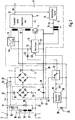
- Figure 1 shows schematically the power supply of a video receiver. This is connected to a local energy network 2 via network inputs 1.
- a rectifier 3 rectifies the input alternating current Iw, which in the example is a bridge rectifier 4 with a storage capacitor 5.
- a switching power supply 6 is connected to this rectifier 3, which transmits the electrical energy stored in the storage capacitor 5 via a switching transistor 7 and a transformer 8 to the secondary side of the switching power supply 6 with the secondary circuit 9.
- the switching transistor 7 is controlled by a pulse generator 10, which is fed by a primary-side power supply part 11 of the switching power supply 6 at an operating voltage connection 12.
- the operating voltages for supplying the video receiver are generated, which are electrically isolated from the local energy network.
- the generated operating voltage Ubs is at an operating voltage output 13.
- a control amplifier 14 is connected to this output, which generates a control signal StS at its control output 15, which is transmitted via a pulse transformer 16 to an input 17 of the pulse generator 10 for disconnection from the mains.
- This control signal StS changes the pulse width of, for example, the line-frequency pulse train of the pulse generator 10 in accordance with the secondary-side operating voltage Ubs.
- the video receiver contains a demagnetizing device 18 which is connected directly to the power lines 20 via the electronic switch 19.
- the electronic switch 19 is a triac with a control path 21, which is connected in parallel with a resistor 23 arranged in a mains line 20 via a limiting resistor 22.
- This low-resistance resistor 23 on the one hand represents the control generator for the control path 21 of the triac 19 and on the other hand limits the peak current through the rectifier diodes in the bridge rectifier 4.
- the demagnetizing device 18 contains the series connection of two demagnetizing coils 26 and 27 for demagnetizing the picture tube of the video receiver, not shown, and a PTC thermistor 24 with a short heating-up time.
- a second PTC thermistor 25 Arranged parallel to the series connection is a second PTC thermistor 25, which is thermally coupled to the first PTC thermistor 24 and has a longer heating-up time.
- the first PTC thermistor 24 is kept at a temperature which sets a high operating resistance in the first PTC thermistor 24, so that almost no current flows through the demagnetizing coils 26 and 27.
- the video receiver contains a receiving decoder 28 with a receiving element 29, for example an infrared receiver for receiving remote control signals 30, which a remote control transmitter, not shown, emits.
- the receiving decoder 28 generates a control signal SpS during the waiting operation at the output 31, which blocks the switching transistor 7 in the switching power supply 6 and is connected on the output side to an electronic switch 32.
- the reception decoder 28 and the electronic switch 32 are fed from a standby power supply 33 which is independent of the switching power supply 6 and which also contains a rectifier bridge 34 and a storage capacitor 35.
- the rectifier bridge 34 is connected, for example, via reactance capacitors 36 and 37 to the mains lines 20 coming from the mains inputs 1.
- the base 38 of the standby power supply 33 is connected to the base 39 of the rectifier 3 for the switching power supply 6.
- a remote control signal is to switch the receiving device to waiting mode.
- the receiving decoder converts the received and recognized command into a corresponding signal SpS.
- the signal SpS reaches the input 40 of the pulse generator 10, which thereby blocks the switching transistor 7 in the switching power supply 6.
- the switching power supply 6 is de-energized and does not generate any operating voltages.
- no alternating current Iw flows via the mains lines 20 and the resistor 23 arranged therein.
- the control voltage for the triac 19 is therefore absent and the triac 19 interrupts the current through the demagnetizing device 18 during the waiting operation.
- the video receiver therefore only consumes as much power as the receiving decoder 28 and the electronic switch 32 require for their operation.
- this power consumption is very small compared to the power consumption that the receiving device requires in the operating state.
- the proportion of the power loss for the standby power supply 33 is insignificant compared to the already low power consumption of the reception decoder 28 and the electronic switch 32, since there is no power loss at the reactance capacitors 36 and 37.
- a remote control signal which switches the video receiver into the operating state, causes the reception decoder 28 to emit a signal SpS.
- the electronic switch 32 which was open during the waiting mode of the receiving device, connects the power supply output 41 of the standby power supply 33 via a switching diode 42 to the operating voltage connection 12 of the pulse generator 10. This begins with the generation of pulses.
- the switched-mode power supply 6 starts up and generates increasing operating voltages in the voltage value.
- the AC current Iw taken from the power network in the power lines 20 generates a control voltage for the electronic switch 19 of the demagnetizing device 18 at the resistor 23.
- This control voltage only opens the triac during part of a current half-wave 43, as the diagram in FIG. 2 shows schematically .
- This causes current pulses 44 to flow through the demagnetizing coils 26 and 27, which slowly heat up the PTC thermistors 24 and 25. The result of this is that the amplitudes of the current pulses slowly decrease and thereby intensely demagnetize the picture tube.
- At the end 46 of the process only a small residual current flows through the demagnetizing coils 26 and 27.
- the power supply part 11 takes over the power supply of the pulse generator 10 and blocks the switching diode 42 for the current from the standby power supply 33.
- the receiving decoder blocks the switching transistor 7 at least until the operating voltages of the switching power supply 6 collapse when a remote control signal for switching the receiving device to the wait mode is received via the pulse generator.
- the receiving decoder effects the supply of the pulse generator 10 from the standby power supply 33 via the electronic switch until the primary-side power supply part 11 of the switching power supply 6 takes over this function.
Applications Claiming Priority (2)
| Application Number | Priority Date | Filing Date | Title |
|---|---|---|---|
| DE4237634 | 1992-11-07 | ||
| DE4237634A DE4237634A1 (de) | 1992-11-07 | 1992-11-07 | Videoempfangsgerät mit einem Schaltnetzteil |
Publications (3)
| Publication Number | Publication Date |
|---|---|
| EP0598267A2 true EP0598267A2 (fr) | 1994-05-25 |
| EP0598267A3 EP0598267A3 (en) | 1994-06-15 |
| EP0598267B1 EP0598267B1 (fr) | 1998-03-04 |
Family
ID=6472338
Family Applications (1)
| Application Number | Title | Priority Date | Filing Date |
|---|---|---|---|
| EP93117638A Expired - Lifetime EP0598267B1 (fr) | 1992-11-07 | 1993-10-30 | Récepteur de télévision muni d'une alimentation à découpage |
Country Status (4)
| Country | Link |
|---|---|
| EP (1) | EP0598267B1 (fr) |
| AT (1) | ATE163826T1 (fr) |
| DE (2) | DE4237634A1 (fr) |
| DK (1) | DK0598267T3 (fr) |
Cited By (4)
| Publication number | Priority date | Publication date | Assignee | Title |
|---|---|---|---|---|
| DE4419581A1 (de) * | 1994-06-03 | 1995-12-07 | Grundig Emv | Vorrichtung zur Stromversorgung eines fernbedienbaren Gerätes der Unterhaltungselektronik im Bereitschaftsbetrieb |
| EP0689351A2 (fr) | 1994-06-23 | 1995-12-27 | NOKIA TECHNOLOGY GmbH | Circuit pour le mode de veille d'un dispositif de télécommande |
| WO1998059499A1 (fr) * | 1997-06-25 | 1998-12-30 | Koninklijke Philips Electronics N.V. | Demagnetisation |
| WO2003090335A1 (fr) * | 2002-04-22 | 2003-10-30 | Thomson Licensing S.A. | Circuit avec correction du facteur de puissance, et appareil correspondant |
Families Citing this family (3)
| Publication number | Priority date | Publication date | Assignee | Title |
|---|---|---|---|---|
| DE19652604A1 (de) * | 1996-04-23 | 1997-10-30 | Thomson Brandt Gmbh | Netzteil für ein Gerät mit Standby-Betrieb |
| ITTO20090214A1 (it) | 2009-03-20 | 2010-09-21 | St Microelectronics Srl | Circuito di alimentazione per l'accensione da remoto di apparecchi elettrici |
| DE102013009897B4 (de) * | 2013-06-13 | 2022-05-25 | Diehl Aerospace Gmbh | Spannungsversorgung für eine elektronische Baugruppe und eine Steuerungseinrichtung sowie Diodenbeleuchtungsvorrichtung mit der Spannungsversorgung und Betriebsverfahren |
Citations (3)
| Publication number | Priority date | Publication date | Assignee | Title |
|---|---|---|---|---|
| EP0167737A1 (fr) * | 1984-07-13 | 1986-01-15 | Deutsche Thomson-Brandt GmbH | Conception de circuit pour un appareil de télévision à fonctionnement en mode de veille |
| EP0436515A2 (fr) * | 1990-01-05 | 1991-07-10 | RCA Thomson Licensing Corporation | Appareil d'alimentation de puissance commandé à distance |
| EP0477399A1 (fr) * | 1990-09-25 | 1992-04-01 | Siemens Aktiengesellschaft | Dispositif pour démagnétiser un tube d'image |
Family Cites Families (5)
| Publication number | Priority date | Publication date | Assignee | Title |
|---|---|---|---|---|
| US4441052A (en) * | 1982-11-26 | 1984-04-03 | Rca Corporation | Degaussing circuit for television receiver having switched mode power supply |
| DE3418076C2 (de) * | 1984-05-16 | 1986-06-26 | Loewe Opta Gmbh, 8640 Kronach | Schaltungsanordnung zur automatischen Entmagnetisierung der Bildröhre in einem Farbfernsehempfänger |
| DE3421386A1 (de) * | 1984-06-08 | 1985-12-12 | A. Nattermann & Cie GmbH, 5000 Köln | Neue n-pyrazolyl-1,2-benzothiazin-3-carboxamide und diese enthaltende pharmazeutische praeparate |
| US4737853A (en) * | 1987-04-30 | 1988-04-12 | Rca Corporation | Suppression circuit for video |
| EP0339411B1 (fr) * | 1988-04-26 | 1992-08-12 | Hoechst Aktiengesellschaft | Procédé pour la préparation de quinoxalones |
-
1992
- 1992-11-07 DE DE4237634A patent/DE4237634A1/de not_active Withdrawn
-
1993
- 1993-10-30 AT AT93117638T patent/ATE163826T1/de active
- 1993-10-30 DK DK93117638T patent/DK0598267T3/da active
- 1993-10-30 EP EP93117638A patent/EP0598267B1/fr not_active Expired - Lifetime
- 1993-10-30 DE DE59308205T patent/DE59308205D1/de not_active Expired - Lifetime
Patent Citations (3)
| Publication number | Priority date | Publication date | Assignee | Title |
|---|---|---|---|---|
| EP0167737A1 (fr) * | 1984-07-13 | 1986-01-15 | Deutsche Thomson-Brandt GmbH | Conception de circuit pour un appareil de télévision à fonctionnement en mode de veille |
| EP0436515A2 (fr) * | 1990-01-05 | 1991-07-10 | RCA Thomson Licensing Corporation | Appareil d'alimentation de puissance commandé à distance |
| EP0477399A1 (fr) * | 1990-09-25 | 1992-04-01 | Siemens Aktiengesellschaft | Dispositif pour démagnétiser un tube d'image |
Non-Patent Citations (1)
| Title |
|---|
| ELECTOR ELECTRONICS Bd. 13, Nr. 149 , Oktober 1987 , LONDON (GB) Seiten 49 - 53 ANONYMOUS 'SWITCH-MODE POWER SUPPLIES' * |
Cited By (9)
| Publication number | Priority date | Publication date | Assignee | Title |
|---|---|---|---|---|
| DE4419581A1 (de) * | 1994-06-03 | 1995-12-07 | Grundig Emv | Vorrichtung zur Stromversorgung eines fernbedienbaren Gerätes der Unterhaltungselektronik im Bereitschaftsbetrieb |
| EP0689351A2 (fr) | 1994-06-23 | 1995-12-27 | NOKIA TECHNOLOGY GmbH | Circuit pour le mode de veille d'un dispositif de télécommande |
| DE4421869A1 (de) * | 1994-06-23 | 1996-01-04 | Nokia Deutschland Gmbh | Schaltungsanordnung für den Wartebetrieb eines fernbedienbaren Gerätes |
| EP0689351A3 (fr) * | 1994-06-23 | 1996-02-07 | Nokia Technology Gmbh | Circuit pour le mode de veille d'un dispositif de télécommande |
| WO1998059499A1 (fr) * | 1997-06-25 | 1998-12-30 | Koninklijke Philips Electronics N.V. | Demagnetisation |
| US5940261A (en) * | 1997-06-25 | 1999-08-17 | U.S. Philips Corporation | Circuit and method independent of frequency and voltage deviations of supply voltage, and display apparatus incorporating same circuit |
| WO2003090335A1 (fr) * | 2002-04-22 | 2003-10-30 | Thomson Licensing S.A. | Circuit avec correction du facteur de puissance, et appareil correspondant |
| US7120003B2 (en) | 2002-04-22 | 2006-10-10 | Thomson Licensing | Circuit arrangement with power factor correction, as well as a corresponding appliance |
| CN100392962C (zh) * | 2002-04-22 | 2008-06-04 | 汤姆森特许公司 | 具有功率因数校正的电路装置及其相应的设备 |
Also Published As
| Publication number | Publication date |
|---|---|
| DE59308205D1 (de) | 1998-04-09 |
| ATE163826T1 (de) | 1998-03-15 |
| DE4237634A1 (de) | 1994-05-11 |
| EP0598267A3 (en) | 1994-06-15 |
| DK0598267T3 (da) | 1998-09-28 |
| EP0598267B1 (fr) | 1998-03-04 |
Similar Documents
| Publication | Publication Date | Title |
|---|---|---|
| DE2345073B2 (de) | Netzgerät | |
| DE3343031C2 (de) | Entmagnetisierungsschaltung für einen Fernsehempfänger mit Schaltnetzteil | |
| DE2658903A1 (de) | Schalt-spannungsregler | |
| EP0135119B1 (fr) | Convertisseur à récupération | |
| DE3118816C2 (de) | Entmagnetisierungsschaltung für einen Farbfernseher | |
| DE2620191A1 (de) | Schaltnetzteil fuer die versorgung eines fernsehgeraetes | |
| EP0598267B1 (fr) | Récepteur de télévision muni d'une alimentation à découpage | |
| DE3328181C1 (de) | Bereitschaftsbetrieb bei einer mit einem Schaltnetzteil kombinierten Horizonttalendstufenschaltung | |
| DE2624965C2 (de) | Kurzschlußfestes Schaltnetzteil für einen Fernsehempfänger | |
| DE19545659A1 (de) | Schaltnetzteil für Normalbetrieb und Bereitschaftsbetrieb | |
| EP0064610B1 (fr) | Outil de soudage chauffé électriquement | |
| DE3044917C2 (de) | Entmagnetisierungsschaltung für einen Farbfernsehempfänger | |
| WO1986005345A1 (fr) | Concept alimentation electrique-balayage pour postes de television | |
| EP0230930B1 (fr) | Alimentation à découpage pour appareil à commande à distance | |
| DE3302756C2 (de) | Fernsehwiedergabeanordnung | |
| DE2525122C3 (de) | Speiseschaltung für eine Thyristor-Horzontalablenkstufe eines Fernsehempfängers | |
| DE3030143C2 (de) | Schaltnetzteil | |
| EP0308617B1 (fr) | Téléviseur avec un circuit de commande en mode veille | |
| DE3249202T1 (de) | Schutzschaltung fuer die stromversorgung eines fernsteuerbaren fernsehempfaengers | |
| EP0695023A1 (fr) | Alimentation à découpage avec circuit amortisseur | |
| EP0232915B1 (fr) | Disposition de circuit d'une source de tension continue se basant sur la résonance | |
| DD274308A1 (de) | Sperrwandler-schaltnetzteil mit bereitschaftsbetrieb | |
| EP0223171A2 (fr) | Bloc d'alimentation à découpage | |
| DE19649403A1 (de) | Schaltnetzteil mit Regelung der Ausgangsspannung | |
| EP0166902B1 (fr) | Etage d'attaque à consommation de puissance réduite pour récepteur de télévision en mode d'attente |
Legal Events
| Date | Code | Title | Description |
|---|---|---|---|
| PUAI | Public reference made under article 153(3) epc to a published international application that has entered the european phase |
Free format text: ORIGINAL CODE: 0009012 |
|
| PUAL | Search report despatched |
Free format text: ORIGINAL CODE: 0009013 |
|
| AK | Designated contracting states |
Kind code of ref document: A2 Designated state(s): AT BE DE DK FR GB IT NL |
|
| AK | Designated contracting states |
Kind code of ref document: A3 Designated state(s): AT BE DE DK FR GB IT NL |
|
| 17P | Request for examination filed |
Effective date: 19941118 |
|
| 17Q | First examination report despatched |
Effective date: 19961211 |
|
| GRAG | Despatch of communication of intention to grant |
Free format text: ORIGINAL CODE: EPIDOS AGRA |
|
| GRAG | Despatch of communication of intention to grant |
Free format text: ORIGINAL CODE: EPIDOS AGRA |
|
| GRAH | Despatch of communication of intention to grant a patent |
Free format text: ORIGINAL CODE: EPIDOS IGRA |
|
| GRAH | Despatch of communication of intention to grant a patent |
Free format text: ORIGINAL CODE: EPIDOS IGRA |
|
| GRAA | (expected) grant |
Free format text: ORIGINAL CODE: 0009210 |
|
| AK | Designated contracting states |
Kind code of ref document: B1 Designated state(s): AT BE DE DK FR GB IT NL |
|
| REF | Corresponds to: |
Ref document number: 163826 Country of ref document: AT Date of ref document: 19980315 Kind code of ref document: T |
|
| ITF | It: translation for a ep patent filed |
Owner name: JACOBACCI & PERANI S.P.A. |
|
| GBT | Gb: translation of ep patent filed (gb section 77(6)(a)/1977) |
Effective date: 19980306 |
|
| REF | Corresponds to: |
Ref document number: 59308205 Country of ref document: DE Date of ref document: 19980409 |
|
| ET | Fr: translation filed | ||
| REG | Reference to a national code |
Ref country code: DK Ref legal event code: T3 |
|
| PLBE | No opposition filed within time limit |
Free format text: ORIGINAL CODE: 0009261 |
|
| STAA | Information on the status of an ep patent application or granted ep patent |
Free format text: STATUS: NO OPPOSITION FILED WITHIN TIME LIMIT |
|
| 26N | No opposition filed | ||
| REG | Reference to a national code |
Ref country code: GB Ref legal event code: IF02 |
|
| REG | Reference to a national code |
Ref country code: GB Ref legal event code: 732E |
|
| NLS | Nl: assignments of ep-patents |
Owner name: SOCIETA ITALIANA PER LO SVILUPPO DELL'ELETTRONICA |
|
| REG | Reference to a national code |
Ref country code: FR Ref legal event code: TP |
|
| PGFP | Annual fee paid to national office [announced via postgrant information from national office to epo] |
Ref country code: DK Payment date: 20121024 Year of fee payment: 20 |
|
| PGFP | Annual fee paid to national office [announced via postgrant information from national office to epo] |
Ref country code: FR Payment date: 20121205 Year of fee payment: 20 Ref country code: BE Payment date: 20121026 Year of fee payment: 20 Ref country code: DE Payment date: 20121211 Year of fee payment: 20 |
|
| PGFP | Annual fee paid to national office [announced via postgrant information from national office to epo] |
Ref country code: GB Payment date: 20121024 Year of fee payment: 20 Ref country code: IT Payment date: 20121023 Year of fee payment: 20 |
|
| PGFP | Annual fee paid to national office [announced via postgrant information from national office to epo] |
Ref country code: AT Payment date: 20121022 Year of fee payment: 20 Ref country code: NL Payment date: 20121018 Year of fee payment: 20 |
|
| BE20 | Be: patent expired |
Owner name: *SOCIETA ITALIANA PER LO SVILUPPO DELL'ELETTRONICA Effective date: 20131030 |
|
| REG | Reference to a national code |
Ref country code: DE Ref legal event code: R071 Ref document number: 59308205 Country of ref document: DE |
|
| REG | Reference to a national code |
Ref country code: DK Ref legal event code: EUP Effective date: 20131030 |
|
| REG | Reference to a national code |
Ref country code: NL Ref legal event code: V4 Effective date: 20131030 |
|
| REG | Reference to a national code |
Ref country code: GB Ref legal event code: PE20 Expiry date: 20131029 |
|
| REG | Reference to a national code |
Ref country code: AT Ref legal event code: MK07 Ref document number: 163826 Country of ref document: AT Kind code of ref document: T Effective date: 20131030 |
|
| PG25 | Lapsed in a contracting state [announced via postgrant information from national office to epo] |
Ref country code: DE Free format text: LAPSE BECAUSE OF EXPIRATION OF PROTECTION Effective date: 20131031 Ref country code: GB Free format text: LAPSE BECAUSE OF EXPIRATION OF PROTECTION Effective date: 20131029 |