EP0598267A2 - Television receiver with a switching power supply - Google Patents
Television receiver with a switching power supply Download PDFInfo
- Publication number
- EP0598267A2 EP0598267A2 EP93117638A EP93117638A EP0598267A2 EP 0598267 A2 EP0598267 A2 EP 0598267A2 EP 93117638 A EP93117638 A EP 93117638A EP 93117638 A EP93117638 A EP 93117638A EP 0598267 A2 EP0598267 A2 EP 0598267A2
- Authority
- EP
- European Patent Office
- Prior art keywords
- power supply
- video receiver
- switching power
- switched
- receiving
- Prior art date
- Legal status (The legal status is an assumption and is not a legal conclusion. Google has not performed a legal analysis and makes no representation as to the accuracy of the status listed.)
- Granted
Links
Images

Classifications
-
- H—ELECTRICITY
- H04—ELECTRIC COMMUNICATION TECHNIQUE
- H04N—PICTORIAL COMMUNICATION, e.g. TELEVISION
- H04N5/00—Details of television systems
- H04N5/63—Generation or supply of power specially adapted for television receivers
-
- H—ELECTRICITY
- H02—GENERATION; CONVERSION OR DISTRIBUTION OF ELECTRIC POWER
- H02M—APPARATUS FOR CONVERSION BETWEEN AC AND AC, BETWEEN AC AND DC, OR BETWEEN DC AND DC, AND FOR USE WITH MAINS OR SIMILAR POWER SUPPLY SYSTEMS; CONVERSION OF DC OR AC INPUT POWER INTO SURGE OUTPUT POWER; CONTROL OR REGULATION THEREOF
- H02M7/00—Conversion of ac power input into dc power output; Conversion of dc power input into ac power output
- H02M7/02—Conversion of ac power input into dc power output without possibility of reversal
- H02M7/04—Conversion of ac power input into dc power output without possibility of reversal by static converters
- H02M7/05—Capacitor coupled rectifiers
Definitions
- the invention relates to a video receiver with a switched-mode power supply connected to the power supply inputs of the receiver according to the preamble of claim 1.
- a video receiver is known from German patent DE-C2 33 43 031, in which the switched-mode power supply is switched off during waiting operation.
- the remote control receiver of the device therefore receives its operating voltage from an additional standby power supply that is independent of the switching power supply of the device and contains a network transformer that separates the remote control receiver from the energy network.
- the remote control receiver which converts received remote control signals into control commands, delivers the required operating current from the standby power supply and a control signal when a signal for switching on the video receiver arrives at a controller control circuit.
- This regulator control circuit activates the switching power supply with a pulse-shaped control signal. Since the standby power supply is constantly under operating voltage during the waiting operation, a considerable power requirement arises. It is desirable to reduce this.
- the power requirement in the operating state of the video receiver is additionally increased in that the excitation winding of a relay for switching on the demagnetizing device is operated in parallel with the primary winding of the transformer by the switching power supply via an ohmic series resistor.
- the demagnetization circuit can be switched on via a bipolar electronic switch (triac). Both the electronic switch of the demagnetizing circuit and the switching transistor for the line transformer circuit are switched on by line-frequency control pulses which are supplied via a pulse transformer.
- This circuit also has the disadvantage that it requires a relatively large amount of energy, since the horizontal oscillator and the remote control receiver are constantly connected to the decoder in waiting mode via means for reducing the operating voltage, which are not detailed, with the rectified high mains voltage.
- the invention has for its object to significantly reduce the power consumption of a video receiver in waiting mode. This object is achieved according to the invention by the features specified in the text of the characterizing part of claim 1 in an advantageous manner.
- a video receiver in waiting mode only absorbs a power loss of the order of 1/10 watt.
- the power reduction is achieved, on the one hand, by arranging a receiver decoder for recognizing the remote control signals for switching between the operating state and waiting mode of the video receiver on the network-connected primary side of the switched-mode power supply and supplying operating current from a transformerless power supply that is independent of the switched-mode power supply and with low active losses.
- the switched-mode power supply is switched off completely in a known manner during the waiting operation of the video receiver.
- the switching power supply for operating the video receiver with the remote control is switched on in that the pulse generator for the switching transistor of the switching power supply receives the first operating current from the standby power supply until the switching power supply takes over the further power supply for the pulse generator.
- the other measure is that the demagnetizing device for the picture tube of the video receiver, which is de-energized in a known manner by an electronic switch during waiting operation, is controlled according to the invention by the input current that the receiving device obtains from the energy network.
- the demagnetizing device is thus put into operation exclusively via the operating current of the switching power supply.
- the electronic switch of the demagnetizing device is only switched on during part of a half-wave each time, so that the picture tube is demagnetized each time after switching from the waiting mode to the operating state by decreasing current pulses.
- the standby power supply which is independent of the switching power supply and is a rectifier circuit with an output storage capacitor, is capacitively connected to the network inputs of the video receiver in order to reduce the operating voltage for the remote control decoder. This causes a power loss that is negligible compared to the power loss of the remote control decoder to be supplied.
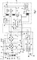
- Figure 1 shows schematically the power supply of a video receiver. This is connected to a local energy network 2 via network inputs 1.
- a rectifier 3 rectifies the input alternating current Iw, which in the example is a bridge rectifier 4 with a storage capacitor 5.
- a switching power supply 6 is connected to this rectifier 3, which transmits the electrical energy stored in the storage capacitor 5 via a switching transistor 7 and a transformer 8 to the secondary side of the switching power supply 6 with the secondary circuit 9.
- the switching transistor 7 is controlled by a pulse generator 10, which is fed by a primary-side power supply part 11 of the switching power supply 6 at an operating voltage connection 12.
- the operating voltages for supplying the video receiver are generated, which are electrically isolated from the local energy network.
- the generated operating voltage Ubs is at an operating voltage output 13.
- a control amplifier 14 is connected to this output, which generates a control signal StS at its control output 15, which is transmitted via a pulse transformer 16 to an input 17 of the pulse generator 10 for disconnection from the mains.
- This control signal StS changes the pulse width of, for example, the line-frequency pulse train of the pulse generator 10 in accordance with the secondary-side operating voltage Ubs.
- the video receiver contains a demagnetizing device 18 which is connected directly to the power lines 20 via the electronic switch 19.
- the electronic switch 19 is a triac with a control path 21, which is connected in parallel with a resistor 23 arranged in a mains line 20 via a limiting resistor 22.
- This low-resistance resistor 23 on the one hand represents the control generator for the control path 21 of the triac 19 and on the other hand limits the peak current through the rectifier diodes in the bridge rectifier 4.
- the demagnetizing device 18 contains the series connection of two demagnetizing coils 26 and 27 for demagnetizing the picture tube of the video receiver, not shown, and a PTC thermistor 24 with a short heating-up time.
- a second PTC thermistor 25 Arranged parallel to the series connection is a second PTC thermistor 25, which is thermally coupled to the first PTC thermistor 24 and has a longer heating-up time.
- the first PTC thermistor 24 is kept at a temperature which sets a high operating resistance in the first PTC thermistor 24, so that almost no current flows through the demagnetizing coils 26 and 27.
- the video receiver contains a receiving decoder 28 with a receiving element 29, for example an infrared receiver for receiving remote control signals 30, which a remote control transmitter, not shown, emits.
- the receiving decoder 28 generates a control signal SpS during the waiting operation at the output 31, which blocks the switching transistor 7 in the switching power supply 6 and is connected on the output side to an electronic switch 32.
- the reception decoder 28 and the electronic switch 32 are fed from a standby power supply 33 which is independent of the switching power supply 6 and which also contains a rectifier bridge 34 and a storage capacitor 35.
- the rectifier bridge 34 is connected, for example, via reactance capacitors 36 and 37 to the mains lines 20 coming from the mains inputs 1.
- the base 38 of the standby power supply 33 is connected to the base 39 of the rectifier 3 for the switching power supply 6.
- a remote control signal is to switch the receiving device to waiting mode.
- the receiving decoder converts the received and recognized command into a corresponding signal SpS.
- the signal SpS reaches the input 40 of the pulse generator 10, which thereby blocks the switching transistor 7 in the switching power supply 6.
- the switching power supply 6 is de-energized and does not generate any operating voltages.
- no alternating current Iw flows via the mains lines 20 and the resistor 23 arranged therein.
- the control voltage for the triac 19 is therefore absent and the triac 19 interrupts the current through the demagnetizing device 18 during the waiting operation.
- the video receiver therefore only consumes as much power as the receiving decoder 28 and the electronic switch 32 require for their operation.
- this power consumption is very small compared to the power consumption that the receiving device requires in the operating state.
- the proportion of the power loss for the standby power supply 33 is insignificant compared to the already low power consumption of the reception decoder 28 and the electronic switch 32, since there is no power loss at the reactance capacitors 36 and 37.
- a remote control signal which switches the video receiver into the operating state, causes the reception decoder 28 to emit a signal SpS.
- the electronic switch 32 which was open during the waiting mode of the receiving device, connects the power supply output 41 of the standby power supply 33 via a switching diode 42 to the operating voltage connection 12 of the pulse generator 10. This begins with the generation of pulses.
- the switched-mode power supply 6 starts up and generates increasing operating voltages in the voltage value.
- the AC current Iw taken from the power network in the power lines 20 generates a control voltage for the electronic switch 19 of the demagnetizing device 18 at the resistor 23.
- This control voltage only opens the triac during part of a current half-wave 43, as the diagram in FIG. 2 shows schematically .
- This causes current pulses 44 to flow through the demagnetizing coils 26 and 27, which slowly heat up the PTC thermistors 24 and 25. The result of this is that the amplitudes of the current pulses slowly decrease and thereby intensely demagnetize the picture tube.
- At the end 46 of the process only a small residual current flows through the demagnetizing coils 26 and 27.
- the power supply part 11 takes over the power supply of the pulse generator 10 and blocks the switching diode 42 for the current from the standby power supply 33.
- the receiving decoder blocks the switching transistor 7 at least until the operating voltages of the switching power supply 6 collapse when a remote control signal for switching the receiving device to the wait mode is received via the pulse generator.
- the receiving decoder effects the supply of the pulse generator 10 from the standby power supply 33 via the electronic switch until the primary-side power supply part 11 of the switching power supply 6 takes over this function.
Abstract
Description
Die Erfindung betrifft einen Videoempfänger mit einem an die Stromversorgungseingänge des Empfängers angeschlossenen Schaltnetzteil gemäß dem Oberbegriff des Anspruches 1.The invention relates to a video receiver with a switched-mode power supply connected to the power supply inputs of the receiver according to the preamble of
Es ist bekannt, Fernsehempfänger und ähnliche Geräte mit einem Schaltnetzteil, das im allgemeinen mit der Zeilenfrequenz getaktet wird, auszustatten und mittels einer Fernbedienung in einen leistungsarmen Wartebetrieb (Stand-by) zu schalten, anstelle sie vollständig abzuschalten. Dadurch ist es möglich, das Gerät wieder bequem mittels eines Fernbediengebers in den Betriebszustand zu schalten.It is known to equip television receivers and similar devices with a switching power supply, which is generally clocked at the line frequency, and to switch them into a low-power waiting mode (stand-by) by means of a remote control, instead of switching them off completely. This makes it possible to switch the device back into the operating state conveniently using a remote control.
Darüber hinaus ist aus der deutschen Patentschrift DE-C2 33 43 031 ein Videoempfänger bekannt, bei dem das Schaltnetzteil während des Wartebetriebes stromlos geschaltet ist. Der Fernbedienempfänger des Gerätes erhält deshalb seine Betriebsspannung von einem zusätzlichen Bereitschaftsnetzteil, das vom Schaltnetzteil des Gerätes unabhängig ist und einen Netztransformator enthält, der den Fernbedienempfänger vom Energienetz trennt.
Der Fernbedienempfänger, der empfangene Fernbediensignale in Steuerbefehle umsetzt, liefert beim Eintreffen eines Signals zum Einschalten des Videoempfängers an eine Reglersteuerschaltung den erforderlichen Betriebsstrom aus dem Bereitschaftsnetzteil und ein Steuersignal. Diese Reglersteuerschaltung aktiviert das Schaltnetzteil mit einem impulsförmigen Steuersignals.
Da das Bereitschaftsnetzteil während des Wartebetriebes ständig unter Betriebsspannung steht, tritt ein beachtlicher Leistungsbedarf auf. Es ist wünschenswert, diesen zu reduzieren.In addition, a video receiver is known from German patent DE-C2 33 43 031, in which the switched-mode power supply is switched off during waiting operation. The remote control receiver of the device therefore receives its operating voltage from an additional standby power supply that is independent of the switching power supply of the device and contains a network transformer that separates the remote control receiver from the energy network.
The remote control receiver, which converts received remote control signals into control commands, delivers the required operating current from the standby power supply and a control signal when a signal for switching on the video receiver arrives at a controller control circuit. This regulator control circuit activates the switching power supply with a pulse-shaped control signal.
Since the standby power supply is constantly under operating voltage during the waiting operation, a considerable power requirement arises. It is desirable to reduce this.
Darüber hinaus wird bei dieser bekannten Lösung der Leistungsbedarf im Betriebszustand des Videoempfängers noch dadurch zusätzlich erhöht, daß parallel zur Primärwicklung des Transformators vom Schaltnetzteil über einen ohmschen Vorwiderstand die Erregerwicklung eines Relais zum Anschalten der Entmagnetsiervorrichtung betrieben wird.In addition, in this known solution, the power requirement in the operating state of the video receiver is additionally increased in that the excitation winding of a relay for switching on the demagnetizing device is operated in parallel with the primary winding of the transformer by the switching power supply via an ohmic series resistor.
Desweiteren ist aus der Druckschrift DE-C2 34 18 076 ein fernbedienbares Fernsehgerät ohne einem Netztransformator im Bereitschaftsnetzteil bekannt. Bei diesem Gerät werden die Betriebsspannung für den Fernbedienempfänger vom Netzteilgleichrichter, welcher mit dem Leistungsnetz galvanisch verbunden ist, und die Betriebsspannungen für die übrigen Teile der Schaltung des Videoempfängers vom Zeilentransformator der Horizontalablenkschaltung abgegriffen.Furthermore, from the document DE-C2 34 18 076 a remote-controlled television set without a power transformer in the standby power supply is known. In this device, the operating voltage for the remote control receiver from the power supply rectifier, which is galvanically connected to the power network, and the operating voltages for the other parts of the circuit of the video receiver are tapped from the line transformer of the horizontal deflection circuit.
Die Entmagnetisierschaltung ist über einen bipolaren elektronischen Schalter (Triac) anschaltbar. Sowohl der elektronische Schalter der Entmagnetisierschaltung als auch der Schalttransistor für Zeilentransformatorschaltung werden von zeilenfrequenten Steuerimpulsen, die über einen Impulsübertrager zugeführt werden, leitend geschaltet.The demagnetization circuit can be switched on via a bipolar electronic switch (triac). Both the electronic switch of the demagnetizing circuit and the switching transistor for the line transformer circuit are switched on by line-frequency control pulses which are supplied via a pulse transformer.
Auch diese Schaltung hat den Nachteil, daß sie relativ viel Energie benötigt, da der Horizontaloszillator und der Fernsteuerempfänger mit dem Decoder im Wartebetrieb ständig über nicht näher ausgeführte Mittel zum Reduzieren der Betriebsspannung mit der gleichgerichteten hohen Netzspannung verbunden sind.This circuit also has the disadvantage that it requires a relatively large amount of energy, since the horizontal oscillator and the remote control receiver are constantly connected to the decoder in waiting mode via means for reducing the operating voltage, which are not detailed, with the rectified high mains voltage.
Durch diese Schaltung ergibt sich somit auch keine Reduzierung der Leistung im Wartebetrieb, sondern lediglich eine Einsparung von teuren Bauelementen.With this circuit, there is therefore no reduction in the power in the waiting mode, but only a saving of expensive components.
Der Erfindung liegt die Aufgabe zugrunde, die Leistungsaufnahme eines Videoempfängers im Wartebetrieb wesentlich zu reduzieren.
Diese Aufgabe wird nach der Erfindung durch die im Text des kennzeichnenden Teiles des Anspruches 1 angegebenen Merkmale in vorteilhafter Weise gelöst.The invention has for its object to significantly reduce the power consumption of a video receiver in waiting mode.
This object is achieved according to the invention by the features specified in the text of the characterizing part of
Durch die erfindungsgemäßen Maßnahmen nimmt ein Videoempfänger im Wartebetrieb nur noch eine Verlustleistung in der Größenordnung von 1/10 Watt auf. Die Leistungsreduktion wird zum einen dadurch erreicht, daß ein Empfängerdekoder zum Erkennen der Fernbediensignale zum Umschalten zwischen Betriebszustand und Wartebetrieb des Videoempfängers auf der netzverbundenen Primärseite des Schaltnetzteiles angeordnet ist und aus einem vom Schaltnetzteil unabhängigen transformatorlosen Netzteil mit geringen Wirkverlusten mit Betriebsstrom versorgt wird. Das Schaltnetzteil wird in bekannter Weise, während des Wartebetriebes des Videoempfängers vollständig stromlos geschaltet. Das Einschalten des Schaltnetzteiles zum Betrieb des Videoempfängers mit der Fernbedienung erfolgt dadurch, daß der Impulsgenerator für den Schalttransistor des Schaltnetzteiles aus dem Bereitschaftsnetzteil den ersten Betriebsstrom erhält, bis das Schaltnetzteiles die weitere Stromversorgung für den Impulsgenerator übernimmt.As a result of the measures according to the invention, a video receiver in waiting mode only absorbs a power loss of the order of 1/10 watt. The power reduction is achieved, on the one hand, by arranging a receiver decoder for recognizing the remote control signals for switching between the operating state and waiting mode of the video receiver on the network-connected primary side of the switched-mode power supply and supplying operating current from a transformerless power supply that is independent of the switched-mode power supply and with low active losses. The switched-mode power supply is switched off completely in a known manner during the waiting operation of the video receiver. The switching power supply for operating the video receiver with the remote control is switched on in that the pulse generator for the switching transistor of the switching power supply receives the first operating current from the standby power supply until the switching power supply takes over the further power supply for the pulse generator.
Die andere Maßnahme ist die, daß die Entmagnetisiereinrichtung für die Bildröhre des Videoempfängers, die während des Wartebetriebes in bekannter Weise durch einen elektronischen Schalter stromlos geschaltet ist, erfindungsgemäß vom Eingangsstrom, den das Empfangsgerät aus dem Energienetz bezieht, gesteuert wird. Die Entmagnetisiereinrichtung wird somit ausschließlich über den Betriebsstrom des Schaltnetzteiles in Betrieb gesetzt.The other measure is that the demagnetizing device for the picture tube of the video receiver, which is de-energized in a known manner by an electronic switch during waiting operation, is controlled according to the invention by the input current that the receiving device obtains from the energy network. The demagnetizing device is thus put into operation exclusively via the operating current of the switching power supply.
Der elektronische Schalter der Entmagnetisiereinrichtung wird jedesmal nur während eines Teiles einer Halbwelle eingeschaltet, so daß die Bildröhre jedesmal nach dem Umschalten vom Wartebetrieb in den Betriebszustand durch abnehmende Stromimpulse entmagnetisiert wird.The electronic switch of the demagnetizing device is only switched on during part of a half-wave each time, so that the picture tube is demagnetized each time after switching from the waiting mode to the operating state by decreasing current pulses.
Die Unteransprüche kennzeichnen vorteilhafte Ausgestaltungen der Erfindung.The subclaims characterize advantageous embodiments of the invention.
Es ist vorteilhaft, daß das vom Schaltnetzteil unabhängige Bereitschaftsnetzteil, welche eine Gleichrichterschaltung mit einem ausgangsseitigen Speicherkondensator ist, zum Reduzieren der Betriebsspannung für den Fernbediendecoder kapazitiv an die Netzeingänge des Videoempfängers angeschlossen ist. Dieses bewirkt eine Verlustleistung, die gegenüber der Verlustleistung des zu versorgenden Fernbediendecoders vernachlässigbar ist.It is advantageous that the standby power supply, which is independent of the switching power supply and is a rectifier circuit with an output storage capacitor, is capacitively connected to the network inputs of the video receiver in order to reduce the operating voltage for the remote control decoder. This causes a power loss that is negligible compared to the power loss of the remote control decoder to be supplied.
Die Erfindung wird nachfolgend anhand vorteilhafter Ausführungsbeispiele näher erläutert.The invention is explained in more detail below on the basis of advantageous exemplary embodiments.
Die Zeichnungen zeigen:
Figur 1- ein Blockschaltbild der Stromversorgungen eines Videoempfängers mit Entmagnetisiereinrichtung,
Figur 2- ein Diagramm zum Verlauf des Stromes in der Entmagnetisiereinrichtung.
- Figure 1
- 2 shows a block diagram of the power supplies of a video receiver with demagnetizing device,
- Figure 2
- a diagram of the course of the current in the demagnetizer.
Die Figur 1 zeigt schematisch die Stromversorgung eines Videoempfängers. Dieser ist über Netzeingänge 1 an ein örtliches Energienetz 2 angeschlossen. Ein Gleichrichter 3 richtet den Eingangswechselstrom Iw gleich, der im Beispiel ein Brückengleichrichter 4 mit einem Speicherkondensator 5 ist.Figure 1 shows schematically the power supply of a video receiver. This is connected to a
An diesem Gleichrichter 3 ist ein Schaltnetzteil 6 angeschlossen, das die im Speicherkondensator 5 gespeicherte elektrische Energie über einen Schalttransistor 7 und einen Transformator 8 auf die Sekundärseite des Schaltnetzteiles 6 mit der Sekundärschaltung 9 überträgt. Der Schalttransistor 7 wird von einem Impulsgenerator 10 gesteuert, der von einem primärseitigen Stromversorgungsteil 11 des Schaltnetzteiles 6 an einem Betriebsspannungsanschluß 12 gespeist wird.A switching power supply 6 is connected to this rectifier 3, which transmits the electrical energy stored in the storage capacitor 5 via a switching transistor 7 and a transformer 8 to the secondary side of the switching power supply 6 with the
In der Sekundärschaltung 9 des Schaltnetzteiles 6 werden die Betriebsspannungen zum Versorgen des Videoempfängers erzeugt, die galvanisch vom örtlichen Energienetz getrennt sind. An einem Betriebsspannungsausgang 13 liegt die erzeugte Betriebsspannung Ubs. An diesen Ausgang ist ein Regelerverstärker 14 angeschlossen, der an seinem Stellausgang 15 ein Stellsignal StS erzeugt, das über einen Impulsübertrager 16 zur Netztrennung an einen Eingang 17 des Impulsgenerators 10 übertragen wird. Dieses Stellsignal StS verändert die Impulsbreite der zum Beispiel zeilenfrequenten Impulsfolge des Impulsgenerators 10 entsprechend der sekundärseitigen Betriebsspannung Ubs.In the
Außerdem enthält der Videoempfänger eine Entmagnetisiereinrichtung 18, die über den elektronischen Schalter 19 unmittelbar an die Netzleitungen 20 angeschlossen ist. Im Beispiel ist der elektronische Schalter 19 ein Triac mit einer Steuerstrecke 21, die über einen Begrenzungswiderstand 22 parallel zu einem in einer Netzleitung 20 angeordneten Widerstand 23 geschaltet ist. Dieser niederohmige Widerstand 23 stellt einerseits den Steuergenerator für die Steuerstrecke 21 des Triac 19 dar und begrenzt andererseits den Spitzenstrom durch die Gleichrichterdioden im Brückengleichrichter 4.In addition, the video receiver contains a
Die Entmagnetisiereinrichtung 18 enthält die Serienschaltung zweier Entmagnetisierspulen 26 und 27 zum Entmagnetisieren der nicht näher dargestellten Bildröhre des Videoempfängers und einen Kaltleiter 24 mit kurzer Aufheizzeit. Parallel zur Reihenschaltung ist ein zweiter Kaltleiter 25 angeordnet, der thermisch mit dem ersten Kaltleiter 24 gekoppelt ist und eine längere Aufheizzeit aufweist. Dadurch wird nach der Aufheizzeit des zweiten Kaltleiters 25 der erste Kaltleiter 24 auf einer Temperatur gehalten, die einen hohen Betriebswiderstand im ersten Kaltleiter 24 einstellt, so daß nahezu kein Strom mehr durch die Entmagnetisierspulen 26 und 27 fließt.The demagnetizing
Ferner enthält der Videoempfänger einen Empfangsdecoder 28 mit einem Empfangselement 29, beispielsweise einen Infrarotempfänger zum Empfang von Fernbediensignalen 30, die ein nicht näher dargestellter Fernbediengeber aussendet. Der Empfangsdecoder 28 erzeugt während des Wartebetriebes am Ausgang 31 ein Steuersignal SpS, das den Schalttransistors 7 im Schaltnetzteil 6 sperrt und ausgangsseitig mit einem elektronischen Schalter 32 verbunden ist. Der Empfangsdecoder 28 und der elektronische Schalter 32 werden aus einem vom Schaltnetzteil 6 unabhängigen Bereitschaftsnetzteil 33 gespeist, das ebenfalls eine Gleichrichterbrücke 34 und einen Speicherkondensator 35 enthält. Die Gleichrichterbrücke 34 ist zum Beispiel über Reaktanzkondensatoren 36 und 37 an die von den Netzeingängen 1 kommenden Netzleitungen 20 angeschlossen. Der Fußpunkt 38 des Bereitschaftsnetzteils 33 ist mit dem Fußpunkt 39 des Gleichrichters 3 für das Schaltnetzteil 6 verbunden. Zur Darstellung der Wirkungsweise der Steuerung des Wartebetriebes des Videoempfängers wird davon ausgegangen, daß der Videoempfänger eingeschaltet ist.Furthermore, the video receiver contains a
Ein Fernbediensignal soll das Empfangsgerät in den Wartebetrieb schalten. Der Empfangsdekoder setzt den empfangenen und erkannten Befehl in ein entsprechendes Signal SpS um. Das Signal SpS gelangt an den Eingang 40 des Impulsgenerators 10, der dadurch den Schalttransistor 7 im Schaltnetzteiles 6 sperrt. Dadurch ist das Schaltnetzteil 6 stromlos und erzeugt keine Betriebsspannungen. In diesem Fall fließt kein Wechselstrom Iw über die Netzleitungen 20 und den darin angeordneten Widerstand 23. Damit fehlt die Steuerspannung für das Triac 19 und dieses unterbricht während des Wartebetriebes den Strom durch die Entmagnetesiereinrichtung 18.A remote control signal is to switch the receiving device to waiting mode. The receiving decoder converts the received and recognized command into a corresponding signal SpS. The signal SpS reaches the
Im Wartebetrieb nimmt somit der Videoempfänger nur noch soviel Leistung auf, wie der Empfangsdekoder 28 und der elektronische Schalter 32 für ihren Betrieb benötigen. Diese Leistungsaufnahme ist jedoch sehr klein gegenüber der Leistungsaufnahme, die das Empfangsgerät im Betriebszustand benötigt. Der Anteil der Verlustleistung für das Bereitschaftsnetzteils 33 ist gegenüber der bereits schon geringen Leistungsaufnahme des Empfangsdekoders 28 und des elektronischen Schalters 32 unbedeutend, da an den Reaktanzkondensatoren 36 und 37 keine Verlustleistung entsteht.In the waiting mode, the video receiver therefore only consumes as much power as the receiving
Ein Fernbediensignal, der den Videoempfänger in den Betriebszustand schaltet, bewirkt im Empfangsdekoder 28 die Abgabe eines Signal SpS. Bei diesem verbindet der elektronische Schalter 32, der während des Wartebetriebes des Empfangsgerätes geöffnet war, den Stromversorgungsausgang 41 des Bereitschaftsnetzteils 33 über eine Schaltdiode 42 mit dem Betriebsspannungsanschluß 12 des Impulsgenerators 10. Dieser beginnt mit dem Erzeugen von Impulsen.A remote control signal, which switches the video receiver into the operating state, causes the
Das Schaltnetzteiles 6 läuft an und erzeugt im Spannungswert zunehmende Betriebsspannungen. Der dazu erforderliche, dem Energienetz entnommene Wechselstrom Iw in den Netzleitungen 20 erzeugt am Widerstand 23 eine Steuerspannung für den elektronischen Schalter 19 der Entmagnetisiereinrichtung 18. Diese Steuerspannung öffnet das Triac jedesmal nur während eines Teils einer Stromhalbwelle 43, wie das Diagramm der Figur 2 schematisch zeigt. Dadurch fließen durch die Entmagnetisierspulen 26 und 27 Stromimpulse 44, die die Kaltleiter 24 und 25 langsam aufheizen. Das hat zur Folge, daß die Amplituden der Stromimpulse langsam abnehmen und dadurch die Bildröhre intensiv entmagnetisieren. Am Ende 46 des Vorganges fließt nur ein geringer Reststrom durch die Entmagnetisierspulen 26 und 27.The switched-mode power supply 6 starts up and generates increasing operating voltages in the voltage value. The AC current Iw taken from the power network in the
Sobald die Betriebsspannung Ubp des Stromversorgungsteiles 11 die Betriebsspannung Ug2 des Bereitschaftsnetzteils 33 für den Empfangsdekoder 28 übersteigt, übernimmt der Stromversorgungsteil 11 die Stromversorgung des Impulsgenerators 10 und sperrt die Schaltdiode 42 für den Strom aus dem Bereitschaftsnetzteil 33.As soon as the operating voltage Ubp of the power supply part 11 exceeds the operating voltage Ug2 of the
In einer anderen erfindungsgemäßen Ausführung sperrt der Empfangsdekoder beim Empfang eines Fernbediensignals zum Umschalten des Empfangsgerätes auf den Wartebetrieb über den Impulsgenerator den Schalttransistor 7 wenigstens solange, bis die Betriebsspannungen des Schaltnetzteiles 6 zusammengebrochen sind. Beim Empfang eines Fernbediensignales zum Einschalten des Empfangsgerätes bewirkt der Empfangsdekoder über den elektronischen Schalter die Speisung des Impulsgenerators 10 aus dem Bereitschaftsnetzteil 33 solange bis das primärseitige Stromversorgungsteil 11 des Schaltnetzteiles 6 diese Funktion übernimmt.In another embodiment according to the invention, the receiving decoder blocks the switching transistor 7 at least until the operating voltages of the switching power supply 6 collapse when a remote control signal for switching the receiving device to the wait mode is received via the pulse generator. When receiving a remote control signal for switching on the receiving device, the receiving decoder effects the supply of the pulse generator 10 from the
Claims (4)
dadurch gekennzeichnet,
characterized,
Applications Claiming Priority (2)
| Application Number | Priority Date | Filing Date | Title |
|---|---|---|---|
| DE4237634 | 1992-11-07 | ||
| DE4237634A DE4237634A1 (en) | 1992-11-07 | 1992-11-07 | Video receiving device with a switching power supply |
Publications (3)
| Publication Number | Publication Date |
|---|---|
| EP0598267A2 true EP0598267A2 (en) | 1994-05-25 |
| EP0598267A3 EP0598267A3 (en) | 1994-06-15 |
| EP0598267B1 EP0598267B1 (en) | 1998-03-04 |
Family
ID=6472338
Family Applications (1)
| Application Number | Title | Priority Date | Filing Date |
|---|---|---|---|
| EP93117638A Expired - Lifetime EP0598267B1 (en) | 1992-11-07 | 1993-10-30 | Television receiver with a switching power supply |
Country Status (4)
| Country | Link |
|---|---|
| EP (1) | EP0598267B1 (en) |
| AT (1) | ATE163826T1 (en) |
| DE (2) | DE4237634A1 (en) |
| DK (1) | DK0598267T3 (en) |
Cited By (4)
| Publication number | Priority date | Publication date | Assignee | Title |
|---|---|---|---|---|
| DE4419581A1 (en) * | 1994-06-03 | 1995-12-07 | Grundig Emv | Device for supplying power to a remote-controlled consumer electronics device in standby mode |
| EP0689351A2 (en) | 1994-06-23 | 1995-12-27 | NOKIA TECHNOLOGY GmbH | Circuit for the standby operation of a remote control apparatus |
| WO1998059499A1 (en) * | 1997-06-25 | 1998-12-30 | Koninklijke Philips Electronics N.V. | Degaussing |
| WO2003090335A1 (en) * | 2002-04-22 | 2003-10-30 | Thomson Licensing S.A. | Circuit arrangement with power factor correction, and corresponding appliance |
Families Citing this family (3)
| Publication number | Priority date | Publication date | Assignee | Title |
|---|---|---|---|---|
| DE19652604A1 (en) * | 1996-04-23 | 1997-10-30 | Thomson Brandt Gmbh | Power supply for a device with standby operation |
| ITTO20090214A1 (en) | 2009-03-20 | 2010-09-21 | St Microelectronics Srl | POWER CIRCUIT FOR REMOTE IGNITION OF ELECTRIC APPLIANCES |
| DE102013009897B4 (en) * | 2013-06-13 | 2022-05-25 | Diehl Aerospace Gmbh | Power supply for an electronic assembly and a control device and diode lighting device with the power supply and operating method |
Citations (3)
| Publication number | Priority date | Publication date | Assignee | Title |
|---|---|---|---|---|
| EP0167737A1 (en) * | 1984-07-13 | 1986-01-15 | Deutsche Thomson-Brandt GmbH | Circuit arrangement for a television apparatus with stand-by operation |
| EP0436515A2 (en) * | 1990-01-05 | 1991-07-10 | RCA Thomson Licensing Corporation | Remotely controlled power supply apparatus |
| EP0477399A1 (en) * | 1990-09-25 | 1992-04-01 | Siemens Aktiengesellschaft | Device for demagnetizing a picture tube |
Family Cites Families (5)
| Publication number | Priority date | Publication date | Assignee | Title |
|---|---|---|---|---|
| US4441052A (en) * | 1982-11-26 | 1984-04-03 | Rca Corporation | Degaussing circuit for television receiver having switched mode power supply |
| DE3418076C2 (en) * | 1984-05-16 | 1986-06-26 | Loewe Opta Gmbh, 8640 Kronach | Circuit arrangement for the automatic demagnetization of the picture tube in a color television receiver |
| DE3421386A1 (en) * | 1984-06-08 | 1985-12-12 | A. Nattermann & Cie GmbH, 5000 Köln | Novel N-pyrazoyl-1,2-benzothiazine-3-carboxamides and pharmaceutical preparations containing them |
| US4737853A (en) * | 1987-04-30 | 1988-04-12 | Rca Corporation | Suppression circuit for video |
| DE58902023D1 (en) * | 1988-04-26 | 1992-09-17 | Hoechst Ag | METHOD FOR PRODUCING CHINOXALONES. |
-
1992
- 1992-11-07 DE DE4237634A patent/DE4237634A1/en not_active Withdrawn
-
1993
- 1993-10-30 DK DK93117638T patent/DK0598267T3/en active
- 1993-10-30 DE DE59308205T patent/DE59308205D1/en not_active Expired - Lifetime
- 1993-10-30 EP EP93117638A patent/EP0598267B1/en not_active Expired - Lifetime
- 1993-10-30 AT AT93117638T patent/ATE163826T1/en active
Patent Citations (3)
| Publication number | Priority date | Publication date | Assignee | Title |
|---|---|---|---|---|
| EP0167737A1 (en) * | 1984-07-13 | 1986-01-15 | Deutsche Thomson-Brandt GmbH | Circuit arrangement for a television apparatus with stand-by operation |
| EP0436515A2 (en) * | 1990-01-05 | 1991-07-10 | RCA Thomson Licensing Corporation | Remotely controlled power supply apparatus |
| EP0477399A1 (en) * | 1990-09-25 | 1992-04-01 | Siemens Aktiengesellschaft | Device for demagnetizing a picture tube |
Non-Patent Citations (1)
| Title |
|---|
| ELECTOR ELECTRONICS Bd. 13, Nr. 149 , Oktober 1987 , LONDON (GB) Seiten 49 - 53 ANONYMOUS 'SWITCH-MODE POWER SUPPLIES' * |
Cited By (9)
| Publication number | Priority date | Publication date | Assignee | Title |
|---|---|---|---|---|
| DE4419581A1 (en) * | 1994-06-03 | 1995-12-07 | Grundig Emv | Device for supplying power to a remote-controlled consumer electronics device in standby mode |
| EP0689351A2 (en) | 1994-06-23 | 1995-12-27 | NOKIA TECHNOLOGY GmbH | Circuit for the standby operation of a remote control apparatus |
| DE4421869A1 (en) * | 1994-06-23 | 1996-01-04 | Nokia Deutschland Gmbh | Circuit arrangement for the waiting operation of a remote-controlled device |
| EP0689351A3 (en) * | 1994-06-23 | 1996-02-07 | Nokia Technology Gmbh | Circuit for the standby operation of a remote control apparatus |
| WO1998059499A1 (en) * | 1997-06-25 | 1998-12-30 | Koninklijke Philips Electronics N.V. | Degaussing |
| US5940261A (en) * | 1997-06-25 | 1999-08-17 | U.S. Philips Corporation | Circuit and method independent of frequency and voltage deviations of supply voltage, and display apparatus incorporating same circuit |
| WO2003090335A1 (en) * | 2002-04-22 | 2003-10-30 | Thomson Licensing S.A. | Circuit arrangement with power factor correction, and corresponding appliance |
| US7120003B2 (en) | 2002-04-22 | 2006-10-10 | Thomson Licensing | Circuit arrangement with power factor correction, as well as a corresponding appliance |
| CN100392962C (en) * | 2002-04-22 | 2008-06-04 | 汤姆森特许公司 | Circuit arrangement with power factor correction, and corresponding appliance |
Also Published As
| Publication number | Publication date |
|---|---|
| ATE163826T1 (en) | 1998-03-15 |
| EP0598267A3 (en) | 1994-06-15 |
| DE4237634A1 (en) | 1994-05-11 |
| EP0598267B1 (en) | 1998-03-04 |
| DK0598267T3 (en) | 1998-09-28 |
| DE59308205D1 (en) | 1998-04-09 |
Similar Documents
| Publication | Publication Date | Title |
|---|---|---|
| DE2345073A1 (en) | POWER SUPPLY | |
| DE3343031C2 (en) | Demagnetization circuit for a television receiver with a switched-mode power supply | |
| DE2658903A1 (en) | SWITCHING VOLTAGE REGULATOR | |
| EP0135119B1 (en) | Flyback converter device | |
| DE3118816C2 (en) | Degaussing circuit for a color television | |
| DE2620191A1 (en) | Power supply with pulse modulated control circuit - has voltage rectified via self inductor during switching phase of transistor | |
| EP0598267B1 (en) | Television receiver with a switching power supply | |
| DE3328181C1 (en) | Standby operation with a horizontal Talendstufenschaltung combined with a switching power supply | |
| DE2624965C2 (en) | Short-circuit proof switched-mode power supply for a television receiver | |
| DE19545659A1 (en) | SMPS mains adaptor e.g. for normal and standby operation of TV and video-recorders | |
| EP0064610B1 (en) | Electrically heated soldering tool | |
| DE3044917C2 (en) | Degaussing circuit for a color television receiver | |
| WO1986005345A1 (en) | Deflection network concept for television sets | |
| EP0230930B1 (en) | Switching power supply for a remote control device | |
| DE3302756C2 (en) | Television display | |
| DE2525122C3 (en) | Feed circuit for a thyristor horizontal deflection stage of a television receiver | |
| DE3030143C2 (en) | Switching power supply | |
| EP0308617B1 (en) | Television with stand-by mode control circuit | |
| DE3249202T1 (en) | PROTECTIVE CIRCUIT FOR THE POWER SUPPLY OF A REMOTE CONTROLLED TELEVISION RECEIVER | |
| EP0695023A1 (en) | Switching power supply with snubber circuit | |
| EP0232915B1 (en) | Circuit arrangement of a dc voltage source based on resonance | |
| DD274308A1 (en) | LOCKING TRANSFORMER SWITCHING PART WITH STANDBY OPERATION | |
| EP0223171A2 (en) | Switched-mode power supply unit | |
| DE19649403A1 (en) | Switching power supply with regulation of the output voltage | |
| EP0166902B1 (en) | Driving stage having a reduced power consumption for the standby operation of a television receiver |
Legal Events
| Date | Code | Title | Description |
|---|---|---|---|
| PUAI | Public reference made under article 153(3) epc to a published international application that has entered the european phase |
Free format text: ORIGINAL CODE: 0009012 |
|
| PUAL | Search report despatched |
Free format text: ORIGINAL CODE: 0009013 |
|
| AK | Designated contracting states |
Kind code of ref document: A2 Designated state(s): AT BE DE DK FR GB IT NL |
|
| AK | Designated contracting states |
Kind code of ref document: A3 Designated state(s): AT BE DE DK FR GB IT NL |
|
| 17P | Request for examination filed |
Effective date: 19941118 |
|
| 17Q | First examination report despatched |
Effective date: 19961211 |
|
| GRAG | Despatch of communication of intention to grant |
Free format text: ORIGINAL CODE: EPIDOS AGRA |
|
| GRAG | Despatch of communication of intention to grant |
Free format text: ORIGINAL CODE: EPIDOS AGRA |
|
| GRAH | Despatch of communication of intention to grant a patent |
Free format text: ORIGINAL CODE: EPIDOS IGRA |
|
| GRAH | Despatch of communication of intention to grant a patent |
Free format text: ORIGINAL CODE: EPIDOS IGRA |
|
| GRAA | (expected) grant |
Free format text: ORIGINAL CODE: 0009210 |
|
| AK | Designated contracting states |
Kind code of ref document: B1 Designated state(s): AT BE DE DK FR GB IT NL |
|
| REF | Corresponds to: |
Ref document number: 163826 Country of ref document: AT Date of ref document: 19980315 Kind code of ref document: T |
|
| ITF | It: translation for a ep patent filed |
Owner name: JACOBACCI & PERANI S.P.A. |
|
| GBT | Gb: translation of ep patent filed (gb section 77(6)(a)/1977) |
Effective date: 19980306 |
|
| REF | Corresponds to: |
Ref document number: 59308205 Country of ref document: DE Date of ref document: 19980409 |
|
| ET | Fr: translation filed | ||
| REG | Reference to a national code |
Ref country code: DK Ref legal event code: T3 |
|
| PLBE | No opposition filed within time limit |
Free format text: ORIGINAL CODE: 0009261 |
|
| STAA | Information on the status of an ep patent application or granted ep patent |
Free format text: STATUS: NO OPPOSITION FILED WITHIN TIME LIMIT |
|
| 26N | No opposition filed | ||
| REG | Reference to a national code |
Ref country code: GB Ref legal event code: IF02 |
|
| REG | Reference to a national code |
Ref country code: GB Ref legal event code: 732E |
|
| NLS | Nl: assignments of ep-patents |
Owner name: SOCIETA ITALIANA PER LO SVILUPPO DELL'ELETTRONICA |
|
| REG | Reference to a national code |
Ref country code: FR Ref legal event code: TP |
|
| PGFP | Annual fee paid to national office [announced via postgrant information from national office to epo] |
Ref country code: DK Payment date: 20121024 Year of fee payment: 20 |
|
| PGFP | Annual fee paid to national office [announced via postgrant information from national office to epo] |
Ref country code: FR Payment date: 20121205 Year of fee payment: 20 Ref country code: BE Payment date: 20121026 Year of fee payment: 20 Ref country code: DE Payment date: 20121211 Year of fee payment: 20 |
|
| PGFP | Annual fee paid to national office [announced via postgrant information from national office to epo] |
Ref country code: GB Payment date: 20121024 Year of fee payment: 20 Ref country code: IT Payment date: 20121023 Year of fee payment: 20 |
|
| PGFP | Annual fee paid to national office [announced via postgrant information from national office to epo] |
Ref country code: AT Payment date: 20121022 Year of fee payment: 20 Ref country code: NL Payment date: 20121018 Year of fee payment: 20 |
|
| BE20 | Be: patent expired |
Owner name: *SOCIETA ITALIANA PER LO SVILUPPO DELL'ELETTRONICA Effective date: 20131030 |
|
| REG | Reference to a national code |
Ref country code: DE Ref legal event code: R071 Ref document number: 59308205 Country of ref document: DE |
|
| REG | Reference to a national code |
Ref country code: DK Ref legal event code: EUP Effective date: 20131030 |
|
| REG | Reference to a national code |
Ref country code: NL Ref legal event code: V4 Effective date: 20131030 |
|
| REG | Reference to a national code |
Ref country code: GB Ref legal event code: PE20 Expiry date: 20131029 |
|
| REG | Reference to a national code |
Ref country code: AT Ref legal event code: MK07 Ref document number: 163826 Country of ref document: AT Kind code of ref document: T Effective date: 20131030 |
|
| PG25 | Lapsed in a contracting state [announced via postgrant information from national office to epo] |
Ref country code: DE Free format text: LAPSE BECAUSE OF EXPIRATION OF PROTECTION Effective date: 20131031 Ref country code: GB Free format text: LAPSE BECAUSE OF EXPIRATION OF PROTECTION Effective date: 20131029 |