EP0477399A1 - Device for demagnetizing a picture tube - Google Patents
Device for demagnetizing a picture tube Download PDFInfo
- Publication number
- EP0477399A1 EP0477399A1 EP90118415A EP90118415A EP0477399A1 EP 0477399 A1 EP0477399 A1 EP 0477399A1 EP 90118415 A EP90118415 A EP 90118415A EP 90118415 A EP90118415 A EP 90118415A EP 0477399 A1 EP0477399 A1 EP 0477399A1
- Authority
- EP
- European Patent Office
- Prior art keywords
- demagnetizing
- picture tube
- switching element
- semiconductor switching
- controllable semiconductor
- Prior art date
- Legal status (The legal status is an assumption and is not a legal conclusion. Google has not performed a legal analysis and makes no representation as to the accuracy of the status listed.)
- Withdrawn
Links
Images

Classifications
-
- H—ELECTRICITY
- H04—ELECTRIC COMMUNICATION TECHNIQUE
- H04N—PICTORIAL COMMUNICATION, e.g. TELEVISION
- H04N9/00—Details of colour television systems
- H04N9/12—Picture reproducers
- H04N9/16—Picture reproducers using cathode ray tubes
- H04N9/29—Picture reproducers using cathode ray tubes using demagnetisation or compensation of external magnetic fields
Definitions
- the invention relates to a device for demagnetizing a picture tube with the features of the preamble of claim 1.
- a second PTC thermistor is provided in close thermal contact with the above-mentioned PTC thermistor, which is parallel to the AC mains voltage. This second PTC thermistor also heats up when the mains AC voltage is switched on, thereby heating the first PTC thermistor so that only an extremely small current can flow through the demagnetization winding.
- Such a demagnetization circuit for color picture tubes is used today in almost every color television set.
- the problem with this known demagnetization circuit is the fact that the PTC thermistor and the demagnetization winding are constantly connected to the mains AC voltage when the device is switched on and thus continuously consume an output of approximately 3 watts in order to remain hot and thus high-impedance. This is particularly annoying in the stand-by mode of television sets, since the power switch is closed in this state. The power consumption in the stand-by mode of a television set cannot therefore be arbitrarily reduced, contrary to the demand for the lowest possible power consumption.
- Another disadvantage of this known demagnetization circuit is the fact that the demagnetization is only effective after the mains switch of the device has been switched on. A decaying alternating current is only sent through the demagnetization winding when the device is switched on. After the PTC thermistor has heated up, it is no longer possible to demagnetize the picture tube without having to press the power switch. This is particularly problematic when the television is in stand-by mode and an interference field magnetizes the iron shield arranged on the piston of the picture tube. So z. B. when switching on the TV using a remote control from standby mode, demagnetization of the picture tube is no longer possible.
- the invention has for its object to provide a device for demagnetizing a picture tube, which is characterized by a reduced power consumption and can also be activated when the television set is switched on from stand-by mode.
- the light-controllable triac 2 is driven in pulses by light that is emitted by a light-emitting diode 40, as a result of which the triac 2 can ignite. Provided that the switching device 4 is closed, this triac 2 switches the current I through the demagnetization winding 1.
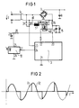
- an actuation pulse for the triac 2 is emitted to an output terminal 22 of the control device 3 with every half-wave of the mains AC voltage U after a zero crossing. This happens more and more delayed, until after about 500 msec, ie at a 50 Hertz mains frequency after 50 half-waves, the process is finished. In this way, a phase control is achieved, as is shown in principle in FIG. 2.
- the AC line voltage is denoted by U and the voltage drop across the demagnetizing winding 1 is denoted by U E.
- U E the voltage drop across the demagnetizing winding 1
- the control device 3 receives information on the zero crossings of the AC line voltage U at an input terminal 23.
- the input terminal 23 is connected to the resistors 31, 30 with the highest possible resistance and the switching device 4 to the Input terminals 5 and 6 of the AC line voltage source U switched.
- the voltage supply for the control device 3 takes place via the terminals 20 and 21, the terminal 21 being at reference potential and the terminal 20 being connected to the input terminal 6 via a resistor and the switching device 4.
- the terminal 20 of the control device 3 is connected to the cathode of a zener diode 15, the anode of which is at reference potential.
- a capacitor 17 is connected in parallel with this zener diode 15.
- the demagnetizing winding 1 is supplied with a decaying alternating current, immediately after the switching device 4 is switched on. This is always the case when the television set is brought from the off state into the on state.
- the control device 3 has a further input 24, which is connected to the output 27 of a remote control receiver, for. B. an infrared preamplifier with a downstream demodulator.
- This remote control receiver 10 is supplied with voltage via terminals 25 and 26, z. B. the terminal 26 is connected to reference potential and the terminal 25 via an RC element 28, 29 to the cathode of the Zener diode 15.
- the control device 3 As soon as the reception of a switch-on command of a remote control is detected in the remote control receiver 10, the control device 3 generates at its output 22 a signal for driving the light-emitting diode 40 in a pulsed manner, as explained above, whereby the light-sensitive triac 2 can be ignited again in such a way that a phase control of the mains AC voltage is ensured is.
- the television set it is then no longer necessary, as in the prior art, to switch the television set off via the switching device 4 in order to switch it on again. Rather, with the device according to the invention for demagnetizing the picture tube, the television set is demagnetized even after being switched on from standby mode.
- control device 3 is switched to reference potential, as shown by way of example in FIG. 1, a potential-free control of the controllable semiconductor switching element 2 is necessary. As shown in FIG. 1, this can be done by an optical control but also by a control familiar to the person skilled in the art by means of an ignition transformer. As a controllable semiconductor switching element would, for. B. also two antiparallel connected thyristors or transistors can be used.
- FIG 3 shows a second exemplary embodiment of a device according to the invention for demagnetizing a picture tube with a two-part demagnetizing winding 1 a, 1 b, the center tap of which is at reference potential.
- a floating control of the controllable semiconductor switching element 2 is no longer necessary.
- FIG 3 shows a device for demagnetizing a picture tube, which is characterized in that the demagnetizing winding has a center tap and two outer connections, that the outer connections are each connected to a cathode connection of a diode, the anode connections of which are parallel to the terminals via the switching device lie, and that the controllable semiconductor switching element is connected with its load path between the center tap and a reference potential.
Abstract
Description
Die Erfindung betrifft eine Einrichtung zur Entmagnetisierung einer Bildröhre mit den Merkmalen des Oberbegriffs des Anspruchs 1.The invention relates to a device for demagnetizing a picture tube with the features of the preamble of claim 1.
Aus "Fernsehtechnik ohne Ballast" von Otto Limann, 13. Auflage, Franzis-Verlag, 1979, Seite 308 ist es bekannt, daß trotz sorgfältigster Konvergenzeinstellungen bei Farbbildröhren Farbfehler auf dem Bildschirm entstehen, wenn die Lochmaske und die am Kolbenrand der Bildröhre angeordnete Eisenabschirmung durch Fremdfelder magnetisch wird. Dazu genügt unter Umständen bereits das Magnetfeld der Erde oder nahe am Bildschirm vorbeibewegte Haushaltsgegenstände, wie z. B. Staubsauger. Ein noch so schwaches Magnetfeld an diesen Eisenteilen hat aber die Neigung, die Elektronenstrahlen in der Bildröhre abzulenken, wodurch die erwähnten Farbfehler entstehen.From "Fernsehtechnik ohne Ballast" by Otto Limann, 13th edition, Franzis-Verlag, 1979, page 308, it is known that, despite the most careful convergence settings in color picture tubes, color errors occur on the screen when the shadow mask and the iron shield arranged on the piston rim of the picture tube show through Foreign fields become magnetic. The magnetic field of the earth or household objects moving close to the screen, e.g. B. vacuum cleaner. However weak a magnetic field on these iron parts tends to deflect the electron beams in the picture tube, which causes the color errors mentioned.
Um dies zu vermeiden, sieht man für Farbbildröhren eine automatische Entmagnetisierung bei jedem Einschalten des Empfangsgerätes vor. Zu diesem Zweck befindet sich am Kolbenrand der Bildröhre eine Entmagnetisierungswicklung, die über einen ersten Kaltleiter mit der Netzwechselspannung verbunden ist. Beim Einschalten des die Bildröhre enthaltenen Gerätes, insbesondere eines Fernsehgerätes, fließt über diesen Kaltleiter und über die Entmagnetisierungswicklung ein ziemlich hoher Wechselstrom. Der Kaltleiter heizt sich durch den Strom auf, sein Widerstandswert wird größer und der Strom nimmt stetig ab, wie dies für eine wirksame Entmagnetisierung erforderlich ist. Das allein genügt jedoch auf die Dauer nicht, um dann den Strom durch die Entmagnetisierungsspule so klein zu halten, daß das Magnetfeld keine Bildstörungen verursacht. Deshalb ist in engem Wärmekontakt mit dem obenerwähnten Kaltleiter ein zweiter Kaltleiter vorgesehen, der parallel zur Netzwechselspannung liegt. Dieser zweite Kaltleiter erwärmt sich beim Einschalten der Netzwechselspannung ebenfalls und heizt dadurch den ersten Kaltleiter so auf, daß nur noch ein extrem kleiner Strom durch die Entmagnetisierungswicklung fließen kann.To avoid this, automatic demagnetization is provided for color picture tubes each time the receiver is switched on. For this purpose, there is a demagnetization winding on the edge of the piston of the picture tube, which winding is connected to the AC mains voltage via a first PTC thermistor. When the device containing the picture tube, in particular a television set, is switched on, a fairly high alternating current flows through this PTC thermistor and via the demagnetization winding. The PTC thermistor heats up due to the current, its resistance value increases and the current decreases continuously, as is necessary for effective demagnetization. In the long run, however, this alone is not enough to keep the current through the demagnetizing coil so small that the magnetic field does not cause any image interference. Therefore, a second PTC thermistor is provided in close thermal contact with the above-mentioned PTC thermistor, which is parallel to the AC mains voltage. This second PTC thermistor also heats up when the mains AC voltage is switched on, thereby heating the first PTC thermistor so that only an extremely small current can flow through the demagnetization winding.
Eine derartige Entmagnetisierungsschaltung für Farbbildröhren wird heute nahezu in jedem Farbfernsehgerät verwendet.Such a demagnetization circuit for color picture tubes is used today in almost every color television set.
Problematisch bei dieser bekannten Entmagnetisierungsschaltung ist die Tatsache, daß die Kaltleiter und die Entmagnetisierungswicklung bei eingeschaltetem Gerät ständig an der Netzwechselspannung liegen und damit kontinuierlich eine Leistung von etwa 3 Watt verbrauchen, um heiß und damit hochohmig zu bleiben. Dies ist besonders im Stand-by-Betrieb von Fernsehgeräten störend, da in diesem Zustand der Netzschalter geschlossen ist. Die Leistungsaufnahme im Stand-byBetrieb eines Fernsehgerätes kann demnach entgegen der Forderung nach möglichst geringer Leistungsaufnahme nicht beliebig reduziert werden.The problem with this known demagnetization circuit is the fact that the PTC thermistor and the demagnetization winding are constantly connected to the mains AC voltage when the device is switched on and thus continuously consume an output of approximately 3 watts in order to remain hot and thus high-impedance. This is particularly annoying in the stand-by mode of television sets, since the power switch is closed in this state. The power consumption in the stand-by mode of a television set cannot therefore be arbitrarily reduced, contrary to the demand for the lowest possible power consumption.
Ein weiterer Nachteil bei dieser bekannten Entmagnetisierungsschaltung ist die Tatsache, daß die Entmagnetisierung nur nach einem Einschalten des Netzschalters des Gerätes wirksam ist. Nur beim Einschalten des Gerätes wird ein abklingender Wechselstrom durch die Entmagnetisierungswicklung geschickt. Nachdem sich die Kaltleiter einmal aufgeheizt haben, ist eine Entmagnetisierung der Bildröhre ohne den Netzschalter betätigen zu müssen, nicht mehr möglich. Dies ist insbesondere dann problematisch, wenn sich das Fernsehgerät im Stand-by-Betrieb befindet und ein Störfeld die am Kolben der Bildröhre angeordnete Eisenabschirmung magnetisiert. So ist z. B. beim Einschalten des Fernsehgerätes über eine Fernbedienung aus dem Stand-by-Betrieb eine Entmagnetisierung der Bildröhre nicht mehr möglich.Another disadvantage of this known demagnetization circuit is the fact that the demagnetization is only effective after the mains switch of the device has been switched on. A decaying alternating current is only sent through the demagnetization winding when the device is switched on. After the PTC thermistor has heated up, it is no longer possible to demagnetize the picture tube without having to press the power switch. This is particularly problematic when the television is in stand-by mode and an interference field magnetizes the iron shield arranged on the piston of the picture tube. So z. B. when switching on the TV using a remote control from standby mode, demagnetization of the picture tube is no longer possible.
Der Erfindung liegt die Aufgabe zugrunde, eine Einrichtung zur Entmagnetisierung einer Bildröhre anzugeben, die sich durch eine reduzierte Leistungsaufnahme auszeichnet und auch dann aktivierbar ist, wenn das Fernsehgerät vom Stand-by- Betrieb aus eingeschaltet wird.The invention has for its object to provide a device for demagnetizing a picture tube, which is characterized by a reduced power consumption and can also be activated when the television set is switched on from stand-by mode.
Diese Aufgabe wird durch die kennzeichnenden Merkmale des Anspruchs 1 gelöst.This object is achieved by the characterizing features of claim 1.
Weiterbildungen der Erfindung sind Gegenstand der Unteransprüche.Developments of the invention are the subject of the dependent claims.
Die Erfindung wird im folgenden anhand von drei Figuren näher erläutert. Es Zeigen:
- FIG 1 ein erstes erfindungsgemäßes Ausführungsbeispiel der Einrichtung zur Entmagnetisierung einer Farbbildröhre mit einem optisch ansteuerbaren Triac als steuerbares Halbleiterschaltelement, und
- FIG 2 Verlauf der Netzwechselspannung und der an der Entmagnetisierungswicklung von FIG 1 anliegenden Spannung bei Phasenanschnittsteuerung durch das steuerbare Halbleiterschaltelement, und
- FIG 3 ein zweites Ausführungsbeispiel einer erfindungsgemäßen Einrichtung zur Entmagnetisierung einer Farbbildröhre mit zweigeteilter Entmagnetisierungswicklung.
- FIG 1 zeigt den prinzipiellen Aufbau der Einrichtung zur Entmagnetisierung einer der besseren Übersichtlichkeit wegen nicht dargestellten Bildröhre eines Farbfernsehgerätes. Die Einrichtung weist zwei
Eingangsklemmen 5 und 6 zum Anschluß einer Netzwechselspannungsquelle U auf, welche über eine als Netzschalter wirkende Schalteinrichtung 4 der Reihenschaltung einer Entmagnetisierungswicklung 1 und einemsteuerbaren Halbleiterschaltelement 2 zugeführt wird. In diesem Ausführungsbeispiel ist dassteuerbare Halbleiterschaltelement 2 ein lichtsteuerbarer Triac.
- 1 shows a first exemplary embodiment according to the invention of the device for demagnetizing a color picture tube with an optically controllable triac as a controllable semiconductor switching element, and
- FIG. 2 curve of the AC mains voltage and the voltage applied to the demagnetizing winding of FIG. 1 with phase control by the controllable semiconductor switching element, and
- 3 shows a second exemplary embodiment of a device according to the invention for demagnetizing a color picture tube with a two-part demagnetizing winding.
- 1 shows the basic structure of the device for demagnetizing one of the better clarity due to the picture tube, not shown, of a color television set. The device has two
input terminals semiconductor switching element 2 via a switching device 4 acting as a mains switch. In this exemplary embodiment, the controllablesemiconductor switching element 2 is a light-controllable triac.
Parallel zur Reihenschaltung des lichtsteuerbaren Triacs 2 und der Entmagnetisierungswicklung 1 liegen die beiden Eingänge eines Brückengleichrichters 7, zwischen dessen Ausgängen ein Kondensator 8 geschaltet ist, an dem eine gleichgerichtete Spannung zur Versorgung weiterer Schaltungskomponenten des Fernsehgerätes abgreifbar ist.Parallel to the series connection of the light-
Der lichtsteuerbare Triac 2 wird impulsweise von Licht, das von einer Leuchtdiode 40 ausgestrahlt wird, angesteuert, wodurch der Triac 2 zünden kann. Dieser Triac 2 schaltet, sofern die Schalteinrichtung 4 geschlossen ist, den Strom I durch die Entmagnetisierungswicklung 1.The light-
Beginnend mit dem Einschalten der Schalteinrichtung 4 wird ein Ansteuerimpuls für den Triac 2 bei jeder Halbwelle der Netzwechselspannung U nach einem Nulldurchgang an eine Ausgangsklemme 22 der Steuereinrichtung 3 abgegeben. Dies geschieht immer mehr verzögert, bis nach etwa 500 msec, d. h. bei einer 50 Hertz-Netzwechselfrequenz nach 50 Halbwellen, der Vorgang beendet ist. Dadurch wird eine Phasenanschnittsteuerung erreicht, wie diese prinzipiell in FIG 2 dargestellt ist. Dort wird die Netzwechselspannung mit U und die an der Entmagnetisierungswicklung 1 abfallende Spannung mit UE bezeichnet. Ergebnis ist ein durch die Entmagnetisierungswicklung 1 fließender effektiv abklingender Strom, der ein - wie bei der Entmagnetisierung eingangs gefordert - abklingendes Wechselmagnetfeld in der Entmagnetisierungswicklung 1 hervorruft.Starting with the switching on of the switching device 4, an actuation pulse for the
Um an den Ausgang 22 der Steuereinrichtung 3 zur Phasenanschnittsteuerung geeignete Impulse anlegen zu können, erhält die Steuereinrichtung 3 an einer Eingangsklemme 23 Informationen über die Nulldurchgänge der Netzwechselspannung U. Dazu ist die Eingangsklemme 23 über möglichst hochohmige Widerstände 31, 30 und die Schalteinrichtung 4 an die Eingangsklemmen 5 und 6 der Netzwechselspannungsquelle U geschaltet. Die Spannungsversorgung für die Steuereinrichtung 3 erfolgt über die Klemmen 20 und 21, wobei die Klemme 21 auf Bezugspotential liegt und die Klemme 20 über einen Widerstand und die Schalteinrichtung 4 an die Eingangsklemme 6 geschaltet ist. Zugleich ist die Klemme 20 der Steuereinrichtung 3 an die Kathode einer Zenerdiode 15 geschaltet, deren Anode auf Bezugspotential liegt. Parallel zu dieser Zenerdiode 15 ist ein Kondensator 17 geschaltet.In order to be able to apply suitable pulses to the
Wie oben beschrieben, wird die Entmagnetisierungswicklung 1 mit einem abklingenden Wechselstrom beaufschlagt und zwar unmittelbar nach dem Einschalten der Schalteinrichtung 4. Dies ist immer dann der Fall, wenn das Fernsehgerät vom AusZustand in den Ein-Zustand gebracht wird.As described above, the demagnetizing winding 1 is supplied with a decaying alternating current, immediately after the switching device 4 is switched on. This is always the case when the television set is brought from the off state into the on state.
Damit die Bildröhre des Fernsehgeräts aber auch beim Einschalten aus einem Stand-by-Betrieb entmagnetisiert werden kann, weist die Steuereinrichtung 3 einen weiteren Eingang 24 auf, der mit dem Ausgang 27 eines Fernbedienungsempfängers, z. B. eines Infrarot-Vorverstärkers mit nachgeschaltetem Demodulator, verbunden ist. Dieser Fernbedienungsempfänger 10 wird über Klemmen 25 und 26 mit Spannung versorgt, wobei z. B. die Klemme 26 auf Bezugspotential und die Klemme 25 über ein RC-Glied 28, 29 an die Kathode der Zenerdiode 15 angeschlossen ist.So that the picture tube of the television can also be demagnetized when switched on from a standby mode, the
Sobald im Fernsteuerempfänger 10 der Empfang eines Einschaltbefehles einer Fernbedienung detektiert wird, erzeugt die Steuereinrichtung 3 an ihrem Ausgang 22 ein Signal zum wie oben ausgeführt impulsweisen Ansteuern der Leuchtdiode 40, wodurch der lichtempfindliche Triac 2 wieder so gezündet werden kann, daß eine Phasenanschnittsteuerung der Netzwechselspannung gewahrleistet ist. Damit ist es aber dann zum Zwecke der Entmagnetisierung nicht mehr wie beim Stand der Technik notwendig, das Fernsehgerät über die Schalteinrichtung 4 auszuschalten, um dieses anschließend wieder einzuschalten. Vielmehr wird mit der erfindungsgemäßen Einrichtung zur Entmagnetisierung der Bildröhre das Fernsehgerät auch nach einem Einschalten aus dem Stand-by-Betrieb entmagnetisiert.As soon as the reception of a switch-on command of a remote control is detected in the
Sofern die Steuereinrichtung 3 auf Bezugspotential geschaltet ist, wie dies FIG 1 beispielhaft zeigt, ist eine potentialfreie Ansteuerung des steuerbaren Halbleiterschaltelementes 2 notwendig. Diese kann wie in FIG 1 gezeigt, durch eine optische Ansteuerung aber auch durch eine dem Fachmann geläufige Ansteuerung mittels Zündübertrager erfolgen. Als steuerbares Halbleiterschaltelement wären z. B. auch zwei antiparallel geschaltete Thyristoren oder Transistoren einsetzbar.If the
FIG 3 zeigt ein zweites Ausführungsbeispiel einer erfindungsgemäßen Einrichtung zur Entmagnetisierung einer Bildröhre mit einer zweigeteilten Entmagnetisierungswicklung 1 a, 1 b, deren Mittenanzapfung auf Bezugspotential liegt. Bei dieser Anordnung ist eine potentialfreie Ansteuerung des steuerbaren Halbleiterschaltelementes 2 nicht mehr notwendig. Im einzelnen zeigt FIG 3 eine Einrichtung zur Entmagnetisierung einer Bildröhre, die sich dadurch auszeichnet, daß die Entmagnetisierungswicklung eine Mittelanzapfung und zwei äußere Anschlüsse aufweist, daß die äußeren Anschlüsse an jeweils einen Kathodenanschluß einer Diode angeschlossen sind, deren Anodenanschlüsse über die Schalteinrichtung parallel zu den Klemmen liegen, und daß das steuerbare Halbleiterschaltelement mit seiner Laststrecke zwischen die Mittelanzapfung und ein Bezugspotential geschaltet ist.3 shows a second exemplary embodiment of a device according to the invention for demagnetizing a picture tube with a two-part demagnetizing winding 1 a, 1 b, the center tap of which is at reference potential. With this arrangement, a floating control of the controllable
Claims (10)
gekennzeichnet durch
ein von einer Steuereinrichtung (3) steuerbares Halbleiterschaltelement (2), durch das der Wechselstrom phasenanschnittgesteuert an die Entmagnetisierungswicklung (1) gelegt wird.1. Device for demagnetizing a picture tube with a demagnetizing winding (1) which is arranged on the piston edge of the picture tube and can be acted upon by an alternating current obtained and decaying from an alternating voltage source (U),
marked by
A semiconductor switching element (2) which can be controlled by a control device (3) and through which the alternating current is applied to the demagnetizing winding (1) in a phase-controlled manner.
dadurch gekennzeichnet,
daß die Entmagnetisierungswicklung (1) und das steuerbare Halbleiterschaltelement (2) in Reihe geschaltet und über eine Schalteinrichtung (4) mit Klemmen (5, 6) zum Anschluß der Netzwechselspannungsquelle (U) verbunden sind.2. Device for demagnetizing a picture tube according to claim 1,
characterized,
that the demagnetization winding (1) and the controllable semiconductor switching element (2) are connected in series and are connected via a switching device (4) to terminals (5, 6) for connecting the mains AC voltage source (U).
dadurch gekennzeichnet,
daß die Entmagnetisierungswicklung (1) eine Mittelanzapfung (40) und zwei äußere Anschlüsse (41, 42) aufweist, daß die äußeren Anschlüsse (41, 42) an jeweils einen Kathodenanschluß einer Diode (43, 44) angeschlossen sind, deren Anodenanschlüsse über die Schalteinrichtung (4) parallel zu den Klemmen (5, 6) liegen, und daß das steuerbare Halbleiterschaltelement (1) mit seiner Laststrecke zwischen die Mittelanzapfung (40) und ein Bezugspotential (45) geschaltet ist.3. Device for demagnetizing a picture tube according to claim 1,
characterized,
that the demagnetizing winding (1) has a center tap (40) and two outer connections (41, 42), that the outer connections (41, 42) are each connected to a cathode connection of a diode (43, 44), the anode connections of which via the switching device (4) are parallel to the terminals (5, 6), and that the controllable semiconductor switching element (1) is connected with its load path between the center tap (40) and a reference potential (45).
dadurch gekennzeichnet,
daß das steuerbare Halbleiterschaltelement (2) potentialfrei mit der Steuereinrichtung (3) verbunden ist.4. Device for demagnetizing a picture tube according to claim 1 or 4,
characterized,
that the controllable semiconductor switching element (2) is potential-free connected to the control device (3).
dadurch gekennzeichnet, daß das steuerbare Halbleiterschaltelement (2) von der Steuereinrichtung (3) mit optischen Mitteln ansteuerbar ist.5. Device for demagnetizing a picture tube according to claim 4,
characterized in that the controllable semiconductor switching element (2) can be controlled by the control device (3) with optical means.
dadurch gekennzeichnet,
daß das steuerbare Halbleiterschaltelement (2) von der Steuereinrichtung (3) über einen Übertrager (7) ansteuerbar ist.6. Device for demagnetizing a picture tube according to claim 4,
characterized,
that the controllable semiconductor switching element (2) can be controlled by the control device (3) via a transformer (7).
dadurch gekennzeichnet,
daß das steuerbare Halbleiterschaltelement (2) ein Triac ist.7. Device for demagnetizing a picture tube according to one of claims 1 to 6,
characterized,
that the controllable semiconductor switching element (2) is a triac.
dadurch gekennzeichnet,
daß das steuerbare Halbleiterschaltelement (2) ein lichtempfindlicher Triac ist.8. Device for demagnetizing a picture tube according to claim 5 and 7,
characterized,
that the controllable semiconductor switching element (2) is a light-sensitive triac.
daß das steuerbare Halbleiterschaltelement (2) ein Transistor oder Thyristor ist.9. Device for demagnetizing a picture tube according to one of claims 1 to 6, characterized in that
that the controllable semiconductor switching element (2) is a transistor or thyristor.
daß die Steuereinrichtung (3) mit einem Fernbedienungsempfänger (10) verbunden ist, wobei die Steuereinrichtung (3) dann das steuerbare Halbleiterschaltelement (1) ansteuert, nachdem ein Fernbedienungsbefehl zum Einschalten der Bildröhre aus einem Stand-by- Betrieb empfangen wird.10. Device for demagnetizing a picture tube according to one of claims 1 to 9, characterized in that
that the control device (3) is connected to a remote control receiver (10), the control device (3) then controlling the controllable semiconductor switching element (1) after a remote control command to switch on the picture tube is received from a standby mode.
Priority Applications (1)
| Application Number | Priority Date | Filing Date | Title |
|---|---|---|---|
| EP90118415A EP0477399A1 (en) | 1990-09-25 | 1990-09-25 | Device for demagnetizing a picture tube |
Applications Claiming Priority (1)
| Application Number | Priority Date | Filing Date | Title |
|---|---|---|---|
| EP90118415A EP0477399A1 (en) | 1990-09-25 | 1990-09-25 | Device for demagnetizing a picture tube |
Publications (1)
| Publication Number | Publication Date |
|---|---|
| EP0477399A1 true EP0477399A1 (en) | 1992-04-01 |
Family
ID=8204512
Family Applications (1)
| Application Number | Title | Priority Date | Filing Date |
|---|---|---|---|
| EP90118415A Withdrawn EP0477399A1 (en) | 1990-09-25 | 1990-09-25 | Device for demagnetizing a picture tube |
Country Status (1)
| Country | Link |
|---|---|
| EP (1) | EP0477399A1 (en) |
Cited By (3)
| Publication number | Priority date | Publication date | Assignee | Title |
|---|---|---|---|---|
| DE4237634A1 (en) * | 1992-11-07 | 1994-05-11 | Nokia Deutschland Gmbh | Video receiving device with a switching power supply |
| WO1995007006A1 (en) * | 1993-08-31 | 1995-03-09 | Instrumentacion Electronica Promax, S.A. | Sequential demagnetization circuit |
| WO1998059499A1 (en) * | 1997-06-25 | 1998-12-30 | Koninklijke Philips Electronics N.V. | Degaussing |
Citations (2)
| Publication number | Priority date | Publication date | Assignee | Title |
|---|---|---|---|---|
| US4262232A (en) * | 1979-11-30 | 1981-04-14 | Rca Corp. | Color television degaussing circuit |
| DE3831306A1 (en) * | 1988-09-15 | 1990-03-29 | Vogt Electronic Ag | Demagnetisation circuit |
-
1990
- 1990-09-25 EP EP90118415A patent/EP0477399A1/en not_active Withdrawn
Patent Citations (2)
| Publication number | Priority date | Publication date | Assignee | Title |
|---|---|---|---|---|
| US4262232A (en) * | 1979-11-30 | 1981-04-14 | Rca Corp. | Color television degaussing circuit |
| DE3831306A1 (en) * | 1988-09-15 | 1990-03-29 | Vogt Electronic Ag | Demagnetisation circuit |
Non-Patent Citations (2)
| Title |
|---|
| PATENT ABSTRACTS OF JAPAN, Band 1, Nr. 146 (E-068), 26. November 1977; & JP-A-52 084 919 (SANYO DENKI K.K.) 14-07-1977 * |
| PATENT ABSTRACTS OF JAPAN, Band 3, Nr. 78 (E-121), 5. Juli 1979; & JP-A-54 056 325 (MATSUSHITA DENKI SANGYO K.K.) 07-05-1979 * |
Cited By (7)
| Publication number | Priority date | Publication date | Assignee | Title |
|---|---|---|---|---|
| DE4237634A1 (en) * | 1992-11-07 | 1994-05-11 | Nokia Deutschland Gmbh | Video receiving device with a switching power supply |
| EP0598267A2 (en) * | 1992-11-07 | 1994-05-25 | NOKIA TECHNOLOGY GmbH | Television receiver with a switching power supply |
| EP0598267A3 (en) * | 1992-11-07 | 1994-06-15 | Nokia Technology Gmbh | Television receiver with a switching power supply. |
| WO1995007006A1 (en) * | 1993-08-31 | 1995-03-09 | Instrumentacion Electronica Promax, S.A. | Sequential demagnetization circuit |
| ES2078860A2 (en) * | 1993-08-31 | 1995-12-16 | Instrumentacion Electronica Pr | Sequential demagnetization circuit |
| WO1998059499A1 (en) * | 1997-06-25 | 1998-12-30 | Koninklijke Philips Electronics N.V. | Degaussing |
| US5940261A (en) * | 1997-06-25 | 1999-08-17 | U.S. Philips Corporation | Circuit and method independent of frequency and voltage deviations of supply voltage, and display apparatus incorporating same circuit |
Similar Documents
| Publication | Publication Date | Title |
|---|---|---|
| DE3118816C2 (en) | Degaussing circuit for a color television | |
| DE69835328T2 (en) | Control circuit for a fluorescent lamp | |
| EP0477399A1 (en) | Device for demagnetizing a picture tube | |
| DE3044917C2 (en) | Degaussing circuit for a color television receiver | |
| EP0492314B1 (en) | Demagnetisation circuit for the picture tube in a television receiver | |
| DE2437633C3 (en) | Voltage regulating circuit for a deflection circuit | |
| EP0354321B1 (en) | Circuit arrangement for degaussing the shadow mask in a colour picture tube | |
| DE2313961B1 (en) | Line deflection Sc line arrangement for cathode ray tubes | |
| DE4219958C1 (en) | Ballast circuit for discharge lamp - uses phase gate control to short out electrodes for interval in each half cycle, depending on brightness | |
| DE19855457A1 (en) | Demagnetization circuit for television receiver or color monitor | |
| EP0275960A2 (en) | Circuit arrangement for an inductive load | |
| DE3418076C2 (en) | Circuit arrangement for the automatic demagnetization of the picture tube in a color television receiver | |
| DE2835611A1 (en) | Demagnetising circuit for colour TV receivers tube - has series LC circuit shunted by semiconductor switch connected via resistor network, producing grid voltages for triple beam tube | |
| DE10014383C2 (en) | degaussing | |
| EP0598267A2 (en) | Television receiver with a switching power supply | |
| DE1275104B (en) | Self-oscillating horizontal deflection circuit, especially for television receivers | |
| DE2315497A1 (en) | BRIGHTNESS CONTROL CIRCUIT FOR GAS DISCHARGE LAMPS | |
| EP0471228A1 (en) | Starter for fluorescent lamps | |
| DE1811526A1 (en) | Control circuit for the energy supply of an electrical consumer | |
| DE2835613A1 (en) | Demagnetising circuit for colour TV CRT - connects capacitor to coil by relay whose excitation coil is connected to heating filament and transformer secondary tapping | |
| EP0391032B1 (en) | Degaussing circuit for a picture tube in a video display apparatus | |
| DE3040365A1 (en) | Rapid semiconductor switching control - has base current matched to load for maintaining minimum current consumption | |
| CH595036A5 (en) | Fluorescent lamp control circuit | |
| DE1811048A1 (en) | High frequency power supply circuit | |
| DE2647266A1 (en) | AC power supply circuit for halogen lamp LV photo enlarger - has timing circuit controlling thyristor bridge that feeds voltage stabiliser |
Legal Events
| Date | Code | Title | Description |
|---|---|---|---|
| PUAI | Public reference made under article 153(3) epc to a published international application that has entered the european phase |
Free format text: ORIGINAL CODE: 0009012 |
|
| 17P | Request for examination filed |
Effective date: 19901205 |
|
| AK | Designated contracting states |
Kind code of ref document: A1 Designated state(s): AT BE CH DE DK ES FR GB GR IT LI LU NL SE |
|
| RBV | Designated contracting states (corrected) |
Designated state(s): DE ES FR GB IT |
|
| STAA | Information on the status of an ep patent application or granted ep patent |
Free format text: STATUS: THE APPLICATION IS DEEMED TO BE WITHDRAWN |
|
| 18D | Application deemed to be withdrawn |
Effective date: 19940401 |