EP0597952B1 - Polymerisationsreaktor - Google Patents
Polymerisationsreaktor Download PDFInfo
- Publication number
- EP0597952B1 EP0597952B1 EP92916645A EP92916645A EP0597952B1 EP 0597952 B1 EP0597952 B1 EP 0597952B1 EP 92916645 A EP92916645 A EP 92916645A EP 92916645 A EP92916645 A EP 92916645A EP 0597952 B1 EP0597952 B1 EP 0597952B1
- Authority
- EP
- European Patent Office
- Prior art keywords
- reactor
- tubes
- liquid
- coolant
- tube bundle
- Prior art date
- Legal status (The legal status is an assumption and is not a legal conclusion. Google has not performed a legal analysis and makes no representation as to the accuracy of the status listed.)
- Expired - Lifetime
Links
- 238000006116 polymerization reaction Methods 0.000 title abstract description 14
- 239000002826 coolant Substances 0.000 claims abstract description 26
- 239000003054 catalyst Substances 0.000 claims abstract description 16
- 239000007788 liquid Substances 0.000 claims description 41
- 239000000376 reactant Substances 0.000 claims description 8
- 239000007787 solid Substances 0.000 claims description 6
- 239000012530 fluid Substances 0.000 claims description 5
- 238000001816 cooling Methods 0.000 claims description 3
- -1 semisolids Substances 0.000 claims description 2
- 238000000638 solvent extraction Methods 0.000 claims 2
- 239000002002 slurry Substances 0.000 abstract description 30
- 229920000642 polymer Polymers 0.000 abstract description 18
- 238000006243 chemical reaction Methods 0.000 abstract description 14
- 239000000203 mixture Substances 0.000 abstract description 11
- 239000003507 refrigerant Substances 0.000 abstract description 8
- 239000000126 substance Substances 0.000 abstract description 7
- 229920001971 elastomer Polymers 0.000 abstract description 6
- 238000004519 manufacturing process Methods 0.000 abstract description 6
- 238000009826 distribution Methods 0.000 abstract description 5
- 229920005549 butyl rubber Polymers 0.000 abstract description 4
- 239000000806 elastomer Substances 0.000 abstract description 4
- 238000005086 pumping Methods 0.000 abstract description 3
- 239000000178 monomer Substances 0.000 abstract description 2
- 238000013461 design Methods 0.000 description 14
- 238000012546 transfer Methods 0.000 description 13
- 238000009835 boiling Methods 0.000 description 10
- VGGSQFUCUMXWEO-UHFFFAOYSA-N Ethene Chemical group C=C VGGSQFUCUMXWEO-UHFFFAOYSA-N 0.000 description 7
- 230000000694 effects Effects 0.000 description 6
- 239000011541 reaction mixture Substances 0.000 description 6
- 239000005977 Ethylene Substances 0.000 description 5
- 239000003085 diluting agent Substances 0.000 description 5
- 125000000484 butyl group Chemical group [H]C([*])([H])C([H])([H])C([H])([H])C([H])([H])[H] 0.000 description 4
- 229930195733 hydrocarbon Natural products 0.000 description 4
- 150000002430 hydrocarbons Chemical class 0.000 description 4
- VQTUBCCKSQIDNK-UHFFFAOYSA-N Isobutene Chemical group CC(C)=C VQTUBCCKSQIDNK-UHFFFAOYSA-N 0.000 description 3
- 150000001993 dienes Chemical class 0.000 description 3
- 238000000034 method Methods 0.000 description 3
- 239000002994 raw material Substances 0.000 description 3
- 239000004215 Carbon black (E152) Substances 0.000 description 2
- 238000005727 Friedel-Crafts reaction Methods 0.000 description 2
- 230000008901 benefit Effects 0.000 description 2
- 238000006482 condensation reaction Methods 0.000 description 2
- 230000008569 process Effects 0.000 description 2
- 239000005060 rubber Substances 0.000 description 2
- 230000009471 action Effects 0.000 description 1
- 230000004913 activation Effects 0.000 description 1
- 229910052782 aluminium Inorganic materials 0.000 description 1
- 230000008859 change Effects 0.000 description 1
- 230000007423 decrease Effects 0.000 description 1
- 238000011161 development Methods 0.000 description 1
- 230000004907 flux Effects 0.000 description 1
- 238000007710 freezing Methods 0.000 description 1
- 230000008014 freezing Effects 0.000 description 1
- 239000011261 inert gas Substances 0.000 description 1
- 238000009434 installation Methods 0.000 description 1
- 229910052751 metal Inorganic materials 0.000 description 1
- 239000002184 metal Substances 0.000 description 1
- 238000013021 overheating Methods 0.000 description 1
- 238000005192 partition Methods 0.000 description 1
- 230000000379 polymerizing effect Effects 0.000 description 1
- 238000011112 process operation Methods 0.000 description 1
- 239000012429 reaction media Substances 0.000 description 1
- 230000009467 reduction Effects 0.000 description 1
- 238000005057 refrigeration Methods 0.000 description 1
- 230000035945 sensitivity Effects 0.000 description 1
- 238000009987 spinning Methods 0.000 description 1
- 229910001220 stainless steel Inorganic materials 0.000 description 1
- 239000010935 stainless steel Substances 0.000 description 1
- 229920003051 synthetic elastomer Polymers 0.000 description 1
- 239000005061 synthetic rubber Substances 0.000 description 1
- 239000011800 void material Substances 0.000 description 1
Images

Classifications
-
- F—MECHANICAL ENGINEERING; LIGHTING; HEATING; WEAPONS; BLASTING
- F28—HEAT EXCHANGE IN GENERAL
- F28F—DETAILS OF HEAT-EXCHANGE AND HEAT-TRANSFER APPARATUS, OF GENERAL APPLICATION
- F28F13/00—Arrangements for modifying heat-transfer, e.g. increasing, decreasing
- F28F13/06—Arrangements for modifying heat-transfer, e.g. increasing, decreasing by affecting the pattern of flow of the heat-exchange media
-
- B—PERFORMING OPERATIONS; TRANSPORTING
- B01—PHYSICAL OR CHEMICAL PROCESSES OR APPARATUS IN GENERAL
- B01F—MIXING, e.g. DISSOLVING, EMULSIFYING OR DISPERSING
- B01F27/00—Mixers with rotary stirring devices in fixed receptacles; Kneaders
- B01F27/80—Mixers with rotary stirring devices in fixed receptacles; Kneaders with stirrers rotating about a substantially vertical axis
- B01F27/91—Mixers with rotary stirring devices in fixed receptacles; Kneaders with stirrers rotating about a substantially vertical axis with propellers
-
- B—PERFORMING OPERATIONS; TRANSPORTING
- B01—PHYSICAL OR CHEMICAL PROCESSES OR APPARATUS IN GENERAL
- B01J—CHEMICAL OR PHYSICAL PROCESSES, e.g. CATALYSIS OR COLLOID CHEMISTRY; THEIR RELEVANT APPARATUS
- B01J19/00—Chemical, physical or physico-chemical processes in general; Their relevant apparatus
- B01J19/0006—Controlling or regulating processes
- B01J19/0013—Controlling the temperature of the process
-
- B—PERFORMING OPERATIONS; TRANSPORTING
- B01—PHYSICAL OR CHEMICAL PROCESSES OR APPARATUS IN GENERAL
- B01J—CHEMICAL OR PHYSICAL PROCESSES, e.g. CATALYSIS OR COLLOID CHEMISTRY; THEIR RELEVANT APPARATUS
- B01J19/00—Chemical, physical or physico-chemical processes in general; Their relevant apparatus
- B01J19/18—Stationary reactors having moving elements inside
- B01J19/1868—Stationary reactors having moving elements inside resulting in a loop-type movement
- B01J19/1875—Stationary reactors having moving elements inside resulting in a loop-type movement internally, i.e. the mixture circulating inside the vessel such that the upwards stream is separated physically from the downwards stream(s)
-
- C—CHEMISTRY; METALLURGY
- C08—ORGANIC MACROMOLECULAR COMPOUNDS; THEIR PREPARATION OR CHEMICAL WORKING-UP; COMPOSITIONS BASED THEREON
- C08F—MACROMOLECULAR COMPOUNDS OBTAINED BY REACTIONS ONLY INVOLVING CARBON-TO-CARBON UNSATURATED BONDS
- C08F210/00—Copolymers of unsaturated aliphatic hydrocarbons having only one carbon-to-carbon double bond
- C08F210/04—Monomers containing three or four carbon atoms
- C08F210/08—Butenes
- C08F210/10—Isobutene
- C08F210/12—Isobutene with conjugated diolefins, e.g. butyl rubber
-
- B—PERFORMING OPERATIONS; TRANSPORTING
- B01—PHYSICAL OR CHEMICAL PROCESSES OR APPARATUS IN GENERAL
- B01F—MIXING, e.g. DISSOLVING, EMULSIFYING OR DISPERSING
- B01F27/00—Mixers with rotary stirring devices in fixed receptacles; Kneaders
- B01F27/05—Stirrers
- B01F27/11—Stirrers characterised by the configuration of the stirrers
- B01F27/15—Stirrers with tubes for guiding the material
-
- B—PERFORMING OPERATIONS; TRANSPORTING
- B01—PHYSICAL OR CHEMICAL PROCESSES OR APPARATUS IN GENERAL
- B01J—CHEMICAL OR PHYSICAL PROCESSES, e.g. CATALYSIS OR COLLOID CHEMISTRY; THEIR RELEVANT APPARATUS
- B01J2219/00—Chemical, physical or physico-chemical processes in general; Their relevant apparatus
- B01J2219/00049—Controlling or regulating processes
- B01J2219/00051—Controlling the temperature
- B01J2219/00074—Controlling the temperature by indirect heating or cooling employing heat exchange fluids
- B01J2219/00076—Controlling the temperature by indirect heating or cooling employing heat exchange fluids with heat exchange elements inside the reactor
- B01J2219/00085—Plates; Jackets; Cylinders
Definitions
- This invention relates to an improved chemical reactor, especially a polymerization reactor.
- it relates to a novel, improved back-mixed chemical reactor useful in the production of butyl rubber.
- Reactors are of various designs, the form and shape thereof depending largely on the nature of the reaction to be conducted therein.
- a reaction mixture is circulated as a slurry in a reactor into which reactants and catalysts are injected, and product withdrawn.
- a back-mixed reactor is employed; typically a one-tube pass system as described by reference to U.S. 2,474,592.
- Such reactor is characterized generally as a vertically oriented elongate vessel formed by an enclosing side wall within which is provided an axially mounted draft tube of relatively large diameter surrounded by a relatively large number of small diameter tubes which extend downwardly from an upper common plane to a lower common plane where the upper and lower terminal ends of the small diameter tubes and draft tube, respectively, terminate.
- An axial flow pump provided with a rotating impeller, which extends into the draft tube within which it is partially housed, is located in the bottom of the reactor to maintain the reaction mixture in a well dispersed state, and pump same up the draft tube; the reaction mixture including the diluent, catalyst, and reactants which are directly introduced into the bottom of the reactor, and a portion of the reaction mixture which after upward transport through the draft tube is recycled from the top of the reactor downwardly through the small diameter tubes which surround the draft tube.
- the outer walls of the reaction vessel form a jacket through which a liquid hydrocarbon coolant is circulated to remove the exothermic heat of reaction via heat exchange contact with the outer walls of the small diameter tubes, and wall of the central draft tube.
- Polymer fouling is another serious problem encountered in this type of reactor. Polymer deposits upon and fouls heat transfer surfaces within the reaction vessel; the polymer adhering tenaciously to the metal surfaces as a continuous film, and in severe cases as large masses of rubber. The reason, or reasons, for this phenomenon is not well understood though, it is known that mass fouling is caused by local overheating. Nonetheless, polymer fouling presents a serious problem and it has greatly limited the usefulness, as well as the efficiency of this type of reactor. For example, it is reported in U.S.
- a further and more specific object is to provide a reactor, as characterized, for catalytically polymerizing liquified isobutylene with a liquified diolefin at low temperatures to form a rubber-like polymer.
- embodying apparatus which comprises an elongate vessel formed by an enclosing side, top and bottom wall, or walls, suitably an enclosing side wall, or walls, a top cover and bottom cover, with inlet and outlets for the introduction of reactants and catalysts, and the removal of product, within which is contained (1) a two-tube pass system, constituted of an inner or center tube bundle through which a mixture or slurry of polymerizable monomers and catalyst is passed in one direction, and recycled via an outer tube bundle in the opposite direction in essentially even flow distribution, (2) while the tubes of the center and outer tubular bundles are maintained within a jacketed section, or sections of the reactor into which a coolant, or refrigerant, is injected and vaporized to remove the heat of reaction.
- a two-tube pass system constituted of an inner or center tube bundle through which a mixture or slurry of polymerizable monomers and catalyst is passed in one direction, and recycled via an outer tube bundle in the opposite direction in essentially even flow distribution
- the coolant, or refrigerant, in heat exchange relationship with the tubes thus removes the exothermic heat of reaction from the polymerization mixture, and maintains the polymerization mixture at uniformly low temperature.
- An even flow circulation of the slurry which aids in maintaining the uniform low temperature, is provided by the use of (3) a diffuser and (4) mixed flow pumping system, with its impeller, by virtue of which an adequate pressure head of even pressure profile is developed across the entry sides of the center tubes to maintain the even flow distribution within the two-tube pass system at high circulation rate.
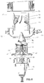
- Figure 1 depicts a sectional side elevation view of a polymerization reactor.
- Figure 2 is a section view taken along line 2-2 of Figure 1.
- Figure 3 is a section view taken along line 3-3 of Figure 1.
- Figure 4 is a section view taken along line 4-4 of Figure 1.
- Figure 5 is a section view taken along line 5-5 of Figure 1.
- Figure 6 is an enlarged. exploded view of the lower portion of the reactor depicted by reference to Figure 1.
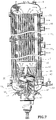
- Figure 7 is an enlarged assembled view of the reactor described in Figure 1.
- FIG. 1 there is shown a polymerization reactor 10 of a vessel formed by an enclosing side wall 11, formed of upper and lower tubular sections 11 1 , 11 2 , respectively, bolted or welded together to form a tubular shell, an enclosing top cover 12 and bottom cover 13 each of which is provided with inlets or outlets, or both, as subsequently described for the introduction or withdrawal of catalyst, chemical raw materials or products.
- a first tube bundle 20 is located at the center of the vessel, the central tube bundle 20 containing a large number (n) of tubes 20 1 , 20 2 --20 n oriented axially to the shell, and arrayed in a convenient pattern (e.g., as a triangle, square, or circular pattern as shown), within the enclosing side wall 11 of the vessel; and the first, or central tube bundle 20 is surrounded by a second tube bundle 30 containing a large number (n) of 30 1 , 30 2 --30 n oriented axially to the shell and arranged in circular array (Figure 5).
- a convenient pattern e.g., as a triangle, square, or circular pattern as shown
- the terminal ends of the tubes of tube bundles 20, 30 extend downwardly from an upper common plane, above which there is provided an enclosed upper reactor space, reactor head or chamber 14, to a lower common plane, below which there is provided a lower reactor space, reactor head or bottom chamber 15 ( Figure 6).
- a mixed flow pump assembly 40 is mounted in the bottom chamber of the vessel, the "impeller” or “pumping end” of the pump being faced upwardly so that a liquid, or slurry, can be pumped upwardly into a passageway of circuitous shape, or design, containing a diffuser 60 which directs the liquid flow into the tubes 20 1 , 20 2 --20 n of the central tube bundle 20.
- the vessel is jacketed and provided with an inlet, or inlets, for the introduction of a coolant, or refrigerant, suitably a liquid coolant, or refrigerant, and an outlet, or outlets, for the removal of the coolant, or refrigerant, suitably as a vapor-liquid mixture to more effectively remove the exothermic heat of reaction.
- the amount of surface area provided by each of the two tubular bundles for heat exchange ranges generally from about 23.2 m 2 (250 ft 2 ) to about 371.6 m 2 (4,000 ft 2 ), preferably from about 139.4 m 2 (1,500 ft 2 ) to about 185.8 m 2 (2,000 ft 2 ).
- the total heat exchange capacity provided by the central tube bundle ranges from about 3:1 to about 0.33:1, preferably from about 1.2:1 to about 0.8:1 of that provided by the outer tube bundle; and most preferably approximates the heat exchange capacity provided by the outer tube bundle.
- the number, size and composition of the tubes of the central tube bundle is the same as or approximates that of the outer tube bundle.
- the central tube bundle 20 generally contains from about 20 to about 800 individual tubes of internal diameter ranging from about 25.4 mm (1 inch) to about 152.4 mm (6 inches), preferably from about 30 to about 400 individual tubes of internal diameter ranging from about 50.8 mm (2 inches) to about 101.6 mm (4 inches).
- the outer tube bundle 30 generally contains from about 20 to about 800 individual tubes of internal diameter ranging from about 25.4 mm (1 inch) to about 152.4 mm (6 inches), preferably from about 30 to about 400 individual tubes of internal diameter ranging from about 50.8 mm (2 inches) to about 101.6 mm (4 inches).
- Liquid, or slurry will flow at high rates far more uniformly upwardly through the tubes of the central tube bundle 20, and at high rates far more uniformly downwardly through the tubes of the outer tube bundle 30 than possible by means of a single draft tube of relatively large diameter as employed in an existing reaction design.
- the large number of tubes located at the center of the reactor enables the removal of the exothermic heats of reaction far more efficiently than a central draft tube as in an existing reactor design.
- a very uniform, and constant temperature can be maintained throughout the reacting mixture.
- the temperature variation will be no greater than about 0.5°C (1°F), and typically the temperature variation will be less than about 0.5°C (1°F).
- the shell 11 of the reactor is fabricated in a plurality of sections, generally in two parts 11 1 , 11 2 bolted or welded one to the other.
- the jacket of the reactor 10 is generally comprised of a plurality of sections, in this case an upper section and a lower section.
- the shell 11 is formed into two parts 11 1 , 11 2 , bolted or welded one part to the other and separated by an internal baffle, or partition 16, through which the tubes of tube bundles 20, 30 are extended.
- the opposite ends of the two internal sections of the reactor 10 are closed by an upper closure member, or plate 4, and a lower closure member, or plate 5.
- a unique feature of this reactor is that it utilizes a cooling jacket, or a plurality of jacket sections to force full boiling of the coolant in the jackets, and at the same time force nearly equal heat transfer rates in each of the jackets, providing optimum heat transfer performance.
- the reactor jackets are chilled by thermosyphoning liquid ethylene from a single head drum above the jackets to the bottom of each of the jackets, and taking vapor and liquid from the top of the jackets back to the head drum.
- This technique induces a rapid circulation rate of cold liquid from the head drum to the jackets and back again.
- the impact of this high liquid rate is two-fold.
- a low or non-boiling zone is set up at the lower portion of each jacket where the heat transfer coefficient is over one order of magnitude lower than for full boiling heat transfer.
- the large quantity of subcooled ethylene entering the jacket increases the density of liquid and vapor in the jackets, raising the average boiling temperature of the ethylene in the jackets. Because the bottom jacket is much lower in elevation than the top jacket (therefore having a much larger subcooled non-boiling zone), a much larger percentage of heat is transferred by the top jacket.
- the situation can be improved by providing two head drums at different elevations so that the degree of subcooling of the refrigerant. e.g., ethylene, at the entry point at the bottom of the jackets is essentially equivalent.
- This requires additional equipment which still leaves the jacket with a non-boiling zone at the bottom.
- the subcooled ethylene must be heated to the boiling point by the slurry with low heat transfer coefficient.
- this problem is solved by feeding the fresh coolant, i.e., fresh ethylene liquid, to the reactor system via inlet 8 to the top of the bottom jacket, and feeding liquid from a single head drum (not shown) via inlet 17 to the top of the top jacket (via a throttling control valve).
- the fresh liquid coolant is heated to its boiling point as it descends through the vapor-liquid froth in the jacket.
- both jackets operate in full boiling heat transfer, and the liquid rate is controlled to the top jacket to establish the same froth density in both the top and bottom jackets. This in effect provides the best overall heat transfer coefficient and the lowest possible average coolant temperature in the two jackets.
- Fresh coolant e.g.. liquid ethylene
- fresh coolant e.g. liquid ethylene
- one or more inlets e.g., inlet 8
- coolant from a head drum is fed into the top jacket via one or more inlets, e. g., inlet 17, and removed therefrom via one or more outlets, e.g., outlet 18.
- the top cover 12, which is bolted to the upper side of the shell 11, is provided with a product, or slurry outlet 9, one or more thermowells, e.g., a thermowell 6, and safety valve nozzle 3.
- a portion of the liquid, or slurry, from upper chamber 14 is removed via outlet 9 as product, and a portion recycled to lower chamber 15 via passage through the tubes of the outer tube bundle 30.
- Coolant introduced into the jacketed portions of the vessel contacts the outer walls of the tubes of tube bundles 20, 30 to absorb the heat of reaction, the coolant exiting the jackets via outlets 7, 18.
- the two-pass reactor design provides considerably more heat transfer area than previous designs utilizing a draft tube (more than double), the additional surface allowing operation at a much lower heat flux, thereby reducing the temperature gradient across the tubes. This results in a more uniform, cooler slurry temperature, which reduces polymer fouling rate.
- the slurry can also be circulated at a high rate (40% to 50% greater than that of the conventional reactor utilizing a draft tube and axial flow impeller), this increasing the amount of shear applied to the slurry; this effect also reducing the polymer fouling rate.
- the velocity of the liquid, or slurry will drop only slightly, e.g., about 45 percent, of the tube velocity when the liquid, or slurry, enters into a reactor head, i.e., chamber 14, 15. This compares to about a 70 to 75% drop in the conventional draft tube design. This further reduces the propensity for mass fouling as commonly observed within these zones in conventional reactors.
- the bottom, or central bottom chamber 15 houses a passageway of circuitous shape, or design, a mixed flow pump assembly 40 and a diffuser 60, the impeller end of which is projected upwardly into the passageway.
- a mixed flow pump assembly 40 and a diffuser 60, the impeller end of which is projected upwardly into the passageway.
- the bottom cover 13 which in this view is removed from reactor 10, is secured thereto via bolt connections.
- a centrally located vertically oriented projection, or nozzle 51 of generally tubular design is bolted to the tube-sheet 30, and removable therefrom.
- vanes in this instance seven (7); 60 1 , 60 2 , 60 3 , 60 4 , 60 5 , 60 6 , 60 7 -- constituting a diffuser 60; also depicted by reference to Figure 4.
- Each of the vanes in its vertical orientation is angled and shaped, and each is separated or spaced apart one from another over the cross-section of the passageway within which they are contained to redirect or change the direction of flow of a liquid, or slurry, impinged thereupon to a vertically upward, and substantially linearly direction over the area defined by the bottom cross-section of the tubes of tube bundle 20.
- the bottom cover 13 is also provided with one or more thermowell nozzles, e.g., a thermowell nozzle 52, one or moe catalyst inlets, e.g., a catalyst inlet 53, and large bottom opening 54 within which the impeller end of the mixed flow pump 40 can be projected; and a plurality of flange openings by virtue of which both the cover and pump can be bolted in place.
- thermowell nozzles e.g., a thermowell nozzle 52
- one or moe catalyst inlets e.g., a catalyst inlet 53
- large bottom opening 54 within which the impeller end of the mixed flow pump 40 can be projected
- a plurality of flange openings by virtue of which both the cover and pump can be bolted in place.
- the mixed flow pump 40 is constituted of a bearing housing 41, a connecting drive shaft 42, an impeller 43 mounted to the upper end of the drive shaft, and a nose cone 44 of conical shape, the apex of which is faced upwardly.
- the lower portion of the impellar 43 and drive shaft 42 are contained within a housing 45 of tubular shape, the upper inside portion of the tube being provided with a circumferential inwardly bulged ridge 45 1 , guide support members 46 1 , 46 2 , 46 3 , 46 4 and openings 49.
- Feed inlet passages 47 provide a means for the introduction of feed to the reactor, and a pump seal 48 is provided at the location wherein the drive shaft 42 connects through bearing housing 41 with motor drive shaft and motor, not shown.
- the impeller 43 is constituted of a plurality of blades -- in this instance five (5); 43 1 , 43 2 , 43 3 , 43 4 , 43 5 -- circumferentially, evenly spaced apart and located near the upper terminal end of the shaft 42.
- the blades 43 are peripherally mounted and arrayed about an expanded base section of cone 44 located upon the upper end of the shaft 42.
- a diffuser cone, or nose cone 44 rests upon, and is affixed to the expanded base section. Activation of the motor (not shown) rotates the drive shaft 42, the impeller 43, and nose cone 44.
- the mixed flow pump assembly 40 provides a continuous channel in which the slurry, or reaction mixture is received and propelled upwardly by action of the impeller blades 43.
- the arrangement, and location of the pump assembly 40, notably the impeller 43 and nose cone 44, the diffuser 60. and contour of the channel is such as to eliminate void spaces, this in effect reducing if not altogether eliminating polymer fouling in this zone.
- a catalyst is introduced into the reactor 10 via inlet 53.
- Hydrocarbon feed and diluent are introduced into the reactor 10 via inlets 47, the feed entering into the reactor through a "feed slot" area bounded on the upper side by the lower face of the rotating impeller 43 and on the lower side by the bottom cover, or suction cover 13 creating in effect a "mole hill.”
- the reactant hydrocarbons and diluent, after chilling, are brought via cavities and tubes through the cover 13 to the feed slot area, this permitting low pressure drop and improved cooling as the fluid flows through the annular space around the shaft to the feed slot area.
- Recycle slurry descends through the tubes of tube bundle 30 passing around and then upwardly via openings 55 1 , 55 2 to pick up and admix with the feed and diluent in the feed slot area; and catalyst introduced into the reactor via one or a plurality of inlets, e.g., inlet 53.
- Slurry is picked up at the feed slot area by the rotating blades of impeller 43 and forced upwardly, the liquid exiting, or leaving the mixed flow impeller 43 at an angle inclined away from the axis of rotation.
- the angle of flow is, of course, distinctly different from that of an axial flow impeller, as conventionally used, and this type of flow produces a greater pressure head.
- the direction of flow, on exiting the impeller, is altered by the vanes of the diffuser 60 which redirects, or turns the flow of liquid back toward the axis of rotation, and stops the spinning flow, or vortex whirl, which normally occurs at the impeller discharge.
- the mixed flow pump initially pumps the liquid at an angle away from a straight line drawn through the impeller inlet and point of discharge to the tubes of tube bundle 20, i.e., at an angle greater than 0°, generally from about 5° to about 75°, and the flow is then redirected by the diffuser 60 such that the net effect is that it is essentially axially ejected on discharge to the tube bundle 20.
- the slurry is pumped upwardly through tubes 20 at high rates in a far more even flow distribution, and there is no cavitation on the impeller blades, or essentially no cavitation at process conditions.
- the use of a mixed flow impeiler design is of particular Importance in combination with the two tube pass system, providing a high pump pressure head, with the development of a high circulation rate.
- the circulation rate developed is at east 50% greater than that of which an axial flow type pump is capable, at the required pressure head.
- the mixed flow pump performance is matched to the hydraulic characteristics of the vessel to obtain the desired circulation rate and to essentially completely eliminate the cavitation bubbles at the impeller, as is normally associated with the impeller designs employed in conventional reactors. This is accomplished in part by rotation of an impeller, e.g., of diameter ranging from about 0.3 m (1 foot) to about 1.22 m (4 feet), at specific speeds.
- the surprising and unexpected benefit of totally eliminating the cavitation bubbles on the impeller is to provide a significant reduction in the viscosity of the rubber slurry, and thus a slower warmup rate of the reactor because of a higher slurry side heat transfer coefficient. Cavitation at the impeller causes dissolved inert gases to be pulled from the solution to form a separate bubble phase in the reactor. The bubble phase increases the viscosity of the reactor slurry.
- the vessel herein described can be effectively used to carry out any process for conducting polymerization or condensation reactions where liquid chemical feeds are catalytically converted into polymeric solids, semi-solids, or liquids, especially elastomers, and particularly elastomers as produced in a butyl polymerization process, i.e., a reaction wherein isobutylene is polymerized with a diolefin in the presence of a Friedel-Crafts catalyst at low temperature to produce butyl rubber.
Landscapes
- Chemical & Material Sciences (AREA)
- Chemical Kinetics & Catalysis (AREA)
- Organic Chemistry (AREA)
- Engineering & Computer Science (AREA)
- General Engineering & Computer Science (AREA)
- Mechanical Engineering (AREA)
- Thermal Sciences (AREA)
- Physics & Mathematics (AREA)
- Health & Medical Sciences (AREA)
- Medicinal Chemistry (AREA)
- Polymers & Plastics (AREA)
- Polymerisation Methods In General (AREA)
- Transition And Organic Metals Composition Catalysts For Addition Polymerization (AREA)
- Physical Or Chemical Processes And Apparatus (AREA)
- Addition Polymer Or Copolymer, Post-Treatments, Or Chemical Modifications (AREA)
Claims (10)
- Reaktorvorrichtung zum katalytischen Umwandeln von flüssigen Reaktanten in polymere Feststoffe, halbfeste Stoffe oder Flüssigkeiten, die ein längliches Gefäß umfaßt, das durch eine umschließende Seitenwand, einen Kopf- und einen Bodendeckel sowie Einlässe und Auslässe für die Einführung von flüssigen Reaktanten und Katalysator und für die Entfernung von Produkt aus dem Gefäß gebildet wird,wobei die Kombination zwei Rohrbündel,ein zentrales Rohrbündel, das aus einer Vielzahl von einzelnen Rohren gebildet ist, die senkrecht in gleicher Ausrichtung in bezug aufeinander angeordnet sind und entlang der zentralen Achse des Reaktors angeordnet sind,ein Rohrbündel, das aus einer Vielzahl von einzelnen Rohren besteht, die senkrecht in gleicher Ausrichtung zueinander angeordnet sind und in bezug auf die Rohre des zentralen Rohrbündels in einer kreisförmigen Anordnung angeordnet sind und das zentrale Rohrbündel umgeben,wobei sich die Rohrlängen derselben von einem Niveau, bei dem die Enden der Rohre unterhalb des Kopfdeckels des Gefäßes enden, bis zu einer Stelle oberhalb des Bodens des Gefäßes erstrecken, um die zentrale Bodenkammer zu verlassen,einen Reaktormantel, der innerhalb der einschließenden Seitenwand des Reaktors mittels abtrennender Verschluoßplatten gebildet ist, die unterhalb der terminalen oberen Enden bzw. oberhalb der terminalen unteren Enden der Rohre der beiden Rohrbündel angeordnet sind, und einen Einlaß für die Einführung eines flüssigen Kühlmittels und einen Auslaß für die Entfernung von Kühlmittelflüssigkeit, -dampf oder sowohl - flüssigkeit als auch -dampf umfaßt,einen Diffusor, der aus einer Vielzahl von mit Abstand angeordneten Flügeln mit kreisförmiger Gestalt gebildet ist, die entlang des Umfangs über einen Rand auf der Innenseitenwand eines rohrförmigen Vorsprungs und mit Abstand voneinander befestigt sind, um eine zentrale Öffnung freizulassen, wobei der rohrförmige Vorsprung über dem Bodendeckel des Gefäßes getragen ist und sich in die zentrale Bodenkammer des Gefäßes erstreckt, undeine Mischflußpumpenanordnung umfaßt, dieeinen Nasenkonus mit konischer Gestalt,einen Antriebsschaft, an dessen oberen terminalen Ende der Basisteil des Nasenkonus befestigt ist, wobei die Spitze des Nasenkonus aufwärtsgerichtet ist,einem Impeller, der aus einer Vielzahl von Blättern mit kreisförmiger Gestalt besteht, die an einem Rand und entlang des Umfangs an dem Schaft unterhalb des Nasenkonus befetigt sind, undMotormittel zum Drehen des Antriebsschafts, des Impellers und des Nasenkonus als eine Einheit umfaßt,wobei der Nasenkonusteil der Mischflußpumpenanordnung aufwärtsgerichtet angeordnet ist und in die zentrale Öffnung vorspringt, die durch die Blätter des Diffusors gebildet werden, die einen Durchflußweg liefern.
- Vorrichtung nach Anspruch 1, bei der der obere Teil des Mantels mit einem Einlaß für die Einführung des Kühlmittels in Form einer Flüssigkeit und einem Auslaß im oberen Bereich des Mantels zum Abführen des Kühlmittels sowohl in flüssiger als auch gasförmiger Phase ausgestattet ist.
- Vorrichtung nach Anspruch 1, bei der der ummantelte Teil des Reaktors in zwei oder mehr angrenzende Abschnitte aufgeteilt ist.
- Vorrichtung nach Anspruch 1, bei der der ummantelte Teil des Reaktors in zwei oder mehr benachbarte Teile aufgeteilt ist, wobei im oberen Teil von jedem der ummantelten Abschnitte Einlässe für die Einführung von Kühlmittel vorgesehen sind und im oberen Teil jedes der ummantelten Abschnitte Auslässe zur Abführung von Kühlmittel vorgesehen sind.
- Vorrichtung nach Anspruch 1, bei der das zentrale Rohrbündel 20 bis 800 Rohre umfaßt, wobei jedes einen inneren Durchmesser im Bereich von 25,4 bis 152,4 mm (1 bis 6 Inch) aufweist, was eine Wärmeaustauschoberfläche im Bereich von 23,2 m2 bis 371,6 m2 (250 ft2 bis 4000 ft2) liefert, und das äußere Rohrbündel 20 bis 800 Rohre umfaßt, wobei jedes einen Innendurchmesser im Bereich von 25,4 bis 152,4 mm (1 Inch bis 6 Inch) aufweist, was eine Wärmeaustauschoberfläche im Bereich von 23,2 m2 bis 371,6 m2 (250 ft2 bis 4000 ft2) liefert.
- Vorrichtung nach Anspruch 5, bei der das zentrale Rohrbündel 30 bis 400 Rohre umfaßt, wobei jedes einen inneren Durchmesser im Bereich von 50,8 bis 101,6 mm (2 Inch bis 4 Inch) aufweist, was eine Wärmeaustauschfläche im Bereich von 139,4 m2 bis 185,8 m2 (1500 ft2 bis 2000 ft2) liefert, und das äußere Rohrbündel 30 bis 400 Rohre umfaßt, wobei jedes einen Innendurchmesser im Bereich von 50,8 bis 101,6 mm (2 Inch bis 4 Inch) aufweist, was eine Wärmeaustauschoberfläche im Bereich von 139,4 bis 185,8 m2 (1500 ft2 bis 2000 ft2) liefert.
- Vorrichtung nach Anspruch 1, bei der der flüssige Reaktant in ein Zufuhrschlitzgebiet eingeführt wird, das an der oberen Seite durch die unteren Fläche des Impellers und an der unteren Seite durch einen Bodendeckel des Reaktors begrenzt ist, wobei der flüssige Reaktant nach Kühlung durch Hohlräume und Rohre durch den Deckel zu einem Zufuhrschlitzgebiet gefördert wird, das Zufuhreinlässe von dem Reaktoräußeren zu einer Stelle gerade unterhalb des Impellers liefert, was einen geringen Druckabfall und eine verbesserte Kühlung erlaubt, wenn die Flüssigkeit durch einen ringförmigen Raum um den Schaft herum zu dem Zufuhrschlitzgebiet fließt.
- Vorrichtung nach Anspruch 1, bei der der Reaktormantel aus einer Vielzahl von angrenzenden Abschnitten gebildet ist, die voneinander durch eine trennende Verschlußplatte getrennt sind, und jeder der Mantelabschnitte mit einem oberen Einlaß, zu dem ein flüssige Kühlmittel geführt werden kann, und einem Auslaß für die Abführung von Kühlflüssigkeit,-dampf oder sowohl -flüssigkeit als auch -dampf ausgestattet ist.
- Vorrichtung nach Anspruch 3, bei der der Reaktormantel aus zwei angrenzenden Abschnitten gebildet ist, die jeder mit einem oberen Einlaß und Auslaß ausgestattet sind.
- Vorrichtung nach Anspruch 9, bei der der ummantelte Bereich des Reaktors in zwei angrenzende Teile geteilt ist, wobei in dem oberen Teil von jedem der beiden ummantelten Abschnitte Einlässe für die Einführung von Kühlmittel vorgesehen sind, in dem oberen Teil von jedem der beiden ummantelten Abschnitte Auslässe für die Entfernung von Kühlmittel vorgesehen sind, wobei Mittel zur Kontrolle des Flüssigkeitsstromes zu den Kopfbereichen von jedem der beiden Mäntel vorgesehen sind, um die gleiche Schaumdichte in jedem der beiden ummantelten Teile des Reaktors aufrechtzuerhalten.
Applications Claiming Priority (3)
| Application Number | Priority Date | Filing Date | Title |
|---|---|---|---|
| US73698691A | 1991-07-29 | 1991-07-29 | |
| US736986 | 1991-07-29 | ||
| PCT/US1992/005986 WO1993003075A1 (en) | 1991-07-29 | 1992-07-17 | Polymerization reactor |
Publications (2)
| Publication Number | Publication Date |
|---|---|
| EP0597952A1 EP0597952A1 (de) | 1994-05-25 |
| EP0597952B1 true EP0597952B1 (de) | 1997-04-23 |
Family
ID=24962142
Family Applications (1)
| Application Number | Title | Priority Date | Filing Date |
|---|---|---|---|
| EP92916645A Expired - Lifetime EP0597952B1 (de) | 1991-07-29 | 1992-07-17 | Polymerisationsreaktor |
Country Status (11)
| Country | Link |
|---|---|
| US (1) | US5417930A (de) |
| EP (1) | EP0597952B1 (de) |
| JP (1) | JP2612538B2 (de) |
| KR (1) | KR100207346B1 (de) |
| AT (1) | ATE152139T1 (de) |
| AU (1) | AU656624B2 (de) |
| CA (1) | CA2114314C (de) |
| DE (1) | DE69219340T2 (de) |
| ES (1) | ES2101111T3 (de) |
| GR (1) | GR3023271T3 (de) |
| WO (1) | WO1993003075A1 (de) |
Families Citing this family (50)
| Publication number | Priority date | Publication date | Assignee | Title |
|---|---|---|---|---|
| FR2724579B1 (fr) * | 1994-09-20 | 1997-01-24 | Total Sa | Procede et dispositif pour melanger intimement des fluides, et leur utilisation pour dissoudre sous pression un gaz dans un liquide |
| US6347627B1 (en) * | 1998-04-23 | 2002-02-19 | Pioneer Inventions, Inc. | Nitrous oxide based oxygen supply system |
| US6858690B2 (en) * | 1999-11-15 | 2005-02-22 | Exxonmobil Chemical Patents Inc. | Process for polymerizing cationically polymerizable monomers |
| JP5328001B2 (ja) * | 2000-12-20 | 2013-10-30 | エクソンモービル・ケミカル・パテンツ・インク | カチオン重合性モノマーの重合方法 |
| ES2427117T3 (es) | 2002-09-17 | 2013-10-28 | Chevron Phillips Chemical Company Lp | Aparatos y procedimientos de bombeo mejorado para reactores de bucle para polimerización en suspensión |
| US7425601B2 (en) * | 2002-12-20 | 2008-09-16 | Exxonmobil Chemical Patents Inc. | Polymers with new sequence distributions |
| WO2004058827A1 (en) * | 2002-12-20 | 2004-07-15 | Exxonmobil Chemical Patents Inc. | Polymerization processes |
| CA2510860C (en) * | 2002-12-20 | 2012-10-09 | Exxonmobil Chemical Patents Inc. | Polymerization process utilizing hydrofluorocarbons as diluents |
| DE60333123D1 (de) * | 2002-12-20 | 2010-08-05 | Exxonmobil Chem Patents Inc | Polymerisationsverfahren |
| DE602005013782D1 (de) * | 2004-06-15 | 2009-05-20 | Exxonmobil Chem Patents Inc | Elastomere zusammensetzungen, luftbarrieren und herstellungsverfahren dafür |
| JP5134952B2 (ja) * | 2004-06-23 | 2013-01-30 | エクソンモービル・ケミカル・パテンツ・インク | 抽出蒸留を用いたプロセス |
| WO2006009550A1 (en) * | 2004-06-23 | 2006-01-26 | Exxonmobil Chemical Patents Inc. | Methods for separaring slurry components |
| US7781547B2 (en) * | 2004-06-25 | 2010-08-24 | Exxonmobil Chemical Patents Inc. | Reactor systems for use in polymerization processes |
| RU2425055C2 (ru) * | 2005-08-26 | 2011-07-27 | Ленксесс Инк. | Способ получения вулканизуемых пероксидами галогенбутильных иономеров с высоким содержанием мультиолефина |
| JP5264485B2 (ja) * | 2005-08-26 | 2013-08-14 | ランクセス・インコーポレーテッド | 高マルチオレフィンハロブチルアイオノマーを含む過酸化物硬化性ゴムコンパウンド |
| NO20055456L (no) * | 2005-11-17 | 2007-05-18 | Fluens Synthesis As | Kontinuerlig stromningsreaktor |
| ATE511522T1 (de) * | 2005-12-28 | 2011-06-15 | Exxonmobil Chem Patents Inc | Halogenierungsverfahren |
| US8148450B2 (en) * | 2006-06-23 | 2012-04-03 | Exxonmobil Chemical Patents Inc. | Process to produce a hydrocarbon rubber cement utilizing a hydrofluorocarbon diluent |
| US7629397B2 (en) * | 2006-06-23 | 2009-12-08 | Exxonmobil Chemical Patents Inc. | Phase separation process utilizing a hydrofluorocarbon |
| CN101627059B (zh) * | 2007-02-09 | 2012-08-22 | 埃克森美孚化学专利公司 | 聚合猝灭方法和系统 |
| US7893176B2 (en) * | 2007-03-23 | 2011-02-22 | Exxonmobil Chemical Patents Inc. | Polydispersity-controlled isoolefin polymerization with polymorphogenates |
| US7402636B1 (en) | 2007-03-23 | 2008-07-22 | Exxonmobil Chemical Patents Inc | Method and apparatus for decreasing polymer deposition |
| US7981991B2 (en) * | 2007-04-20 | 2011-07-19 | Exxonmobil Chemical Patents Inc. | Separation of polymer slurries |
| US8124019B2 (en) * | 2009-08-21 | 2012-02-28 | Exxonmobil Chemical Patents Inc. | Clog-resistant pump assembly for slurry loop reactor |
| US9079990B2 (en) | 2010-06-01 | 2015-07-14 | Exxonmobil Chemical Patents Inc. | Methods of production of alkylstyrene/isoolefin polymers |
| US8513367B2 (en) | 2010-11-19 | 2013-08-20 | Exxonmobil Research And Engineering Company | Mitigation of elastomer reactor fouling using mechanical vibration |
| EP2465877A1 (de) * | 2010-12-20 | 2012-06-20 | Ineos Commercial Services UK Limited | Verfahren |
| CN102091572B (zh) * | 2011-01-20 | 2012-10-10 | 宋晓轩 | 一种合成橡胶用聚合反应器 |
| BR112013030063B1 (pt) | 2011-05-26 | 2019-04-09 | Conser Spa | Reator de polimerização |
| CN102914093B (zh) * | 2011-08-03 | 2015-08-12 | 珠海格力电器股份有限公司 | 干式蒸发器及其均分扰动装置 |
| US20150096590A1 (en) * | 2013-10-09 | 2015-04-09 | United Microelectronics Corp. | Method for cleaning quartz reaction tube |
| CN103623761A (zh) * | 2013-12-11 | 2014-03-12 | 南京斯迈柯特种金属装备股份有限公司 | 丁基橡胶聚合反应器 |
| EP2940046A1 (de) | 2014-04-30 | 2015-11-04 | Lanxess Inc. | Hydrofluorierte Olefine (HFOs) als Verdünnungsmittel zur Butylkautschukherstellung |
| EP2940047A1 (de) | 2014-04-30 | 2015-11-04 | Lanxess Inc. | Copolymer mit hohem Multiolefingehalt |
| SG11201608801SA (en) | 2014-04-30 | 2016-11-29 | Arlanxeo Singapore Pte Ltd | Copolymer having low cyclic oligomer content |
| EP2940048A1 (de) | 2014-04-30 | 2015-11-04 | Lanxess Inc. | Copolymer mit niedrigem Isoprenoidanteil |
| EP3137511B1 (de) | 2014-04-30 | 2022-09-14 | Arlanxeo Singapore Pte. Ltd. | Hydrofluorierte olefine (hfos) als verdünnungsmittel zur butylkautschukherstellung |
| EP2940050A1 (de) | 2014-04-30 | 2015-11-04 | Lanxess Inc. | Copolymer mit niedrigem zyklischem Oligomergehalt |
| JP6626457B2 (ja) | 2014-04-30 | 2019-12-25 | アランセオ・シンガポール・プライヴェート・リミテッド | 低いイソプレノイド含量を有するコポリマー |
| CA2947046A1 (en) | 2014-04-30 | 2015-11-05 | Arlanxeo Singapore Pte. Ltd. | Copolymer having high multiolefin content |
| WO2016099694A1 (en) | 2014-12-19 | 2016-06-23 | Exxonmobil Chemical Patents Inc. | Polymerization quenching |
| EP3235560A1 (de) | 2016-04-22 | 2017-10-25 | Evonik Röhm GmbH | Verfahren zur durchführung einer heterogen-katalysierten reaktion |
| CN107344981B (zh) * | 2016-05-04 | 2020-06-09 | 中国石油化工股份有限公司 | 一种生产丁基橡胶的方法 |
| CN107497369B (zh) * | 2016-06-14 | 2024-04-05 | 项宪绍 | 一种具有避让口的夹套封头 |
| EP3301133A1 (de) | 2016-09-29 | 2018-04-04 | ARLANXEO Canada Inc. | Multimodale polyisoolefinzusammensetzungen und verfahren zu ihrer herstellung |
| CN107146642B (zh) * | 2017-06-21 | 2023-05-12 | 中国核动力研究设计院 | 一种核电站反应堆的堆内流量分配装置 |
| IT201800006303A1 (it) | 2018-06-14 | 2019-12-14 | Configurazione di reazione e procedimento per la produzione di polimeri | |
| KR20240013204A (ko) | 2021-05-28 | 2024-01-30 | 룀 게엠베하 | 알킬 (메트)아크릴레이트를 제조하기 위한 반응기 및 방법 |
| WO2022248321A1 (en) | 2021-05-28 | 2022-12-01 | Röhm Gmbh | Reactor and process for producing alkyl methacrylates |
| KR102603025B1 (ko) * | 2021-11-25 | 2023-11-16 | 한국기계연구원 | 극저온 수소 액화용 다채널 열교환기 |
Family Cites Families (11)
| Publication number | Priority date | Publication date | Assignee | Title |
|---|---|---|---|---|
| US1795588A (en) * | 1927-10-13 | 1931-03-10 | Goodrich Co B F | Impelling apparatus |
| US2474592A (en) * | 1944-05-05 | 1949-06-28 | Standard Oil Dev Co | Polymerization of isobutylene with a diolefin |
| US2577856A (en) * | 1944-07-15 | 1951-12-11 | Standard Oil Dev Co | Polymerization reaction vessel |
| US2536603A (en) * | 1945-04-30 | 1951-01-02 | Nordiske Fabriker De | Hydrogenation reactor |
| US2596975A (en) * | 1949-09-01 | 1952-05-20 | Standard Oil Dev Co | Slurry polymerization process |
| BE571473A (de) * | 1957-12-17 | |||
| US2999084A (en) * | 1959-03-25 | 1961-09-05 | Exxon Research Engineering Co | Polymerization method |
| US3737288A (en) * | 1971-06-18 | 1973-06-05 | Exxon Co | Antifouling deflector in olefin polymerization reactors |
| NL170888C (nl) * | 1973-11-30 | 1983-01-03 | Ir Gustav Adolf Pieper | Warmtewisselaar. |
| AU529228B2 (en) * | 1977-07-13 | 1983-06-02 | Nippon Shokubai Kagaku Kogyo Co. Ltd. | Catalytic vapour phase oxidation |
| US4472061A (en) * | 1980-10-27 | 1984-09-18 | Ashland Oil, Inc. | Method of continuously forming polyester resins |
-
1992
- 1992-07-17 ES ES92916645T patent/ES2101111T3/es not_active Expired - Lifetime
- 1992-07-17 AT AT92916645T patent/ATE152139T1/de not_active IP Right Cessation
- 1992-07-17 DE DE69219340T patent/DE69219340T2/de not_active Expired - Lifetime
- 1992-07-17 JP JP5503593A patent/JP2612538B2/ja not_active Expired - Lifetime
- 1992-07-17 KR KR1019940700268A patent/KR100207346B1/ko not_active IP Right Cessation
- 1992-07-17 AU AU23823/92A patent/AU656624B2/en not_active Ceased
- 1992-07-17 WO PCT/US1992/005986 patent/WO1993003075A1/en active IP Right Grant
- 1992-07-17 EP EP92916645A patent/EP0597952B1/de not_active Expired - Lifetime
- 1992-07-17 CA CA002114314A patent/CA2114314C/en not_active Expired - Lifetime
-
1994
- 1994-06-21 US US08/263,498 patent/US5417930A/en not_active Expired - Lifetime
-
1997
- 1997-04-24 GR GR970400855T patent/GR3023271T3/el unknown
Also Published As
| Publication number | Publication date |
|---|---|
| EP0597952A1 (de) | 1994-05-25 |
| ES2101111T3 (es) | 1997-07-01 |
| DE69219340D1 (de) | 1997-05-28 |
| GR3023271T3 (en) | 1997-07-30 |
| JP2612538B2 (ja) | 1997-05-21 |
| KR100207346B1 (ko) | 1999-07-15 |
| CA2114314C (en) | 2001-05-29 |
| AU2382392A (en) | 1993-03-02 |
| ATE152139T1 (de) | 1997-05-15 |
| AU656624B2 (en) | 1995-02-09 |
| JPH06509379A (ja) | 1994-10-20 |
| CA2114314A1 (en) | 1993-02-18 |
| WO1993003075A1 (en) | 1993-02-18 |
| DE69219340T2 (de) | 1997-08-07 |
| US5417930A (en) | 1995-05-23 |
Similar Documents
| Publication | Publication Date | Title |
|---|---|---|
| EP0597952B1 (de) | Polymerisationsreaktor | |
| US3354136A (en) | Material treatment methods | |
| US5779995A (en) | Sludge phase reactor and process for performing sludge phase reactions | |
| JP5015447B2 (ja) | シアノヒドリンに関連する化学反応のための改善された方法 | |
| US2875027A (en) | Stirred reactor | |
| ZA200506453B (en) | Segmented agitator reactor | |
| CA2278400C (en) | Improved reactor system | |
| NZ284706A (en) | Vertical staged polycondensation reactor: trays with twin loop liquid flow path | |
| EP2714259B1 (de) | Polymerisationsreaktor zur herstellung von butylkautschuk | |
| KR0139056B1 (ko) | 염화 비닐 현탁 중합용 반응기 시스템 | |
| US6858188B2 (en) | Apparatus for preparing polyolefin products and methodology for using the same | |
| US2579203A (en) | Gas-liquid contacting apparatus | |
| JP4451504B2 (ja) | 反応器の熱交換システム | |
| EP1133350B1 (de) | Präpolymerisationsreaktor | |
| KR20200021072A (ko) | 하이드로포르밀화 반응 공정 | |
| US3227528A (en) | High pressure reaction vessel | |
| US20140323786A1 (en) | Continuous mixing reactor and method of use | |
| RU2330715C1 (ru) | Реактор | |
| EP0878231A1 (de) | Verfahrensbehälter sowie Durchführung von Verfahren darin | |
| RU2097122C1 (ru) | Полимеризатор | |
| KR102395229B1 (ko) | 배플을 구비한 회분식 반응기 | |
| SU852341A1 (ru) | Реактор | |
| US5802858A (en) | Cryogenic cooling tower | |
| SU874166A1 (ru) | Реактор |
Legal Events
| Date | Code | Title | Description |
|---|---|---|---|
| PUAI | Public reference made under article 153(3) epc to a published international application that has entered the european phase |
Free format text: ORIGINAL CODE: 0009012 |
|
| 17P | Request for examination filed |
Effective date: 19940224 |
|
| AK | Designated contracting states |
Kind code of ref document: A1 Designated state(s): AT BE CH DE DK ES FR GB GR IT LI LU NL SE |
|
| 17Q | First examination report despatched |
Effective date: 19951107 |
|
| GRAG | Despatch of communication of intention to grant |
Free format text: ORIGINAL CODE: EPIDOS AGRA |
|
| GRAH | Despatch of communication of intention to grant a patent |
Free format text: ORIGINAL CODE: EPIDOS IGRA |
|
| GRAH | Despatch of communication of intention to grant a patent |
Free format text: ORIGINAL CODE: EPIDOS IGRA |
|
| GRAA | (expected) grant |
Free format text: ORIGINAL CODE: 0009210 |
|
| AK | Designated contracting states |
Kind code of ref document: B1 Designated state(s): AT BE CH DE DK ES FR GB GR IT LI LU NL SE |
|
| ITF | It: translation for a ep patent filed | ||
| PG25 | Lapsed in a contracting state [announced via postgrant information from national office to epo] |
Ref country code: DK Effective date: 19970423 |
|
| REF | Corresponds to: |
Ref document number: 152139 Country of ref document: AT Date of ref document: 19970515 Kind code of ref document: T |
|
| REG | Reference to a national code |
Ref country code: CH Ref legal event code: NV Representative=s name: E. BLUM & CO. PATENTANWAELTE Ref country code: CH Ref legal event code: EP |
|
| REF | Corresponds to: |
Ref document number: 69219340 Country of ref document: DE Date of ref document: 19970528 |
|
| ET | Fr: translation filed | ||
| REG | Reference to a national code |
Ref country code: GR Ref legal event code: FG4A Free format text: 3023271 |
|
| REG | Reference to a national code |
Ref country code: ES Ref legal event code: FG2A Ref document number: 2101111 Country of ref document: ES Kind code of ref document: T3 |
|
| PLBE | No opposition filed within time limit |
Free format text: ORIGINAL CODE: 0009261 |
|
| STAA | Information on the status of an ep patent application or granted ep patent |
Free format text: STATUS: NO OPPOSITION FILED WITHIN TIME LIMIT |
|
| 26N | No opposition filed | ||
| REG | Reference to a national code |
Ref country code: GB Ref legal event code: IF02 |
|
| PGFP | Annual fee paid to national office [announced via postgrant information from national office to epo] |
Ref country code: AT Payment date: 20040615 Year of fee payment: 13 |
|
| PGFP | Annual fee paid to national office [announced via postgrant information from national office to epo] |
Ref country code: NL Payment date: 20040621 Year of fee payment: 13 |
|
| PGFP | Annual fee paid to national office [announced via postgrant information from national office to epo] |
Ref country code: LU Payment date: 20040624 Year of fee payment: 13 |
|
| PGFP | Annual fee paid to national office [announced via postgrant information from national office to epo] |
Ref country code: SE Payment date: 20040705 Year of fee payment: 13 |
|
| PGFP | Annual fee paid to national office [announced via postgrant information from national office to epo] |
Ref country code: ES Payment date: 20040716 Year of fee payment: 13 |
|
| PGFP | Annual fee paid to national office [announced via postgrant information from national office to epo] |
Ref country code: GR Payment date: 20040727 Year of fee payment: 13 |
|
| PGFP | Annual fee paid to national office [announced via postgrant information from national office to epo] |
Ref country code: CH Payment date: 20040914 Year of fee payment: 13 |
|
| PG25 | Lapsed in a contracting state [announced via postgrant information from national office to epo] |
Ref country code: LU Free format text: LAPSE BECAUSE OF NON-PAYMENT OF DUE FEES Effective date: 20050717 Ref country code: AT Free format text: LAPSE BECAUSE OF NON-PAYMENT OF DUE FEES Effective date: 20050717 |
|
| PG25 | Lapsed in a contracting state [announced via postgrant information from national office to epo] |
Ref country code: SE Free format text: LAPSE BECAUSE OF NON-PAYMENT OF DUE FEES Effective date: 20050718 Ref country code: ES Free format text: LAPSE BECAUSE OF NON-PAYMENT OF DUE FEES Effective date: 20050718 |
|
| PG25 | Lapsed in a contracting state [announced via postgrant information from national office to epo] |
Ref country code: LI Free format text: LAPSE BECAUSE OF NON-PAYMENT OF DUE FEES Effective date: 20050731 Ref country code: CH Free format text: LAPSE BECAUSE OF NON-PAYMENT OF DUE FEES Effective date: 20050731 |
|
| PG25 | Lapsed in a contracting state [announced via postgrant information from national office to epo] |
Ref country code: NL Free format text: LAPSE BECAUSE OF NON-PAYMENT OF DUE FEES Effective date: 20060201 |
|
| PG25 | Lapsed in a contracting state [announced via postgrant information from national office to epo] |
Ref country code: GR Free format text: LAPSE BECAUSE OF NON-PAYMENT OF DUE FEES Effective date: 20060202 |
|
| REG | Reference to a national code |
Ref country code: CH Ref legal event code: PL |
|
| EUG | Se: european patent has lapsed | ||
| NLV4 | Nl: lapsed or anulled due to non-payment of the annual fee |
Effective date: 20060201 |
|
| REG | Reference to a national code |
Ref country code: ES Ref legal event code: FD2A Effective date: 20050718 |
|
| PGFP | Annual fee paid to national office [announced via postgrant information from national office to epo] |
Ref country code: GB Payment date: 20110622 Year of fee payment: 20 |
|
| PGFP | Annual fee paid to national office [announced via postgrant information from national office to epo] |
Ref country code: FR Payment date: 20110727 Year of fee payment: 20 |
|
| PGFP | Annual fee paid to national office [announced via postgrant information from national office to epo] |
Ref country code: DE Payment date: 20110729 Year of fee payment: 20 |
|
| PGFP | Annual fee paid to national office [announced via postgrant information from national office to epo] |
Ref country code: IT Payment date: 20110718 Year of fee payment: 20 Ref country code: BE Payment date: 20110727 Year of fee payment: 20 |
|
| REG | Reference to a national code |
Ref country code: DE Ref legal event code: R071 Ref document number: 69219340 Country of ref document: DE |
|
| REG | Reference to a national code |
Ref country code: DE Ref legal event code: R071 Ref document number: 69219340 Country of ref document: DE |
|
| BE20 | Be: patent expired |
Owner name: *EXXON CHEMICAL PATENTS INC. Effective date: 20120717 |
|
| REG | Reference to a national code |
Ref country code: GB Ref legal event code: PE20 Expiry date: 20120716 |
|
| PG25 | Lapsed in a contracting state [announced via postgrant information from national office to epo] |
Ref country code: DE Free format text: LAPSE BECAUSE OF EXPIRATION OF PROTECTION Effective date: 20120718 Ref country code: GB Free format text: LAPSE BECAUSE OF EXPIRATION OF PROTECTION Effective date: 20120716 |