EP0597944B1 - Systeme a apprentissage adaptatif de regulation de la vitesse d'un vehicule - Google Patents
Systeme a apprentissage adaptatif de regulation de la vitesse d'un vehicule Download PDFInfo
- Publication number
- EP0597944B1 EP0597944B1 EP92916573A EP92916573A EP0597944B1 EP 0597944 B1 EP0597944 B1 EP 0597944B1 EP 92916573 A EP92916573 A EP 92916573A EP 92916573 A EP92916573 A EP 92916573A EP 0597944 B1 EP0597944 B1 EP 0597944B1
- Authority
- EP
- European Patent Office
- Prior art keywords
- speed
- throttle position
- speed control
- throttle
- initial
- Prior art date
- Legal status (The legal status is an assumption and is not a legal conclusion. Google has not performed a legal analysis and makes no representation as to the accuracy of the status listed.)
- Expired - Lifetime
Links
Images


Classifications
-
- B—PERFORMING OPERATIONS; TRANSPORTING
- B60—VEHICLES IN GENERAL
- B60K—ARRANGEMENT OR MOUNTING OF PROPULSION UNITS OR OF TRANSMISSIONS IN VEHICLES; ARRANGEMENT OR MOUNTING OF PLURAL DIVERSE PRIME-MOVERS IN VEHICLES; AUXILIARY DRIVES FOR VEHICLES; INSTRUMENTATION OR DASHBOARDS FOR VEHICLES; ARRANGEMENTS IN CONNECTION WITH COOLING, AIR INTAKE, GAS EXHAUST OR FUEL SUPPLY OF PROPULSION UNITS IN VEHICLES
- B60K31/00—Vehicle fittings, acting on a single sub-unit only, for automatically controlling vehicle speed, i.e. preventing speed from exceeding an arbitrarily established velocity or maintaining speed at a particular velocity, as selected by the vehicle operator
- B60K31/02—Vehicle fittings, acting on a single sub-unit only, for automatically controlling vehicle speed, i.e. preventing speed from exceeding an arbitrarily established velocity or maintaining speed at a particular velocity, as selected by the vehicle operator including electrically actuated servomechanism including an electric control system or a servomechanism in which the vehicle velocity affecting element is actuated electrically
- B60K31/04—Vehicle fittings, acting on a single sub-unit only, for automatically controlling vehicle speed, i.e. preventing speed from exceeding an arbitrarily established velocity or maintaining speed at a particular velocity, as selected by the vehicle operator including electrically actuated servomechanism including an electric control system or a servomechanism in which the vehicle velocity affecting element is actuated electrically and means for comparing one electrical quantity, e.g. voltage, pulse, waveform, flux, or the like, with another quantity of a like kind, which comparison means is involved in the development of an electrical signal which is fed into the controlling means
- B60K31/042—Vehicle fittings, acting on a single sub-unit only, for automatically controlling vehicle speed, i.e. preventing speed from exceeding an arbitrarily established velocity or maintaining speed at a particular velocity, as selected by the vehicle operator including electrically actuated servomechanism including an electric control system or a servomechanism in which the vehicle velocity affecting element is actuated electrically and means for comparing one electrical quantity, e.g. voltage, pulse, waveform, flux, or the like, with another quantity of a like kind, which comparison means is involved in the development of an electrical signal which is fed into the controlling means where at least one electrical quantity is set by the vehicle operator
- B60K31/045—Vehicle fittings, acting on a single sub-unit only, for automatically controlling vehicle speed, i.e. preventing speed from exceeding an arbitrarily established velocity or maintaining speed at a particular velocity, as selected by the vehicle operator including electrically actuated servomechanism including an electric control system or a servomechanism in which the vehicle velocity affecting element is actuated electrically and means for comparing one electrical quantity, e.g. voltage, pulse, waveform, flux, or the like, with another quantity of a like kind, which comparison means is involved in the development of an electrical signal which is fed into the controlling means where at least one electrical quantity is set by the vehicle operator in a memory, e.g. a capacitor
- B60K31/047—Vehicle fittings, acting on a single sub-unit only, for automatically controlling vehicle speed, i.e. preventing speed from exceeding an arbitrarily established velocity or maintaining speed at a particular velocity, as selected by the vehicle operator including electrically actuated servomechanism including an electric control system or a servomechanism in which the vehicle velocity affecting element is actuated electrically and means for comparing one electrical quantity, e.g. voltage, pulse, waveform, flux, or the like, with another quantity of a like kind, which comparison means is involved in the development of an electrical signal which is fed into the controlling means where at least one electrical quantity is set by the vehicle operator in a memory, e.g. a capacitor the memory being digital
Definitions
- the field of the invention relates to speed control systems for motor vehicles.
- Conventional speed control systems maintain vehicle speed at a reference speed by feedback control of the engine throttle in response to an error signal.
- the reference speed is generated by storing the vehicle speed existing at the time of operator actuation of a set button or switch.
- the error signal is provided by subtracting vehicle speed from the reference speed, and the feedback control then drives the error signal to zero.
- speed control is temporarily disabled in response to operator application of the brakes, the reference speed becomes the previous stored reference speed after the operator actuates a resume switch.
- the look-up table is generated for a particular vehicle operating on flat road conditions.
- the amount of speed control cable slack which must be wound to achieve a desired or initial throttle position will be a function of cable slack and linkage slack which will vary among vehicles.
- the relationship between the throttle position and vehicle speed varies among vehicles, vehicle equipment, and load conditions.
- an operator actuated speed control system controlling the engine throttle to maintain vehicle speed at a desired speed, comprising: control means including a servo coupled to the throttle for maintaining the throttle at a desired throttle position based upon an initial throttle position and a deviation between the desired speed and the vehicle speed; initiation means for generating said initial throttle position as a function of the vehicle speed existing when the operator actuation occurs; said initial throttle position being generated by said initiation means by multiplying the vehicle speed by a constant and adding an offset related to throttle position at engine idle and learning means for updating said initial throttle position in relation to a deviation of the desired throttle position from said initial throttle position to be used as said initial throttle position during a subsequent operator actuation.
- An advantage of the above aspect of the invention is that the initial throttle position is adaptively learned such that it is accurate regardless of the amount of cable slack or type of vehicle upon which the speed control system is installed.
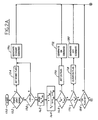
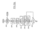
- Speed control system 10 is first described in general terms with reference to the block diagram shown in Figure 1. More detailed description is provided later herein with particular reference to Figures 2-12.
- Speed control system 10 controls the engine throttle (not shown) via cable drum 12, connected to throttle cable 14.
- speed control system 10 is responsive to: vehicle speed sensor 18 which is described in greater detail in U.S. Patent Application Serial No. 280,907, the specification of which is incorporated herein by reference; brake light switch 24; and brake dump switch 26 which is responsive to a predetermined hydraulic fluid pressure in the brake line such as, for example, 100 psi.
- the above inputs are filtered and buffered in a conventional manner by input signal conditioning circuitry 28.
- speed control system 10 is responsive to multiplex switch assembly 30 mounted on the vehicle steering wheel (not shown).
- multiplex switch assembly 30 includes the following operator actuable momentary switches: ON/OFF switch 32, COAST switch 34, SET/ACCEL switch 36, and RESUME/CANCEL switch 38.
- Microcomputer 42 a conventional microcomputer such as the 6805 series, is shown responsive to the above described inputs for controlling stepper motor 50 which in turn controls cable drum 12 via reduction gearing 54 and electromagnetic clutch 56.
- electromagnetic clutch 56 includes clutch plates 58a and 58b wherein clutch plate 58b is displaced against a return spring (not shown) in response to the flow of electrical current through coil 60.
- coil 60 is shown having one end connected to an electrical ground via clutch driver 64, a field effect transistor in this particular example, which is responsive to microcomputer 42.
- the other end of coil 60 is coupled to battery power V B via brake dump switch 26.
- microcomputer 42 instructs stepper motor 50 to turn to an idle position and thereafter opens electromagnetic clutch 56 via clutch driver 64.
- electromagnetic clutch 56 becomes immediately disengaged upon actuation of brake dump switch 26 when a predetermined pressure is achieved in the brake system.
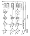
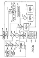
- multiplex switch assembly 30 receives electrical power (V B ') at node 64 via the relay coil of electrical horn assembly 66 through slip ring 70. Electrical ground is shown received at node 72 of multiplex switch assembly 30 via slip ring 74.
- Switch assembly 30 includes output node 80 which is coupled to node 82 of bridge circuit 86 via slip ring 88.
- a multiplexed output signal or voltage is provided at node 80 by multiplex switch assembly 30.
- Microcomputer 42 decodes the multiplexed output signal to provide the appropriate command signals. In this particular example, one of five preselected voltages is provided at node 82 (V82) by actuation of either momentary switch 32, 34, 36, or 38.
- ON/OFF switch 32 is shown as a single pole double throw momentary switch having its pole connected to node 80, its "ON" position connected to node 64, and its "OFF” position connected to electrical ground at node 72.
- COAST switch 34 is shown as a momentary switch connected in series with resistor 94 between node 80 and node 72.
- SET/ACCEL switch 36 is shown as a momentary switch connected in series with resistor 96 between node 80 and node 72.
- RESUME/CANCEL switch 38 is shown as a momentary switch connected in series with resistor 98 between node 80 and node 72.
- Horn switch 92 is connected in series between nodes 64 and 74.
- Electrical bridge 86 is shown including two resistive voltage dividers coupled between electrical ground and node 102 which in turn is coupled to V B .
- the first voltage divider includes resistor 114 (R114) coupled between node 102 and node 82, and resistor 116 (R116) coupled between electrical ground and node 82.
- the second resistive voltage divider includes resistor 120 (R120) and resistor 122 (R122) interconnected with node 104. Nodes 82 and 104 are shown connected to respective A/D inputs A/D1 and A/D2 of microcomputer 42.
- resistor 94 is coupled in parallel with resistor 116 of electrical bridge 86. Accordingly, the voltage at node 82 during depression of COAST switch 34 is represented by: V B *
- resistor 96 While SET/ACCEL switch 36 is held in the depressed position, resistor 96 is coupled in parallel with resistor 116. During such momentary depression, the voltage at node 82 is represented by: V B *
- the voltage at node 104 (V104) of bridge 86 is a system reference voltage determined by dividing V B by the second resistive voltage divider including resistors 120 and 122 (i.e., V B * R120/R120 + R122) . Any variation in battery voltage, voltage transients or noise on the voltage line will affect both V82 and V104 in a proportionate manner. As described below with reference to Figures 2A-2B, microcomputer 42 scales V82 by V104 to cancel the effects of voltage variations and noise from V82.
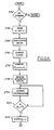
- microcomputer 42 in decoding multiplex switch assembly 30, and providing speed control commands is now described with reference to the flowchart shown in Figures 2A-2B.
- Each block shown is representative of process steps performed by microcomputer 42 during each of its background loops.
- the process shown may be performed by other components such as analog circuitry or discrete logic components commonly referred to as Integrated Circuits.
- step 152 the brake light signal is sampled in step 152.
- the Brake Flag is set and the STANDBY COMMAND generated (see steps 154 and 156).
- stepper motor 50 is phase stepped to an idle throttle position and electromagnetic clutch 56 then opened. Thereafter, resumption of speed control operation occurs with either a SET COMMAND or a RESUME COMMAND.
- step 158 compares actual vehicle speed (v) to preselected range ⁇ around reference speed ms which is stored in memory. When vehicle speed is beyond this preselected range, a STANDBY COMMAND is generated (steps 156 and 158). When vehicle speed is within the preselected range, the digital representation of V82 and V104 is sampled during step 162. Command signal V c is then generated in step 164 by scaling V82 with V104 to eliminate the effects of voltage variations and noise at node 82 as previously described herein. Accordingly, command signal V c is a digital representation or coding of V82 which in turn is a voltage representation of switch actuation in multiplex switch assembly 30.
- an ON Flag is set and the ON COMMAND generated when the digital representation of V82 is greater than V104. Stated another way, speed control operation is enabled when the above comparison indicates that ON/OFF Switch 32 is momentary actuated in the ON position.
- V c is then compared to a digital representation of the voltage, or voltage range, associated with momentary actuation of ON/OFF switch 32 in the OFF position (V OFF ) during step 176. If V c is equal to V OFF , the ON Flag is cleared and the OFF COMMAND generated during steps 178 and 180. Stepper motor 50 is then sequenced to an idle position and electromagnetic clutch assembly 56 opened. Speed control operation cannot thereafter be reactuated until an ON COMMAND is received.
- command signal V c is compared to signal V Set which is a digital representation of the voltage at node 82 during actuation of SET/ACCEL switch 36 (see step 186). If command signal V c and signal V Set are equal, the previous state of signal V c is then checked for an idle switch condition (V Idle ) corresponding to concurrent deactuation of all momentary switches in multiplex switch assembly 30 (see step 188). Should the previous state be other than an idle switch position, two switches may be concurrently actuated by the operator, in which case further speed control processing is exited.
- V Idle idle switch condition
- step 186 If command signal V c is equal to V Set (see step 186), and the previous state of command signal V c was at an idle position (see step 188) indicating that all switches were previously deactuated, then the Brake Flag is checked during step 190. It is noted that the Brake Flag is set during application of the vehicular brakes (see steps 150 and 152) and cleared when command signal V c is detected at an idle position indicating that all momentary switches were concurrently deactuated (see steps 230 and 232).
- command signal V c is checked to see if it was also at V Set during the previous background loop. If it was not, then a SET COMMAND is generated (see steps 192 and 194). On the other hand, if command signal V c was also at V Set during the previous background loop, an ACCEL COMMAND is generated (see steps 192 and 196). Stated another way, detection of continued depression of SET/ACCEL switch 36 results in an ACCEL COMMAND.
- the SET COMMAND begins initialising speed control operation to achieve the vehicle speed present at the time SET/ACCEL switch 36 is depressed. During continued depression of the switch, speed control system 10 accelerates the vehicle by incrementing the set speed in a preprogrammed manner.
- Decoding the actuation of COAST switch 34 occurs during process step 200.
- V Idle the digital representation of the voltage at node 82 associated with such actuation is detected
- V c the previous state of command signal V c is checked in step 202.
- a COAST COMMAND is generated. Otherwise, processing for the particular background loop ceases.
- stepper motor 50 is turned to idle. Release of COAST switch 34 results in reinitialising speed control operation at the vehicle speed which occurred at the time of such release.
- Decoding actuation of RESUME/CANCEL switch 38 and subsequent generation of the RESUME COMMAND begins with step 210.
- the previous state of command signal V c is checked for an idle condition during step 212. If all switches were previously deactuated and the Brake Flag is in the cleared state (see step 214), the Standby Mode is then checked during (see step 216). If previously in the Standby Mode, the RESUME COMMAND is then generated during step 218. However, if speed control was not previously in the Standby Mode (i.e., speed control in control mode), then depression of RESUME/CANCEL switch 38 is interpreted as a Cancel and the Standby Mode generated (step 220).
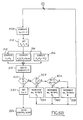
- step 240 speed error signal v e is computed in step 246 by subtracting actual vehicle speed v from reference speed ms which is stored in memory location m.
- Gain constants k p (proportional term), k q (quadratic term), and k I (integral term) are set in step 248 as a function of vehicle speed.
- each gain constant is one of three values each associated with one of three speed ranges. These speed ranges are designated as a high speed range (v h ), a medium speed range (v m ), and a low speed range (v l ).
- proportional, quadratic, and integral speed control are derived from error speed signal v e .
- the proportional speed control term is provided by multiplying proportional gain constant k p times speed error signal v e . This proportional term provides relatively fast speed control response to a speed error.
- the integral control term is computed in step 252 by integrating speed error signal v e , multiplying this integral by integral term k I , and adding an initial throttle position designated as TP i .
- the computation of initial throttle position TP i is described later herein with particular reference to Figure 6.
- This integral control term provides speed control system 10 with stable steady-state operation.
- the quadratic speed control term is calculated by multiplying quadratic constant k q times the product of error signal v e and the absolute value of error signal v e . This particular multiplication is used to advantage for generating a quadratic control term having the sign of error signal v e .
- the quadratic, integral, and proportional control terms are then added in step 258 to generate throttle position command signal TP. As described later herein with particular reference to Figure 5, throttle position command signal TP causes stepper motor 50 to turn to the commanded throttle position.
- is plotted as a function of speed error signal v e . It is noted that at low speed error signals (such as v e less than 1 mph), the quadratic control term is relatively small due to its squaring feature. On the other hand, the quadratic control term contributes substantially at higher speed error signals. To prevent excessive contribution at high speed error signals, the quadratic control term is clipped or limited at predetermine positive and negative limits.
- An advantage of the quadratic control term utilised herein is that small speed error signals are essentially ignored thereby providing a more stable speed control system. On the other hand, large corrections are quickly provided for significant speed errors thereby achieving a speed control system with a relatively fast response time.
- throttle position command TP is provided in a manner described later herein with particular reference to Figure 4.
- throttle position command TP is compared to total phase count ⁇ c which, as described below, infers the actual position of stepper motor 50 and accordingly the throttle plate (not shown).
- the difference between throttle position TP and phase count ⁇ c is representative of the angular position which stepper motor 50 must be incremented or decremented to in order to achieve the throttle position commanded by microcomputer 42.
- a sequence of phase pulses ( ⁇ 1, ⁇ 2, and ⁇ 3) is generated during step 276 for turning stepper motor 50 to throttle position TP.
- phase pulses ⁇ 1, ⁇ 2, and ⁇ 3 are generated for turning stepper motor 50 in discrete phase steps, each pulse is counted to provide a total phase count ⁇ c in step 278 which is related to the actual position of stepper motor 50.
- the above described process then continues the next background loop of microcomputer 42 when a new throttle position command is received.
- step 282 Upon recognition of the SET COMMAND in step 282, a rounded off value of actual vehicle speed at the time of actuation of SET/ACCEL switch 36 is stored as a set or desired speed in the rs memory location (see step 284). Stepper motor 50 is then zeroed or turned to an idle position and electromagnetic clutch assembly 56 engaged during steps 288 and 290.
- the integrator memory is initialised with initial throttle position TP i in step 294 a SET COMMAND (as described in greater detail later herein, a similar initialising process occurs after a RESUME COMMAND or ACCEL COMMAND).
- Stepper motor 50 is then advanced until its angular position, as represented by phase count ⁇ c , reaches initial throttle position TP i as shown by process steps 298 and 300.
- Actual vehicle speed existing at that time is then stored as initial reference speed ms i during process step 304.
- reference speed ms is incremented in a preprogrammed manner until desired speed rs is achieved.
- speed error signal v e is generated by subtracting actual vehicle speed (v) from reference speed ms as reference speed ms is being incremented (step 308).
- Proportional gain constant k p , quadratic gain constant k q , and integral gain constant k I are set in a manner described later herein with particular reference to Figures 15 and 16.
- throttle position (TP) is determined in the same manner as previously described herein with particular reference to process steps 250, 252, 254, and 258 shown in Figure 3.
- the programming for incrementing reference speed ms is provided in steps 322-334. In general, a preselected number of ramps are utilised dependent upon vehicle speed. If vehicle speed is less than initial reference speed ms i plus predetermined deviation ⁇ 1 (such as one mile per hour), then initial reference speed ms i is incremented at predetermined Rate 1.
- reference speed ms is incremented at predetermined Rate 2.
- reference speed ms is set equal to desired speed rs during step 330.
- ms is incremented at Rate 3 from ms i to rs for providing gradual vehicle acceleration to reference speed rs.
- the control mode is entered as indicated by process step 336 in Figure 6.
- speed control system 10 maintains vehicle speed at reference speed rs.
- speed control system 10 is initialised with an adaptively learned target throttle position such that desired speed rs is achieved in a stable manner with minimal undershoot, overshoot, or abrupt changes in vehicle speed.
- the adaptive learning process of target throttle positioning enables speed control system 10 to automatically adapt to different vehicles, and to variations among the same vehicle upon which it may be installed.
- step 382 stepper motor 50 is turned to an idle position (see step 384) and electromagnetic clutch assembly 56 activated (see step 388).
- initial throttle position TP i is computed by multiplying vehicle speed existing at the time resume switch 38 is depressed times slope value "a" and adding adaptively learned offset value c i .
- the integrator memory is then initialised with the computed initial target position TP i (see step 394).
- Stepper motor 50 is advanced until it reaches a phase count associated with target throttle position TP i (see steps 398 and 400).
- Actual vehicle speed v is then stored as reference speed ms i in step 404.
- step 408 speed error signal v e is computed by subtracting vehicle speed from reference speed ms.
- Proportional gain constant k p , quadratic gain constant k q , and integral gain constant k I are set in step 410.
- throttle position TP is determined in the same manner as previously described herein with particular reference to process steps 250, 252, 254, and 258 shown in Figure 3.
- FIG. 10A-10B Figures 11A-11C, and Figures 12A-12C.
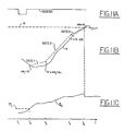
- Figures 11A-11D represent a hypothetical resume operation wherein reference speed ms is greater than actual vehicle speed v (i.e., v e > zero) throughout resume operations.
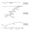
- Figures 12A-12C represent a more complex hypothetical resume operation wherein actual vehicle speed v exceeds reference speed ms (i.e., v e ⁇ zero) during a portion of resume operation.
- Resume speed control operation is first described of conditions when vehicle speed v is less than reference speed ms (i.e., v e > zero). After a determination is made that the speed error signal v e is positive (see step 430) and reference speed ms is less than set speed rs (see step 432), vehicle speed v is compared to various speed ranges (see steps 434, 436, and 438). More specifically, when vehicle speed v is less than predetermined value ⁇ 3 from set speed rs and within predetermined value ⁇ 1 from initial reference speed ms i , reference speed ms is incremented at predetermined rate R1 as shown by steps 434, 436, and 438.
- reference speed ms is incremented at rate R2 (see step 440). If vehicle speed v is greater than set speed rs minus ⁇ 3 (see step 434), reference speed ms is incremented at rate R3 (see step 442) until reference speed ms reaches set speed rs (see steps 432 and 446).
- reference speed ms is initialised with vehicle speed v when stepper motor 50 reaches target throttle position TP i at time t2.
- Initial reference speed ms i is then gradually advanced at rate R1 until vehicle speed v reaches initial reference speed ms i plus ⁇ 1 at time t3.
- reference speed ms is incremented at rate R2 until vehicle speed v reaches set speed rs minus ⁇ 3 at time t4.
- reference speed ms is incremented at rate R3 until it reaches set speed rs at time t5.
- Speed control operation when speed error signal v e is negative (i.e., v > ms) during a portion of resume operation is now described with continuing reference to Figures 10A-10B, and reference to the hypothetical example graphically shown in Figures 12A-12C.
- Vehicle speed is first compared to an upper reference speed ums (see step 460) which, in this particular example, is generated by adding a predetermined value ⁇ m to reference speed ms during each background loop of microcomputer 42.
- reference speed ms is incremented to upper reference speed ums as shown in steps 460 and 462.
- reference speed ms is updated with vehicle speed v (step 468).
- reference speed ms is incremented at rate R3 when vehicle speed is within a predetermined range ⁇ 3 of set speed rs.
- Resume switch 38 is shown actuated at time t1 in Figure 12A.
- stepper motor 50 is turned to target throttle position TP i .
- line 470 represents reference speed ms incremented at rates R1, R2, and R3 under hypothetical conditions where vehicle speed v is less than reference speed ms.
- line 472 represents upper reference speed ums which is incremented at rates R1, R2, and R3 under hypothetical conditions where vehicle speed v is less than upper reference speed ums.
- Line 474 represents actual vehicle speed v for the example presented herein.
- the solid portions of lines 470, 472, and 474 represent the actual reference speed ms utilised for speed error control in the particular example presented herein.
- reference speed ms is increased at rate R1 until it is greater than initial reference speed ms i plus ⁇ 1 as shown at time t3. Thereafter, reference speed ms is increased at rate R2. As shown in the previous example presented herein with reference to Figures 11A-11C, reference speed ms would increase at rate R2 until vehicle speed v reaches set speed rs minus ⁇ 3. However, as shown in the particular example presented in Figure 12B, vehicle speed v exceeds reference speed ms at time t4. Reference speed ms is therefore set to vehicle speed v at time t4.
- smooth resume operation is provided which adapts to actual vehicle speed under conditions of operator acceleration and downhill operation.
- unique manner of initialising the integrator with throttle position based upon vehicle speed v and reinitialising the integrator with target throttle position based upon set speed rs provides smooth and stable operation with minimal undershoot or overshoot.
Landscapes
- Engineering & Computer Science (AREA)
- Chemical & Material Sciences (AREA)
- Combustion & Propulsion (AREA)
- Transportation (AREA)
- Mechanical Engineering (AREA)
- Controls For Constant Speed Travelling (AREA)
- Electrical Control Of Air Or Fuel Supplied To Internal-Combustion Engine (AREA)
- Control Of Vehicle Engines Or Engines For Specific Uses (AREA)
Abstract
Claims (9)
- Système de commande de vitesse actionné par opérateur commandant le papillon du moteur afin de maintenir la vitesse du véhicule à une vitesse désirée, comprenant :
un moyen de commande comportant un asservissement couplé au papillon pour maintenir le papillon à une position désirée du papillon sur la base d'une position initiale du papillon et d'un écart entre la vitesse désirée et la vitesse du véhicule,
un moyen d'initiation pour produire ladite position initiale du papillon comme une fonction de la vitesse du véhicule existant lorsque l'actionnement par l'opérateur se produit, ladite position initiale du papillon étant produite par ledit moyen d'initiation en multipliant la vitesse du véhicule par une constante et en ajoutant un déplacement qui se rapporte à la position du papillon, au ralenti du moteur, et
un moyen d'apprentissage pour mettre à jour ladite position initiale du papillon en relation avec un écart par rapport à la position désirée du papillon à partir de ladite position initiale du papillon qui doit être utilisée comme ladite position initiale du papillon pendant un actionnement ultérieur par l'opérateur. - Système de commande de la vitesse selon la revendication 1, dans lequel ledit moyen de commande comporte un moyen pour intégrer ledit écart de vitesse.
- Système de commande de la vitesse couplé à un papillon du moteur pour obtenir et maintenir une vitesse désirée du véhicule comprenant :
un moyen d'ordre pour produire un ordre de position du papillon comportant un intégrateur pour intégrer un signal d'erreur de vitesse qui se rapporte à un écart de la vitesse actuelle du véhicule par rapport à la vitesse désirée,
un moyen d'initiation pour initialiser ledit intégrateur sur actionnement de l'opération de commande de la vitesse avec une position initiale du papillon qui se rapporte à la vitesse désirée existant au moment dudit actionnement,
un dispositif d'actionnement répondant audit intégrateur pour déplacer le papillon à ladite position initiale du papillon et par la suite ajuster le papillon en réponse audit ordre de position de papillon afin de maintenir la vitesse désirée, et
un moyen de mise à jour pour mettre à jour ladite position initiale du papillon afin d'initialiser ledit intégrateur pendant un actionnement ultérieur de ladite opération de commande de vitesse, ledit moyen de mise à jour comparant ladite position initiale du papillon produite pendant un actionnement précédent à une indication de la position réelle du papillon tandis que ledit moyen de commande maintient la vitesse désirée. - Système de commande de la vitesse selon la revendication 3, dans lequel ledit moyen d'initiation multiplie la vitesse du véhicule existant au moment de l'actionnement de la commande de la vitesse par une constante et ajoute une valeur de déplacement afin de calculer ladite position initiale du papillon.
- Système de commande de la vitesse selon la revendication 4, dans lequel ladite valeur de déplacement se rapporte à la position du papillon au ralenti du moteur.
- Système de commande de la vitesse selon la revendication 4, dans lequel ledit moyen de mise à jour met à jour ladite valeur de déplacement en soustrayant ledit produit de la vitesse du véhicule que multiplie ladite constante à partir de ladite indication de la position actuelle du papillon afin de produire une valeur de déplacement mise à jour.
- Procédé de commande de vitesse pour obtenir et maintenir une vitesse désirée du véhicule en commandant un papillon du moteur, comprenant les étapes consistant à : calculer une position initiale du papillon pour approcher la vitesse désirée sur actionnement de l'opération de commande de la vitesse en multipliant la vitesse désirée par une constante et en ajoutant un déplacement qui se rapporte à la fois au mou de la transmission du papillon et à la position du papillon au ralenti du moteur,
déplacer le papillon à ladite position initiale du papillon,
ajuster le papillon par rapport à un écart de la vitesse désirée par rapport à la vitesse du véhicule pour maintenir la vitesse désirée,
procurer l'indication de la position réelle du papillon tout en maintenant la vitesse désirée, et
mettre à jour ladite valeur de déplacement en soustrayant ledit produit de ladite constante que multiplie la vitesse du véhicule à partir de ladite position réelle du papillon afin de délivrer une valeur de déplacement mise à jour à ladite étape de calcul pendant un actionnement ultérieur de l'opération de commande de la vitesse. - Procédé de commande de la vitesse selon la revendication 7, dans lequel ledit moyen d'ajustement comporte l'intégration dudit écart.
- Procédé de commande de la vitesse selon la revendication 7, dans lequel ladite étape de procuration lie ladite intégrale afin de délivrer ladite indication de la position réelle du papillon.
Applications Claiming Priority (3)
| Application Number | Priority Date | Filing Date | Title |
|---|---|---|---|
| US743540 | 1991-08-09 | ||
| US07/743,540 US5333109A (en) | 1991-08-09 | 1991-08-09 | Vehicle speed control system with adaptive learning |
| PCT/EP1992/001729 WO1993002886A1 (fr) | 1991-08-09 | 1992-07-30 | Systeme a apprentissage adaptatif de regulation de la vitesse d'un vehicule |
Publications (2)
| Publication Number | Publication Date |
|---|---|
| EP0597944A1 EP0597944A1 (fr) | 1994-05-25 |
| EP0597944B1 true EP0597944B1 (fr) | 1995-08-09 |
Family
ID=24989182
Family Applications (1)
| Application Number | Title | Priority Date | Filing Date |
|---|---|---|---|
| EP92916573A Expired - Lifetime EP0597944B1 (fr) | 1991-08-09 | 1992-07-30 | Systeme a apprentissage adaptatif de regulation de la vitesse d'un vehicule |
Country Status (6)
| Country | Link |
|---|---|
| US (1) | US5333109A (fr) |
| EP (1) | EP0597944B1 (fr) |
| JP (1) | JPH06509761A (fr) |
| CA (1) | CA2114956C (fr) |
| DE (1) | DE69204069T2 (fr) |
| WO (1) | WO1993002886A1 (fr) |
Families Citing this family (14)
| Publication number | Priority date | Publication date | Assignee | Title |
|---|---|---|---|---|
| US5587908A (en) * | 1992-12-22 | 1996-12-24 | Mitsubishi Denki Kabushiki Kaisha | Distance measurement device and vehicle velocity control device for maintaining inter-vehicular distance |
| US6026784A (en) | 1998-03-30 | 2000-02-22 | Detroit Diesel Corporation | Method and system for engine control to provide driver reward of increased allowable speed |
| DE4341213C2 (de) * | 1993-12-03 | 1995-07-27 | Voith Turbo Kg | Steuerung zur Geschwindigkeitsbeeinflussung eines Fahrzeuges |
| US5479898A (en) * | 1994-07-05 | 1996-01-02 | Ford Motor Company | Method and apparatus for controlling engine torque |
| DE4443219C1 (de) * | 1994-12-05 | 1996-05-15 | Daimler Benz Ag | Tempomat-Fahrgeschwindigkeitsregeleinrichtung mit regelschwingungsbeeinflussenden Mitteln |
| US5801621A (en) * | 1995-07-17 | 1998-09-01 | Chrysler Corporation | Method for re-initializing vehicle parameters after a power loss in a motor vehicle |
| DE19627727B4 (de) * | 1996-07-10 | 2012-05-31 | Robert Bosch Gmbh | Verfahren und Vorrichtung zur Steuerung der Geschwindigkeit eines Fahrzeugs |
| US5835877A (en) * | 1996-11-25 | 1998-11-10 | General Motors Corporation | Automatic speed control with lash compensation |
| US5845619A (en) * | 1997-06-30 | 1998-12-08 | Reichlinger; Gary | Engine governor for repetitive load cycle applications |
| DE19924941A1 (de) | 1999-05-31 | 2000-12-21 | Daimler Chrysler Ag | Verfahren und Regelsystem zur Einstellung einer vorgebbaren Fahrzeug-Zielgeschwindigkeit |
| US6196188B1 (en) | 1999-07-15 | 2001-03-06 | Cummins Engine Co Inc | System and method for maintaining a constant throttle deadband |
| US6588400B2 (en) | 2001-05-14 | 2003-07-08 | Delphi Technologies, Inc. | Multi-strike throttle minimum learning system |
| JP3886909B2 (ja) * | 2003-01-08 | 2007-02-28 | 三菱電機株式会社 | 車両用走行速度制御装置 |
| DE102012209384A1 (de) * | 2012-06-04 | 2013-12-05 | Robert Bosch Gmbh | Verfahren und Vorrichtung zum Durchführen einer adaptiven Regelung einer Stellung eines Stellglieds eines Stellgebers |
Family Cites Families (9)
| Publication number | Priority date | Publication date | Assignee | Title |
|---|---|---|---|---|
| JPS59136533A (ja) * | 1983-01-27 | 1984-08-06 | Honda Motor Co Ltd | オートクルーズ制御装置 |
| JPS6071341A (ja) * | 1983-09-28 | 1985-04-23 | Nippon Denso Co Ltd | 定速走行装置 |
| JPS6317126A (ja) * | 1986-07-07 | 1988-01-25 | Nissan Motor Co Ltd | 車速制御装置 |
| JPH07108622B2 (ja) * | 1986-08-28 | 1995-11-22 | 日産自動車株式会社 | 車両用定速走行装置 |
| JPH0686187B2 (ja) * | 1987-01-28 | 1994-11-02 | トヨタ自動車株式会社 | 定速走行制御装置 |
| JPH0730728B2 (ja) * | 1987-05-30 | 1995-04-10 | マツダ株式会社 | エンジンのアイドル回転数制御装置 |
| JPH0741806B2 (ja) * | 1987-06-26 | 1995-05-10 | 三菱電機株式会社 | 車両用定速走行制御装置 |
| JPH01269617A (ja) * | 1988-04-20 | 1989-10-27 | Toyota Motor Corp | 車両用定速走行制御装置 |
| US5033431A (en) * | 1990-07-02 | 1991-07-23 | General Motors Corporation | Method of learning gain for throttle control motor |
-
1991
- 1991-08-09 US US07/743,540 patent/US5333109A/en not_active Expired - Fee Related
-
1992
- 1992-07-30 WO PCT/EP1992/001729 patent/WO1993002886A1/fr active IP Right Grant
- 1992-07-30 CA CA002114956A patent/CA2114956C/fr not_active Expired - Fee Related
- 1992-07-30 JP JP5503257A patent/JPH06509761A/ja active Pending
- 1992-07-30 EP EP92916573A patent/EP0597944B1/fr not_active Expired - Lifetime
- 1992-07-30 DE DE69204069T patent/DE69204069T2/de not_active Expired - Fee Related
Also Published As
| Publication number | Publication date |
|---|---|
| CA2114956A1 (fr) | 1993-02-18 |
| DE69204069T2 (de) | 1996-01-11 |
| DE69204069D1 (de) | 1995-09-14 |
| WO1993002886A1 (fr) | 1993-02-18 |
| EP0597944A1 (fr) | 1994-05-25 |
| JPH06509761A (ja) | 1994-11-02 |
| US5333109A (en) | 1994-07-26 |
| CA2114956C (fr) | 2001-06-05 |
Similar Documents
| Publication | Publication Date | Title |
|---|---|---|
| EP0597922B1 (fr) | Systeme de regulation de vitesse a gains variables associes aux erreurs de vitesse | |
| EP0597944B1 (fr) | Systeme a apprentissage adaptatif de regulation de la vitesse d'un vehicule | |
| US5177683A (en) | Speed control system with adaptive resume mode | |
| EP0425276B1 (fr) | Système de commande d'état de marche pour véhicule à moteur | |
| US5420793A (en) | Vehicle speed control system with quadratic feedback control | |
| EP0051002B1 (fr) | Système de commande automatique de vitesse de véhicule lourd | |
| US5634446A (en) | Cruise control based retarder control | |
| JPH0224689B2 (fr) | ||
| US4860210A (en) | Method of determining and using a filtered speed error in an integrated acceleration based electronic speed control system for vehicles | |
| EP0169693B1 (fr) | Systèmes de régulation automatique de vitesse | |
| US5260876A (en) | Speed control system with adaptive gain control during a speed alteration | |
| US4870584A (en) | System and method for automatically running a vehicle at a desired cruising speed | |
| EP1419924B1 (fr) | Système de commande de vitesse adaptatif | |
| US6317678B1 (en) | Method and control system for setting a presettable vehicle desired speed | |
| JPH022739B2 (fr) | ||
| US5177682A (en) | Speed control system with resume mode override | |
| US5552985A (en) | Cruising control apparatus | |
| US5390119A (en) | Vehicle speed control system with resume/cancel function | |
| US4553621A (en) | Automobile speed control system | |
| US5216609A (en) | Vehicle speed control system with multiplex switch decoding | |
| US4123116A (en) | Duty cycle translator with solenoid modeling circuit for adaptive braking system | |
| EP0661188A1 (fr) | Système pour contrôler automatiquement la vitesse d'un véhicule | |
| US4111497A (en) | Pressure command generator with initial condition logic for adaptive braking system | |
| US4905154A (en) | Method for compensating for cable length in a vehicle electronic speed control system | |
| US4556941A (en) | Transit vehicle speed maintaining control apparatus and method |
Legal Events
| Date | Code | Title | Description |
|---|---|---|---|
| PUAI | Public reference made under article 153(3) epc to a published international application that has entered the european phase |
Free format text: ORIGINAL CODE: 0009012 |
|
| 17P | Request for examination filed |
Effective date: 19940211 |
|
| AK | Designated contracting states |
Kind code of ref document: A1 Designated state(s): DE FR GB |
|
| 17Q | First examination report despatched |
Effective date: 19940912 |
|
| GRAA | (expected) grant |
Free format text: ORIGINAL CODE: 0009210 |
|
| AK | Designated contracting states |
Kind code of ref document: B1 Designated state(s): DE FR GB |
|
| REF | Corresponds to: |
Ref document number: 69204069 Country of ref document: DE Date of ref document: 19950914 |
|
| ET | Fr: translation filed | ||
| PLBE | No opposition filed within time limit |
Free format text: ORIGINAL CODE: 0009261 |
|
| STAA | Information on the status of an ep patent application or granted ep patent |
Free format text: STATUS: NO OPPOSITION FILED WITHIN TIME LIMIT |
|
| 26N | No opposition filed | ||
| REG | Reference to a national code |
Ref country code: FR Ref legal event code: TP Ref country code: FR Ref legal event code: CD |
|
| PGFP | Annual fee paid to national office [announced via postgrant information from national office to epo] |
Ref country code: GB Payment date: 20010622 Year of fee payment: 10 |
|
| PGFP | Annual fee paid to national office [announced via postgrant information from national office to epo] |
Ref country code: DE Payment date: 20010702 Year of fee payment: 10 |
|
| PGFP | Annual fee paid to national office [announced via postgrant information from national office to epo] |
Ref country code: FR Payment date: 20010709 Year of fee payment: 10 |
|
| REG | Reference to a national code |
Ref country code: GB Ref legal event code: 746 Effective date: 20010614 |
|
| REG | Reference to a national code |
Ref country code: FR Ref legal event code: D6 |
|
| REG | Reference to a national code |
Ref country code: GB Ref legal event code: IF02 |
|
| PG25 | Lapsed in a contracting state [announced via postgrant information from national office to epo] |
Ref country code: GB Free format text: LAPSE BECAUSE OF NON-PAYMENT OF DUE FEES Effective date: 20020730 |
|
| PG25 | Lapsed in a contracting state [announced via postgrant information from national office to epo] |
Ref country code: DE Free format text: LAPSE BECAUSE OF NON-PAYMENT OF DUE FEES Effective date: 20030201 |
|
| GBPC | Gb: european patent ceased through non-payment of renewal fee |
Effective date: 20020730 |
|
| PG25 | Lapsed in a contracting state [announced via postgrant information from national office to epo] |
Ref country code: FR Free format text: LAPSE BECAUSE OF NON-PAYMENT OF DUE FEES Effective date: 20030331 |
|
| REG | Reference to a national code |
Ref country code: FR Ref legal event code: ST |