EP0596766A1 - Entriegelbare Verbinderanordnung - Google Patents
Entriegelbare Verbinderanordnung Download PDFInfo
- Publication number
- EP0596766A1 EP0596766A1 EP93402538A EP93402538A EP0596766A1 EP 0596766 A1 EP0596766 A1 EP 0596766A1 EP 93402538 A EP93402538 A EP 93402538A EP 93402538 A EP93402538 A EP 93402538A EP 0596766 A1 EP0596766 A1 EP 0596766A1
- Authority
- EP
- European Patent Office
- Prior art keywords
- plug
- connection device
- locking
- ramp
- angle
- Prior art date
- Legal status (The legal status is an assumption and is not a legal conclusion. Google has not performed a legal analysis and makes no representation as to the accuracy of the status listed.)
- Withdrawn
Links
- 238000009434 installation Methods 0.000 description 3
- 230000005855 radiation Effects 0.000 description 3
- 210000002105 tongue Anatomy 0.000 description 3
- 230000000295 complement effect Effects 0.000 description 2
- 230000008878 coupling Effects 0.000 description 1
- 238000010168 coupling process Methods 0.000 description 1
- 238000005859 coupling reaction Methods 0.000 description 1
- 238000006073 displacement reaction Methods 0.000 description 1
- 230000000694 effects Effects 0.000 description 1
- 210000004907 gland Anatomy 0.000 description 1
- 238000005025 nuclear technology Methods 0.000 description 1
- 238000007789 sealing Methods 0.000 description 1
- 238000000926 separation method Methods 0.000 description 1
- 229910001220 stainless steel Inorganic materials 0.000 description 1
- 239000010935 stainless steel Substances 0.000 description 1
Images
Classifications
-
- H—ELECTRICITY
- H01—ELECTRIC ELEMENTS
- H01R—ELECTRICALLY-CONDUCTIVE CONNECTIONS; STRUCTURAL ASSOCIATIONS OF A PLURALITY OF MUTUALLY-INSULATED ELECTRICAL CONNECTING ELEMENTS; COUPLING DEVICES; CURRENT COLLECTORS
- H01R13/00—Details of coupling devices of the kinds covered by groups H01R12/70 or H01R24/00 - H01R33/00
- H01R13/62—Means for facilitating engagement or disengagement of coupling parts or for holding them in engagement
- H01R13/627—Snap or like fastening
- H01R13/6277—Snap or like fastening comprising annular latching means, e.g. ring snapping in an annular groove
Definitions
- the present invention relates to a connection device comprising a central insulating body having electrical contact elements, at least one fixed part relative to the insulating body and at least one locking element.
- the separation is carried out only by action on a key that includes the locking device and which is constituted by a sleeve adjusted on the socket of the plug and engaged over a portion of its length between the latter and the socket of the complementary plug.
- This portion has openings whose shape corresponds to that of the notches or lugs.
- the sleeve is capable of sliding axially so as to elastically flex the tongues towards the axis of the plug which releases the notches or lugs and unlocks the plug. The two parts of the plug can thus be easily separated.
- This locking device requires easy access to the plug for unlocking. Such access is not always possible in particular in the case of connectors which are used in nuclear technology and which allow a connection between a cold part, that is to say protected against radiation, and a hot part subjected to radiation, these two parts being separated by a wall whose thickness is generally greater than 1 meter.
- the present invention relates to a connection device allowing a plug to be uncoupled by traction on the cable which it equips.
- the invention relates to a connection device comprising a central insulating body having electrical contact elements, at least one piece fixed relative to the central insulating body, and at least one locking element, characterized in that said element Locking has a profiled region so as to allow unlocking of said locking element by applying to said part a tensile force greater than a given threshold, said part can in particular be a cable from a plug to be unlocked.
- the locking element is a locking pin carried by a plug which constitutes said connection device.
- the plug may include an external body, optionally displaceable by translation and having at least one opening, and said lug can be resiliently biased to pass through said opening.
- the two unlocking modes can be used, namely either by pulling on the plug in particular on its cable, or by axial displacement of the external body.
- the locking element is a locking stop carried by a base which constitutes said connection device.
- said profile is an inclined ramp so that the given threshold of force is between 5 and 30 daN.
- the angle of inclination of the ramp relative to the unlocking direction of the plug can be between 120 and 150 °.
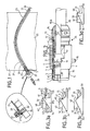
- FIG. 1 represents a configuration of wall crossing which can be implemented with a plug 25 according to the invention provided with one or more locking pins 5.
- the wall 22 to be traversed for example with a length of 1.5 meters, comprises an angled channel 23 which makes it possible to avoid a direct path of the radiation between the hot part located on the right in the drawing, and the cold part located on the left in the drawing.
- a base 27 is mounted in leaktight manner at the end of a thin tube, for example made of stainless steel referenced 21, which provides a wall covering for the bent channel 23.
- the base 26 has (see the detail in the box). enlarged from this part of FIG. 1) a flange 27 which is secured by screws to a flange 29 welded to the end of the tube 21.
- the double base 26 can receive a plug 28 of the conventional type mounted or disassembled manually in the cold part as well as a plug 25 having a cable 20 of great length and which is introduced into the tube 21.
- the problem posed relates to the unplugging of the sheet 25 due to the fact that it is not possible to disassemble the non-traversed base 26, except to interrupt the sealing between the "hot” part and the "cold” part of the installation.
- 2 shows the plug 25 according to the invention which allows easy disengaging by simple pulling on the rear part 24 of the cable 20 which protrudes from the tube 21 partly hot. This traction can be exerted by a remote handling device.
- the plug 25 comprises a plug body 1, the front part of which surrounds a sleeve 2 inside of which is housed an insulating body 3 having electrical contact elements 3 '. Outside the plug body 1 are housed in known manner locking tabs 8 of which the front end carries locking lugs 5.
- An O-ring 4 seals between the plug body and the insulating body 3.
- a sliding ring 6 having, in its front part, openings 45 surrounds the plug body and the locking tabs 8 and slides, at the front part, on these, and at the rear part on a flange 12 having a rear stop 12 '.
- the rear stop collar 12 is integral with a cable clamp 14 which is mounted from the rear inside the plug body 1 and which has a cable gland seal 11.
- the references 15, 16 and 17 denote flats allowing the remote manipulation by a remote manipulation clamp respectively of the cable clamp 14 forming the rear part of the plug, and of the axially translatable outer body 6.
- the reference 18 designates an angular polarizing pin mounted on the outer body 6, and 19 one of the two diametrically opposite pins allowing plugging in and out using a lever.
- the elements of FIG. 2 described above are part of the prior art and correspond to the locking multi-pin connectors of the "ULC" series sold by the Applicant.
- the plug according to the invention is distinguished by the design of the locking pin 5.
- a locking pin 30 according to the prior art has a front edge 34 and a sloping inclined profile. soft 32 allowing, by translation towards the rear of the outer body 6, to push the lug 30 inward. This release is effected by the fact the front edge 44 of the slot 45 rests on the inclined profile 32 and comes to release the rear edge 31 of the rear face 41 (locking stop) of the locking groove 40 of the base, has an external diameter 42 and a front edge 43.
- the edge rear 35 of the tongue 5 forms, with the elastic arms 33, an angle greater than 90 °, or 120 ° in Figure 3b, and 150 ° in Figure 3c.
- This inclination forms an inclined profile with a steep slope which allows the plug 25 to be disengaged by pulling on the cable 20 with a force greater than a given threshold.
- a disengaging force of between approximately 5 and 30 daN is obtained.
- the angle of 120 ° corresponds for example to tensile forces of the order of 10 to 30 daN and the angle of 150 ° to tensile forces between 5 and 15 daN depending on the case.
- the variation of the angle of inclination makes it possible to choose the disengaging force in a wide range. This is how this angle must be less than 90 ° if you prefer hanging, and more than 150 ° if you are looking for the least possible unlocking effort. This ensures that the locking of the plug by the rear edge of the lug 5 is normally ensured even in the event of vibrations.
- a pull on the cable 20 has the effect of overcoming the disengaging force of the lugs 5 as well as the disengaging force of the contact elements 3 '.
- the tensile force on the cable 20 is transmitted to the insulating body 3 and to the tongues 8 via the plug body 1.
- the sleeve 6 can be made fixed relative to the insulating body 3 or else removed.
- this embodiment is compatible with the implementation of a sleeve 6 either fixed or translatable as in the case of the prior art which allows the plug to be unlocked as desired by release pins 5 by translation of the sleeve 6 or by pulling on the cable 20. Therefore, the plug of Figure 2 can keep the elements such as the pins 18 and 19 and / or the translatable sleeve 6 in the event that such compatibility is desired.
- FIG. 3d represents a variant according to which the locking stop 46 of the groove 40 which is in mechanical contact with the edge 31 of a lug 30, is inclined in the direction of disengaging of the plug 25.
- the lug can be a lug 30 of the known prior art shown (therefore using a plug according to the prior art) or else a lug 5 having a profile 35 preferably parallel to the inclined edge 46.
- the profiles of the lug can be constituted by spherical sectors acting on profiles parallel to the inclined edges. This allows surface locking rather than linear.
- the device of the invention does not furthermore have the drawback of keeping the two parts of the plug firmly coupled even in the event that an incident occurs on the cable. Such incidents can occur inside a hot cell when the cable is hooked by a remote manipulator arm and where maintaining the connection risks causing damage to the cable and / or the remote manipulator.
- This same type of incident can occur for operators connected by a cable to a fixed frame to which they risk remaining connected in the event of sudden incidental movement.
- connection device therefore provides a safety "fuse” function reacting to any untimely pulling on the cable that it connects.
Landscapes
- Details Of Connecting Devices For Male And Female Coupling (AREA)
Applications Claiming Priority (2)
| Application Number | Priority Date | Filing Date | Title |
|---|---|---|---|
| FR9213226A FR2697685B1 (fr) | 1992-11-04 | 1992-11-04 | Dispositif de connexion déverrouillable. |
| FR9213226 | 1992-11-04 |
Publications (1)
| Publication Number | Publication Date |
|---|---|
| EP0596766A1 true EP0596766A1 (de) | 1994-05-11 |
Family
ID=9435181
Family Applications (1)
| Application Number | Title | Priority Date | Filing Date |
|---|---|---|---|
| EP93402538A Withdrawn EP0596766A1 (de) | 1992-11-04 | 1993-10-14 | Entriegelbare Verbinderanordnung |
Country Status (3)
| Country | Link |
|---|---|
| EP (1) | EP0596766A1 (de) |
| JP (1) | JPH06203915A (de) |
| FR (1) | FR2697685B1 (de) |
Cited By (3)
| Publication number | Priority date | Publication date | Assignee | Title |
|---|---|---|---|---|
| NL1017001C2 (nl) * | 2000-12-28 | 2002-07-01 | Fci S Hertogenbosch B V | Connector en kabel die deze omvat. |
| WO2011055125A1 (en) * | 2009-11-05 | 2011-05-12 | Ab Connectors Limited | Connector assembly and a connector part thereof |
| EP4350404A1 (de) * | 2022-10-05 | 2024-04-10 | Radiall | Elektrischer und/oder optischer kontakt mit einem körper und einer kabelmuffe zur vermeidung einer fehlentriegelung einer verbindung, verbinder oder adapter zur aufnahme eines solchen kontaktes |
Citations (4)
| Publication number | Priority date | Publication date | Assignee | Title |
|---|---|---|---|---|
| FR1201817A (fr) * | 1957-08-27 | 1960-01-06 | Fiche de contact électrique | |
| EP0187887A1 (de) * | 1985-01-18 | 1986-07-23 | Hosiden Electronics Co., Ltd. | Steckverbinder mit Verriegelungsmechanismus |
| DE8903055U1 (de) * | 1989-03-13 | 1989-05-03 | Franz Binder GmbH & Co Elektrische Bauelemente KG, 74172 Neckarsulm | Steckverbindungsleiste |
| FR2659502A1 (fr) * | 1990-03-06 | 1991-09-13 | Bernier Ets | Dispositif de raccordement a deboitement rapide. |
Family Cites Families (2)
| Publication number | Priority date | Publication date | Assignee | Title |
|---|---|---|---|---|
| JPS61296668A (ja) * | 1985-06-25 | 1986-12-27 | 松下電工株式会社 | テレホンジヤツク |
| NL9001952A (nl) * | 1990-09-05 | 1992-04-01 | Philips Nv | Verbindingsorgaan met kamer voor steker. |
-
1992
- 1992-11-04 FR FR9213226A patent/FR2697685B1/fr not_active Expired - Fee Related
-
1993
- 1993-10-14 EP EP93402538A patent/EP0596766A1/de not_active Withdrawn
- 1993-11-04 JP JP27575293A patent/JPH06203915A/ja active Pending
Patent Citations (5)
| Publication number | Priority date | Publication date | Assignee | Title |
|---|---|---|---|---|
| FR1201817A (fr) * | 1957-08-27 | 1960-01-06 | Fiche de contact électrique | |
| BE677833A (de) * | 1957-08-27 | 1966-08-01 | ||
| EP0187887A1 (de) * | 1985-01-18 | 1986-07-23 | Hosiden Electronics Co., Ltd. | Steckverbinder mit Verriegelungsmechanismus |
| DE8903055U1 (de) * | 1989-03-13 | 1989-05-03 | Franz Binder GmbH & Co Elektrische Bauelemente KG, 74172 Neckarsulm | Steckverbindungsleiste |
| FR2659502A1 (fr) * | 1990-03-06 | 1991-09-13 | Bernier Ets | Dispositif de raccordement a deboitement rapide. |
Cited By (5)
| Publication number | Priority date | Publication date | Assignee | Title |
|---|---|---|---|---|
| NL1017001C2 (nl) * | 2000-12-28 | 2002-07-01 | Fci S Hertogenbosch B V | Connector en kabel die deze omvat. |
| EP1220370A1 (de) * | 2000-12-28 | 2002-07-03 | Fci | Verbinder und Kabel mit diesem Verbinder |
| WO2011055125A1 (en) * | 2009-11-05 | 2011-05-12 | Ab Connectors Limited | Connector assembly and a connector part thereof |
| EP4350404A1 (de) * | 2022-10-05 | 2024-04-10 | Radiall | Elektrischer und/oder optischer kontakt mit einem körper und einer kabelmuffe zur vermeidung einer fehlentriegelung einer verbindung, verbinder oder adapter zur aufnahme eines solchen kontaktes |
| FR3140714A1 (fr) * | 2022-10-05 | 2024-04-12 | Radiall | Contact électrique et/ou optique comprenant un corps et un manchon de câble configuré pour éviter un déverrouillage intempestif de connexion, connecteur ou adaptateur logeant un tel contact. |
Also Published As
| Publication number | Publication date |
|---|---|
| JPH06203915A (ja) | 1994-07-22 |
| FR2697685B1 (fr) | 1994-12-23 |
| FR2697685A1 (fr) | 1994-05-06 |
Similar Documents
| Publication | Publication Date | Title |
|---|---|---|
| EP0723103B1 (de) | Vorrichtung zum schnellen Verbinden eines Rohres mit einem starren Element | |
| EP0960300B1 (de) | Vorrichtung zum schnellen verbinden eines rohres mit einem starren element mit trennsicherungsring und zustandsanzeiger | |
| CA2754552C (fr) | Dispositif de raccord avec verrouillage par griffes filetees et raccord comprenant un tel dispositif | |
| WO1996017201A1 (fr) | Dispositif de raccordement rapide d'un tube a un embout rigide | |
| FR2757317A1 (fr) | Fiche de raccord electrique et raccord electrique a enfichage | |
| FR2733365A1 (fr) | Assemblage de connecteur electrique a levier d'accouplement pivotant | |
| EP0663706A1 (de) | Mikrominiatur-Koaxialverbinder mit Schnappbefestigung | |
| EP0023189A1 (de) | Schnellkupplungsvorrichtungen zum Verbinden von Rohrleitungen | |
| EP0896182A1 (de) | Steckverbindungssystem | |
| FR2607573A1 (fr) | Perfectionnement aux dispositifs de raccordement rapide pour tubes souples, semi-rigides ou rigides | |
| EP0989348B1 (de) | Vorrichtung zum Schnellverbinden von Rohren | |
| EP1198684B1 (de) | Schutzkappe für ein rohrende | |
| EP0596766A1 (de) | Entriegelbare Verbinderanordnung | |
| EP2101097B1 (de) | Anschlussvorrichtung für den Transfer eines Fluids, Kreislauf, der diese Vorrichtung umfasst, und entsprechendes Montage-/Demontageverfahren | |
| CH472623A (fr) | Dispositif de raccordement de canalisations | |
| EP1067324B1 (de) | Schnellkupplung für Verbundrohr mit metallischem Kern | |
| EP1020677A1 (de) | Verbinderanordnung | |
| FR2527015A1 (fr) | Connecteur verrouillable et deverrouillable pour cables electriques | |
| BE1006139A3 (fr) | Desengagement automatique de fiches electriques. | |
| FR2735844A1 (fr) | Dispositif de raccordement rapide d'un tube a un element rigide | |
| EP0364380A1 (de) | Anschlusssystem, insbesondere für unter hohem Druck stehende hydraulische Leitung | |
| WO2010055222A1 (fr) | Dispositif de raccordement ayant des zones inversees d'etancheite et d'accrochage | |
| EP2204600A1 (de) | Gasanschluss für die Verbindung zwischen einem Festnetz zur Versorgung von gasförmigem Fluid und einem Gerät, das mit dem gasförmigen Fluid versorgt wird | |
| EP0599673A1 (de) | Verbinderhülse für abgedichtete Durchführung und dazugehörige Anordnung | |
| CA1092621A (fr) | Raccord entre conduites plastique et metallique pour traversee de facade d'un abonne au gaz |
Legal Events
| Date | Code | Title | Description |
|---|---|---|---|
| PUAI | Public reference made under article 153(3) epc to a published international application that has entered the european phase |
Free format text: ORIGINAL CODE: 0009012 |
|
| AK | Designated contracting states |
Kind code of ref document: A1 Designated state(s): AT BE CH DE ES IT LI |
|
| 17P | Request for examination filed |
Effective date: 19940620 |
|
| 17Q | First examination report despatched |
Effective date: 19950607 |
|
| STAA | Information on the status of an ep patent application or granted ep patent |
Free format text: STATUS: THE APPLICATION IS DEEMED TO BE WITHDRAWN |
|
| 18D | Application deemed to be withdrawn |
Effective date: 19951018 |