EP0596766A1 - Releasable connector device - Google Patents
Releasable connector device Download PDFInfo
- Publication number
- EP0596766A1 EP0596766A1 EP93402538A EP93402538A EP0596766A1 EP 0596766 A1 EP0596766 A1 EP 0596766A1 EP 93402538 A EP93402538 A EP 93402538A EP 93402538 A EP93402538 A EP 93402538A EP 0596766 A1 EP0596766 A1 EP 0596766A1
- Authority
- EP
- European Patent Office
- Prior art keywords
- plug
- connection device
- locking
- ramp
- angle
- Prior art date
- Legal status (The legal status is an assumption and is not a legal conclusion. Google has not performed a legal analysis and makes no representation as to the accuracy of the status listed.)
- Withdrawn
Links
Images
Classifications
-
- H—ELECTRICITY
- H01—ELECTRIC ELEMENTS
- H01R—ELECTRICALLY-CONDUCTIVE CONNECTIONS; STRUCTURAL ASSOCIATIONS OF A PLURALITY OF MUTUALLY-INSULATED ELECTRICAL CONNECTING ELEMENTS; COUPLING DEVICES; CURRENT COLLECTORS
- H01R13/00—Details of coupling devices of the kinds covered by groups H01R12/70 or H01R24/00 - H01R33/00
- H01R13/62—Means for facilitating engagement or disengagement of coupling parts or for holding them in engagement
- H01R13/627—Snap or like fastening
- H01R13/6277—Snap or like fastening comprising annular latching means, e.g. ring snapping in an annular groove
Definitions
- the present invention relates to a connection device comprising a central insulating body having electrical contact elements, at least one fixed part relative to the insulating body and at least one locking element.
- the separation is carried out only by action on a key that includes the locking device and which is constituted by a sleeve adjusted on the socket of the plug and engaged over a portion of its length between the latter and the socket of the complementary plug.
- This portion has openings whose shape corresponds to that of the notches or lugs.
- the sleeve is capable of sliding axially so as to elastically flex the tongues towards the axis of the plug which releases the notches or lugs and unlocks the plug. The two parts of the plug can thus be easily separated.
- This locking device requires easy access to the plug for unlocking. Such access is not always possible in particular in the case of connectors which are used in nuclear technology and which allow a connection between a cold part, that is to say protected against radiation, and a hot part subjected to radiation, these two parts being separated by a wall whose thickness is generally greater than 1 meter.
- the present invention relates to a connection device allowing a plug to be uncoupled by traction on the cable which it equips.
- the invention relates to a connection device comprising a central insulating body having electrical contact elements, at least one piece fixed relative to the central insulating body, and at least one locking element, characterized in that said element Locking has a profiled region so as to allow unlocking of said locking element by applying to said part a tensile force greater than a given threshold, said part can in particular be a cable from a plug to be unlocked.
- the locking element is a locking pin carried by a plug which constitutes said connection device.
- the plug may include an external body, optionally displaceable by translation and having at least one opening, and said lug can be resiliently biased to pass through said opening.
- the two unlocking modes can be used, namely either by pulling on the plug in particular on its cable, or by axial displacement of the external body.
- the locking element is a locking stop carried by a base which constitutes said connection device.
- said profile is an inclined ramp so that the given threshold of force is between 5 and 30 daN.
- the angle of inclination of the ramp relative to the unlocking direction of the plug can be between 120 and 150 °.
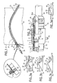
- FIG. 1 represents a configuration of wall crossing which can be implemented with a plug 25 according to the invention provided with one or more locking pins 5.
- the wall 22 to be traversed for example with a length of 1.5 meters, comprises an angled channel 23 which makes it possible to avoid a direct path of the radiation between the hot part located on the right in the drawing, and the cold part located on the left in the drawing.
- a base 27 is mounted in leaktight manner at the end of a thin tube, for example made of stainless steel referenced 21, which provides a wall covering for the bent channel 23.
- the base 26 has (see the detail in the box). enlarged from this part of FIG. 1) a flange 27 which is secured by screws to a flange 29 welded to the end of the tube 21.
- the double base 26 can receive a plug 28 of the conventional type mounted or disassembled manually in the cold part as well as a plug 25 having a cable 20 of great length and which is introduced into the tube 21.
- the problem posed relates to the unplugging of the sheet 25 due to the fact that it is not possible to disassemble the non-traversed base 26, except to interrupt the sealing between the "hot” part and the "cold” part of the installation.
- 2 shows the plug 25 according to the invention which allows easy disengaging by simple pulling on the rear part 24 of the cable 20 which protrudes from the tube 21 partly hot. This traction can be exerted by a remote handling device.
- the plug 25 comprises a plug body 1, the front part of which surrounds a sleeve 2 inside of which is housed an insulating body 3 having electrical contact elements 3 '. Outside the plug body 1 are housed in known manner locking tabs 8 of which the front end carries locking lugs 5.
- An O-ring 4 seals between the plug body and the insulating body 3.
- a sliding ring 6 having, in its front part, openings 45 surrounds the plug body and the locking tabs 8 and slides, at the front part, on these, and at the rear part on a flange 12 having a rear stop 12 '.
- the rear stop collar 12 is integral with a cable clamp 14 which is mounted from the rear inside the plug body 1 and which has a cable gland seal 11.
- the references 15, 16 and 17 denote flats allowing the remote manipulation by a remote manipulation clamp respectively of the cable clamp 14 forming the rear part of the plug, and of the axially translatable outer body 6.
- the reference 18 designates an angular polarizing pin mounted on the outer body 6, and 19 one of the two diametrically opposite pins allowing plugging in and out using a lever.
- the elements of FIG. 2 described above are part of the prior art and correspond to the locking multi-pin connectors of the "ULC" series sold by the Applicant.
- the plug according to the invention is distinguished by the design of the locking pin 5.
- a locking pin 30 according to the prior art has a front edge 34 and a sloping inclined profile. soft 32 allowing, by translation towards the rear of the outer body 6, to push the lug 30 inward. This release is effected by the fact the front edge 44 of the slot 45 rests on the inclined profile 32 and comes to release the rear edge 31 of the rear face 41 (locking stop) of the locking groove 40 of the base, has an external diameter 42 and a front edge 43.
- the edge rear 35 of the tongue 5 forms, with the elastic arms 33, an angle greater than 90 °, or 120 ° in Figure 3b, and 150 ° in Figure 3c.
- This inclination forms an inclined profile with a steep slope which allows the plug 25 to be disengaged by pulling on the cable 20 with a force greater than a given threshold.
- a disengaging force of between approximately 5 and 30 daN is obtained.
- the angle of 120 ° corresponds for example to tensile forces of the order of 10 to 30 daN and the angle of 150 ° to tensile forces between 5 and 15 daN depending on the case.
- the variation of the angle of inclination makes it possible to choose the disengaging force in a wide range. This is how this angle must be less than 90 ° if you prefer hanging, and more than 150 ° if you are looking for the least possible unlocking effort. This ensures that the locking of the plug by the rear edge of the lug 5 is normally ensured even in the event of vibrations.
- a pull on the cable 20 has the effect of overcoming the disengaging force of the lugs 5 as well as the disengaging force of the contact elements 3 '.
- the tensile force on the cable 20 is transmitted to the insulating body 3 and to the tongues 8 via the plug body 1.
- the sleeve 6 can be made fixed relative to the insulating body 3 or else removed.
- this embodiment is compatible with the implementation of a sleeve 6 either fixed or translatable as in the case of the prior art which allows the plug to be unlocked as desired by release pins 5 by translation of the sleeve 6 or by pulling on the cable 20. Therefore, the plug of Figure 2 can keep the elements such as the pins 18 and 19 and / or the translatable sleeve 6 in the event that such compatibility is desired.
- FIG. 3d represents a variant according to which the locking stop 46 of the groove 40 which is in mechanical contact with the edge 31 of a lug 30, is inclined in the direction of disengaging of the plug 25.
- the lug can be a lug 30 of the known prior art shown (therefore using a plug according to the prior art) or else a lug 5 having a profile 35 preferably parallel to the inclined edge 46.
- the profiles of the lug can be constituted by spherical sectors acting on profiles parallel to the inclined edges. This allows surface locking rather than linear.
- the device of the invention does not furthermore have the drawback of keeping the two parts of the plug firmly coupled even in the event that an incident occurs on the cable. Such incidents can occur inside a hot cell when the cable is hooked by a remote manipulator arm and where maintaining the connection risks causing damage to the cable and / or the remote manipulator.
- This same type of incident can occur for operators connected by a cable to a fixed frame to which they risk remaining connected in the event of sudden incidental movement.
- connection device therefore provides a safety "fuse” function reacting to any untimely pulling on the cable that it connects.
Abstract
Description
La présente invention a pour objet un dispositif de connexion comprenant un corps central isolant présentant des éléments de contact électrique, au moins une pièce fixe par rapport au corps isolant et au moins un élément de verrouillage.The present invention relates to a connection device comprising a central insulating body having electrical contact elements, at least one fixed part relative to the insulating body and at least one locking element.
On connaît de l'art antérieur, en particulier du brevet français 1 201 817, une fiche dont l'accouplement avec une fiche complémentaire ou avec une embase est réalisé par un dispositif comprenant d'une part deux crans d'arrêt ou ergots que forment les extrémités de deux languettes élastiques longitudinales découpées dans une douille et d'autre part, une gorge annulaire de verrouillage pratiquée dans une surface intérieure d'une douille de la fiche complémentaire ou de l'embase. Pour solidariser les deux parties de la fiche, il suffit d'introduire axialement les douilles l'une dans l'autre jusqu'à ce que les crans ou ergots s'engagent élastiquement dans la gorge annulaire. Quand la fiche est verrouillée, c'est-à-dire quand les deux parties mâle et femelle sont solidarisées, il est impossible de séparer les deux extrémités des fils raccordés en exerçant une traction sur ces derniers. La séparation est opérée uniquement par action sur une clé que comprend le dispositif de verrouillage et qui est constituée par un manchon ajusté sur la douille de la fiche et engagé sur une portion de sa longueur entre cette dernière et la douille de la fiche complémentaire. Cette portion présente des ouvertures dont la forme correspond à celle des crans ou ergots. Le manchon est susceptible de coulisser axialement de manière à faire fléchir élastiquement les languettes vers l'axe de la fiche qui dégage les crans ou ergots et déverrouille la fiche. Les deux parties de la fiche peuvent être ainsi facilement séparées.There is known from the prior art, in particular from French patent 1,201,817, a plug the coupling of which with an additional plug or with a base is produced by a device comprising on the one hand two notches or lugs which form the ends of two longitudinal elastic tabs cut from a socket and on the other hand, an annular locking groove made in an inner surface of a socket of the complementary plug or of the base. To secure the two parts of the plug, it suffices to introduce the bushes axially into one another until the notches or lugs engage elastically in the annular groove. When the plug is locked, that is to say when the two male and female parts are secured, it is impossible to separate the two ends of the connected wires by exerting traction on the latter. The separation is carried out only by action on a key that includes the locking device and which is constituted by a sleeve adjusted on the socket of the plug and engaged over a portion of its length between the latter and the socket of the complementary plug. This portion has openings whose shape corresponds to that of the notches or lugs. The sleeve is capable of sliding axially so as to elastically flex the tongues towards the axis of the plug which releases the notches or lugs and unlocks the plug. The two parts of the plug can thus be easily separated.
Ce dispositif de verrouillage impose un accès facile à la fiche en vue de son déverrouillage. Un tel accès n'est pas toujours possible en particulier dans le cas des connecteurs qui sont utilisés en technique nucléaire et qui permettent une connexion entre une partie froide, c'est-à-dire protégée contre les radiations, et une partie chaude soumise à des radiations, ces deux parties étant séparées par un mur dont l'épaisseur est généralement supérieure à 1 mètre.This locking device requires easy access to the plug for unlocking. Such access is not always possible in particular in the case of connectors which are used in nuclear technology and which allow a connection between a cold part, that is to say protected against radiation, and a hot part subjected to radiation, these two parts being separated by a wall whose thickness is generally greater than 1 meter.
La présente invention a pour objet un dispositif de connexion permettant à une fiche d'être désaccouplée par traction sur le câble qu'elle équipe.The present invention relates to a connection device allowing a plug to be uncoupled by traction on the cable which it equips.
Dans ce but l'invention concerne un dispositif de connexion comprenant un corps central isolant présentant des éléments de contact électrique, au moins une pièce fixe par rapport au corps central isolant, et au moins un élément de verrouillage, caractérisé en ce que ledit élément de verrouillage présente une région profilée de manière à permettre un déverrouillage dudit élément de verrouillage en appliquant à une dite pièce une force, de traction supérieure à un seuil donné, ladite pièce peut être en particulier un câble d'une fiche à déverrouiller.For this purpose, the invention relates to a connection device comprising a central insulating body having electrical contact elements, at least one piece fixed relative to the central insulating body, and at least one locking element, characterized in that said element Locking has a profiled region so as to allow unlocking of said locking element by applying to said part a tensile force greater than a given threshold, said part can in particular be a cable from a plug to be unlocked.
Selon une première variante de réalisation, l'élément de verrouillage est un ergot de verrouillage porté par une fiche qui constitue ledit dispositif de connexion.According to a first alternative embodiment, the locking element is a locking pin carried by a plug which constitutes said connection device.
La fiche peut comporter un corps extérieur, éventuellement déplaçable par translation et présentant au moins une ouverture et ledit ergot peut être rappelé élastiquement pour traverser ladite ouverture. Dans le cas où le corps extérieur est translatable axialement, les deux modes de déverrouillage peuvent être utilisés, à savoir soit par traction sur la fiche en particulier sur son câble, et soit par déplacement axial du corps extérieur.The plug may include an external body, optionally displaceable by translation and having at least one opening, and said lug can be resiliently biased to pass through said opening. In the case where the outer body is axially translatable, the two unlocking modes can be used, namely either by pulling on the plug in particular on its cable, or by axial displacement of the external body.
Selon une deuxième variante, l'élément de verrouillage est une butée de verrouillage portée par une embase qui constitue ledit dispositif de connexion.According to a second variant, the locking element is a locking stop carried by a base which constitutes said connection device.
Selon un mode de réalisation préféré de l'invention, ledit profil est une rampe inclinée de manière que le seuil donné de force soit compris entre 5 et 30 daN. L'angle d'inclinaison de la rampe par rapport à la direction de déverrouillage de la fiche peut être compris entre 120 et 150°.According to a preferred embodiment of the invention, said profile is an inclined ramp so that the given threshold of force is between 5 and 30 daN. The angle of inclination of the ramp relative to the unlocking direction of the plug can be between 120 and 150 °.
Les avantages et caractéristiques de l'invention apparaîtront mieux à la lecture de la description qui va suivre, donnée à titre d'exemple non limitatif, en liaison avec les dessins qui représentent :
- la figure 1, un ensemble de connexion à fiche et embase pour réaliser une traversée de paroi entre une partie "froide" et une partie "chaude" d'une installation nucléaire,
- la figure 2, une vue en coupe longitudinale partielle d'une fiche selon un mode de réalisation de l'invention,
- la figure 3a, un détail en coupe longitudinale d'une fiche selon l'antérieur précité,
- les figures 3b et 3c, deux exemples d'une fiche comprenant des profils selon un mode de réalisation préféré de l'invention, et
- la figure 3d, une coupe partielle d'une embase présentant une butée de verrouillage profilée selon l'invention.
- FIG. 1, a plug and socket connection assembly for making a wall crossing between a "cold" part and a "hot" part of a nuclear installation,
- FIG. 2, a view in partial longitudinal section of a plug according to an embodiment of the invention,
- FIG. 3a, a detail in longitudinal section of a plug according to the aforementioned anterior,
- FIGS. 3b and 3c, two examples of a sheet comprising profiles according to a preferred embodiment of the invention, and
- Figure 3d, a partial section of a base having a profiled locking stop according to the invention.
La figure 1 représente une configuration de traversée de paroi qui peut être mise en oeuvre avec une fiche 25 selon l'invention pourvue d'un ou plusieurs ergots de verrouillage 5. La paroi 22 à traverser, par exemple d'une longueur de 1,5 mètre, comporte un canal coudé 23 qui permet d'éviter un trajet direct des radiations entre la partie chaude située à droite sur le dessin, et la partie froide située à gauche sur le dessin. Une embase 27 est montée de manière étanche à l'extrémité d'un tube mince par exemple en acier inoxydable référencé 21, qui assure un revêtement de paroi du canal coudé 23. En particulier, l'embase 26 présente (voir en encadré le détail agrandi de cette partie de la figure 1) une collerette 27 qui est solidarisée par des vis à une collerette 29 soudée à l'extrémité du tube 21. La collerette 27, qui est montée sur l'embase par un écrou 26', comporte des joints toriques 27' permettant d'assurer l'étanchéité de la traversée. L'embase double 26 peut recevoir une fiche 28 de type classique montée ou démontée manuellement en partie froide ainsi qu'une fiche 25 présentant un câble 20 de grande longueur et qui est introduite dans le tube 21. Le problème posé vise le désenfichage de la fiche 25 en raison du fait qu'il n'est pas possible de démonter l'embase non traversée 26, sauf à interrompre l'étanchéité entre la partie "chaude" et la partie "froide" de l'installation. La figure 2 représente la fiche 25 selon l'invention qui permet un désenfichage facile par simple traction sur la partie arrière 24 du câble 20 qui dépasse du tube 21 en partie chaude. Cette traction peut être exercée par un appareillage de télémanipulation.FIG. 1 represents a configuration of wall crossing which can be implemented with a
Selon la figure 2, la fiche 25 comporte un corps de fiche 1 dont la partie avant entoure un manchon 2 à l'intérieur duquel est logé un corps isolant 3 présentant des éléments de contact électrique 3'. A l'extérieur du corps de fiche 1 sont logées de manière connue des languettes de verrouillage 8 dont l'extrémité avant porte des ergots de verrouillage 5. Un joint torique 4 assure l'étanchéité entre le corps de fiche et le corps isolant 3. Une bague coulissante 6 présentant, dans sa partie avant, des ouvertures 45 entoure le corps de fiche et les languettes de verrouillage 8 et coulisse, en partie avant, sur celles-ci, et en partie arrière sur une collerette 12 présentant une butée arrière 12'. La collerette de butée arrière 12 est solidaire d'un serre-câble 14 qui est monté par l'arrière à l'intérieur du corps de fiche 1 et qui présente un joint de presse-étoupe 11. Les repères 15, 16 et 17 désignent des méplats permettant la télémanipulation par une pince de télémanipulation respectivement du serre-câble 14 formant la partie arrière de la fiche, et du corps extérieur translatable axialement 6. Le repère 18 désigne un pion de détrompage angulaire monté sur le corps extérieur 6, et 19 l'un des deux pions diamétralement opposés permettant un enfichage et un désenfichage par levier. Les éléments de la figure 2 décrits ci-dessus font partie de l'art antérieur et correspondent aux connecteurs multibroches à verrouillage de la série "ULC" commercialisés par la Demanderesse.According to FIG. 2, the
La fiche selon l'invention se distingue par la conception de l'ergot de verrouillage 5. En effet, comme représenté à la figure 3a, un ergot de verrouillage 30 selon l'art antérieur présente un bord avant 34 et un profilé incliné en pente douce 32 permettant, par translation vers l'arrière du corps extérieur 6, de repousser vers l'intérieur l'ergot 30. Ce dégagement est opéré par le fait le bord avant 44 de la fente 45 appui sur le profil incliné 32 et vient dégager le bord arrière 31 de la face arrière 41 (butée de verrouillage) de la rainure de verrouillage 40 de l'embase, présente un diamètre externe 42 et un bord avant 43. En figures 3b, 3c, par contre, le bord arrière 35 de la languette 5 forme, avec les bras élastiques 33, un angle supérieur à 90°, soit de 120° à la figure 3b, et de 150° à la figure 3c. Cette inclinaison forme profil incliné à pente raide qui permet le désenfichage de la fiche 25 par traction sur le câble 20 avec une force supérieure à un seuil donné. En particulier, avec un angle compris entre 120 et 150° on obtient une force de désenfichage comprise entre environ 5 et 30 daN. L'angle de 120° correspond par exemple à des forces de traction de l'ordre de 10 à 30 daN et l'angle de 150° à des forces de traction entre 5 et 15 daN selon les cas d'espèce. La variation de l'angle d'inclinaison permet de choisir la force de désenfichage dans une large gamme. C'est ainsi que cet angle doit être inférieur à 90° si l'on privilégie l'accrochage, et supérieur à 150° si l'on recherche un effort de déverrouillage le plus faible possible. Ceci permet d'assurer que le verrouillage de la fiche par le bord arrière de l'ergot 5 est assuré normalement même en cas de vibrations. Pour déverrouiller le fiche, une traction sur le câble 20 a pour effet de vaincre la force de désenfichage des ergots 5 ainsi que la force de désenfichage des éléments de contact 3'. La force de traction sur le câble 20 est transmise au corps isolant 3 et aux languettes 8 par l'intermédiaire du corps de fiche 1. On remarquera également que le manchon 6 peut être rendu fixe par rapport au corps isolant 3 ou bien être supprimé.The plug according to the invention is distinguished by the design of the
Comme le montre la figure 2, ce mode de réalisation est compatible avec la mise en oeuvre d'un manchon 6 soit fixe, soit translatable comme dans le cas de l'art antérieur qui permet à la fiche de pouvoir être déverrouillée au choix par désencliquetage des ergots 5 par translation du manchon 6 ou par traction sur le câble 20. De ce fait, la fiche de la figure 2 peut conserver les éléments tels que les pions 18 et 19 et/ou le manchon translatable 6 dans le cas où une telle compatibilité est souhaitée.As shown in Figure 2, this embodiment is compatible with the implementation of a
La figure 3d représente une variante selon laquelle la butée de verrouillage 46 de la rainure 40 qui est en contact mécaniquement avec le bord 31 d'un ergot 30, est incliné dans la direction de désenfichage de la fiche 25. Dans ce cas, l'ergot peut être un ergot 30 de l'art antérieur connu représenté (donc en utilisant une fiche selon l'art antérieur) ou bien un ergot 5 ayant un profil 35 de préférence parallèle au bord incliné 46. Les profils de l'ergot peuvent être constitués par des secteurs sphériques agissant sur des profils parallèles aux bords inclinés. Ceci permet un verrouillage surfacique plutôt que linéaire.FIG. 3d represents a variant according to which the locking
Le dispositif de l'invention ne comporte pas par ailleurs l'inconvénient de maintenir fermement accouplées les deux parties de la fiche même dans le cas où un incident intervient sur le câble. De tels incidents peuvent intervenir à l'intérieur de cellule chaude lorsque le câble est accroché par un bras de télémanipulateur et où le maintien de la connexion risque d'entraîner la détérioration du câble et/ou du télémanipulateur.The device of the invention does not furthermore have the drawback of keeping the two parts of the plug firmly coupled even in the event that an incident occurs on the cable. Such incidents can occur inside a hot cell when the cable is hooked by a remote manipulator arm and where maintaining the connection risks causing damage to the cable and / or the remote manipulator.
Ce même type d'incident peut intervenir pour des opérateurs reliés par un câble à un bâti fixe auquel ils risquent de demeurer reliés en cas de déplacement incidentel brusque.This same type of incident can occur for operators connected by a cable to a fixed frame to which they risk remaining connected in the event of sudden incidental movement.
Ce dispositif de connexion assure donc une fonction de "fusible" de sécurité réagissant à toute traction intempestive sur le câble qu'il connecte.This connection device therefore provides a safety "fuse" function reacting to any untimely pulling on the cable that it connects.
Claims (12)
Applications Claiming Priority (2)
| Application Number | Priority Date | Filing Date | Title |
|---|---|---|---|
| FR9213226 | 1992-11-04 | ||
| FR9213226A FR2697685B1 (en) | 1992-11-04 | 1992-11-04 | Unlockable connection device. |
Publications (1)
| Publication Number | Publication Date |
|---|---|
| EP0596766A1 true EP0596766A1 (en) | 1994-05-11 |
Family
ID=9435181
Family Applications (1)
| Application Number | Title | Priority Date | Filing Date |
|---|---|---|---|
| EP93402538A Withdrawn EP0596766A1 (en) | 1992-11-04 | 1993-10-14 | Releasable connector device |
Country Status (3)
| Country | Link |
|---|---|
| EP (1) | EP0596766A1 (en) |
| JP (1) | JPH06203915A (en) |
| FR (1) | FR2697685B1 (en) |
Cited By (3)
| Publication number | Priority date | Publication date | Assignee | Title |
|---|---|---|---|---|
| NL1017001C2 (en) * | 2000-12-28 | 2002-07-01 | Fci S Hertogenbosch B V | Connector and cable that includes it. |
| WO2011055125A1 (en) * | 2009-11-05 | 2011-05-12 | Ab Connectors Limited | Connector assembly and a connector part thereof |
| EP4350404A1 (en) * | 2022-10-05 | 2024-04-10 | Radiall | Electrical and/or optical contact comprising a body and a cable sleeve configured to prevent accidental unlocking of a connection, connector or adapter housing such a contact |
Citations (4)
| Publication number | Priority date | Publication date | Assignee | Title |
|---|---|---|---|---|
| FR1201817A (en) * | 1957-08-27 | 1960-01-06 | Electrical contact plug | |
| EP0187887A1 (en) * | 1985-01-18 | 1986-07-23 | Hosiden Electronics Co., Ltd. | Connector with lock mechanism |
| DE8903055U1 (en) * | 1989-03-13 | 1989-05-03 | Franz Binder Gmbh & Co Elektrische Bauelemente Kg, 7107 Neckarsulm, De | |
| FR2659502A1 (en) * | 1990-03-06 | 1991-09-13 | Bernier Ets | Quick-disconnect connection device |
Family Cites Families (2)
| Publication number | Priority date | Publication date | Assignee | Title |
|---|---|---|---|---|
| JPS61296668A (en) * | 1985-06-25 | 1986-12-27 | 松下電工株式会社 | Telephone jack |
| NL9001952A (en) * | 1990-09-05 | 1992-04-01 | Philips Nv | CONNECTOR WITH ROOM FOR PLUG. |
-
1992
- 1992-11-04 FR FR9213226A patent/FR2697685B1/en not_active Expired - Fee Related
-
1993
- 1993-10-14 EP EP93402538A patent/EP0596766A1/en not_active Withdrawn
- 1993-11-04 JP JP27575293A patent/JPH06203915A/en active Pending
Patent Citations (5)
| Publication number | Priority date | Publication date | Assignee | Title |
|---|---|---|---|---|
| FR1201817A (en) * | 1957-08-27 | 1960-01-06 | Electrical contact plug | |
| BE677833A (en) * | 1957-08-27 | 1966-08-01 | ||
| EP0187887A1 (en) * | 1985-01-18 | 1986-07-23 | Hosiden Electronics Co., Ltd. | Connector with lock mechanism |
| DE8903055U1 (en) * | 1989-03-13 | 1989-05-03 | Franz Binder Gmbh & Co Elektrische Bauelemente Kg, 7107 Neckarsulm, De | |
| FR2659502A1 (en) * | 1990-03-06 | 1991-09-13 | Bernier Ets | Quick-disconnect connection device |
Cited By (5)
| Publication number | Priority date | Publication date | Assignee | Title |
|---|---|---|---|---|
| NL1017001C2 (en) * | 2000-12-28 | 2002-07-01 | Fci S Hertogenbosch B V | Connector and cable that includes it. |
| EP1220370A1 (en) * | 2000-12-28 | 2002-07-03 | Fci | Connector and cable comprising the same |
| WO2011055125A1 (en) * | 2009-11-05 | 2011-05-12 | Ab Connectors Limited | Connector assembly and a connector part thereof |
| EP4350404A1 (en) * | 2022-10-05 | 2024-04-10 | Radiall | Electrical and/or optical contact comprising a body and a cable sleeve configured to prevent accidental unlocking of a connection, connector or adapter housing such a contact |
| FR3140714A1 (en) * | 2022-10-05 | 2024-04-12 | Radiall | Electrical and/or optical contact comprising a body and a cable sleeve configured to prevent accidental unlocking of the connection, connector or adapter housing such a contact. |
Also Published As
| Publication number | Publication date |
|---|---|
| JPH06203915A (en) | 1994-07-22 |
| FR2697685A1 (en) | 1994-05-06 |
| FR2697685B1 (en) | 1994-12-23 |
Similar Documents
| Publication | Publication Date | Title |
|---|---|---|
| EP0715111B1 (en) | Quick connecting device for coupling a tube to a rigid joining part | |
| EP0723103B1 (en) | Device for rapidly connecting a tube to a rigid element | |
| EP0960300B1 (en) | Device for fast connection of a tube to a rigid element with anti-extraction ring and safety seal | |
| EP2439440B1 (en) | Coupling device with locking by threaded clamps and coupling including such a device | |
| FR2733365A1 (en) | ELECTRIC CONNECTOR ASSEMBLY WITH SWIVEL COUPLING LEVER | |
| FR2673332A1 (en) | IMPROVEMENTS TO CONNECTORS. | |
| FR2757317A1 (en) | ELECTRICAL CONNECTION SHEET AND ELECTRICAL CONNECTION WITH A DISPLAY | |
| EP0023189A1 (en) | Fitting devices of the quick-acting type for joining conduits | |
| FR2607573A1 (en) | IMPROVEMENT TO QUICK CONNECTION DEVICES FOR FLEXIBLE, SEMI-RIGID OR RIGID TUBES | |
| EP0476024B1 (en) | Optical fibre connector | |
| EP0989348B1 (en) | Quick-acting pipe coupling | |
| EP0596766A1 (en) | Releasable connector device | |
| EP2101097B1 (en) | Connection device for fluid transfer, circuit including said device and assembly/disassembly method thereof | |
| EP1198684A1 (en) | Protective end cap for tube end | |
| CH472623A (en) | Pipe connection device | |
| EP1020677B1 (en) | Connector assembly | |
| EP1067324A1 (en) | Quick-connect coupling for composite tubing with metallic core | |
| FR2527015A1 (en) | Demountable cylindrical connector for single-core cable - has male and female sections which join in snap-action push-fit which can be disconnected without special tool | |
| FR2735844A1 (en) | Quick-fit joint for tube connected to rigid component | |
| WO2006120624A1 (en) | Securing means for connectors | |
| EP1580478A1 (en) | Lock/Unlock pipe coupling | |
| EP0586359A1 (en) | Automatic disengagement of plugs inserted in electrical sockets | |
| WO2010055222A1 (en) | Coupling device having inverse sealing and locking regions | |
| EP0599673A1 (en) | Connector sleeve for a sealed feedthrough and assemblage containing it | |
| CA1092621A (en) | Pas de traduction disponible |
Legal Events
| Date | Code | Title | Description |
|---|---|---|---|
| PUAI | Public reference made under article 153(3) epc to a published international application that has entered the european phase |
Free format text: ORIGINAL CODE: 0009012 |
|
| AK | Designated contracting states |
Kind code of ref document: A1 Designated state(s): AT BE CH DE ES IT LI |
|
| 17P | Request for examination filed |
Effective date: 19940620 |
|
| 17Q | First examination report despatched |
Effective date: 19950607 |
|
| STAA | Information on the status of an ep patent application or granted ep patent |
Free format text: STATUS: THE APPLICATION IS DEEMED TO BE WITHDRAWN |
|
| 18D | Application deemed to be withdrawn |
Effective date: 19951018 |