EP0596746B1 - Klemmvorrichtung für Originaldruckplatten bei Rotationsdruckmaschinen - Google Patents
Klemmvorrichtung für Originaldruckplatten bei Rotationsdruckmaschinen Download PDFInfo
- Publication number
- EP0596746B1 EP0596746B1 EP93308858A EP93308858A EP0596746B1 EP 0596746 B1 EP0596746 B1 EP 0596746B1 EP 93308858 A EP93308858 A EP 93308858A EP 93308858 A EP93308858 A EP 93308858A EP 0596746 B1 EP0596746 B1 EP 0596746B1
- Authority
- EP
- European Patent Office
- Prior art keywords
- motor
- clamping
- power supply
- master plate
- plate sheet
- Prior art date
- Legal status (The legal status is an assumption and is not a legal conclusion. Google has not performed a legal analysis and makes no representation as to the accuracy of the status listed.)
- Expired - Lifetime
Links
Images


Classifications
-
- B—PERFORMING OPERATIONS; TRANSPORTING
- B41—PRINTING; LINING MACHINES; TYPEWRITERS; STAMPS
- B41F—PRINTING MACHINES OR PRESSES
- B41F27/00—Devices for attaching printing elements or formes to supports
- B41F27/12—Devices for attaching printing elements or formes to supports for attaching flexible printing formes
-
- B—PERFORMING OPERATIONS; TRANSPORTING
- B41—PRINTING; LINING MACHINES; TYPEWRITERS; STAMPS
- B41L—APPARATUS OR DEVICES FOR MANIFOLDING, DUPLICATING OR PRINTING FOR OFFICE OR OTHER COMMERCIAL PURPOSES; ADDRESSING MACHINES OR LIKE SERIES-PRINTING MACHINES
- B41L13/00—Stencilling apparatus for office or other commercial use
- B41L13/04—Stencilling apparatus for office or other commercial use with curved or rotary stencil carriers
- B41L13/08—Stencilling apparatus for office or other commercial use with curved or rotary stencil carriers with stencil carried by two or more cylinders, e.g. through the intermediary of endless bands
- B41L13/10—Clips or clamps for securing stencils to stencil carriers
-
- B—PERFORMING OPERATIONS; TRANSPORTING
- B41—PRINTING; LINING MACHINES; TYPEWRITERS; STAMPS
- B41L—APPARATUS OR DEVICES FOR MANIFOLDING, DUPLICATING OR PRINTING FOR OFFICE OR OTHER COMMERCIAL PURPOSES; ADDRESSING MACHINES OR LIKE SERIES-PRINTING MACHINES
- B41L29/00—Devices for attaching printing elements or formes to supports
- B41L29/12—Devices for attaching printing elements or formes to supports for attaching flexible printing formes
- B41L29/14—Clamping devices
Definitions
- the present invention relates to a master plate sheet clamping device for a rotary printer, and in particular to a master plate sheet clamping device for clamping a master plate sheet onto the outer circumferential surface of a rotatively driven printing drum.
- a master plate sheet clamping device for mounting a thin master plate sheet such as a stencil master plate sheet on the outer circumferential surface of a printing drum of a rotary stencil printing device
- a master plate sheet clamping device comprising a clamping plate which can angularly move approximately by 180 degrees between a clamping position and an unclamping position around an axial line of the printing drum, and clamps a master plate sheet between the clamping plate at its clamping position and the outer circumferential surface of the printing drum.
- the angular movement of the clamping plate between the clamping position and the unclamping position in such a clamping device is accomplished by a gear mounted on a support shaft of the clamping plate, and a motor having an output shaft carrying a drive gear, the motor being moveable between a meshing position for meshing the drive gear with the gear on the support shaft, and a release position for disengaging the drive gear from the gear on the support shaft so as to allow the printing drum to rotate freely.
- the support shaft on the printing drum is angularly actuated by the motor outside the printing drum.
- a relatively large solenoid device is necessary for moving the motor between the meshing position and the release position, and there is a possibility that the drive gear on the motor output shaft may not properly mesh with the gear on the support shaft, and the clamping plate may not be properly actuated even when the motor is moved to the meshing position.
- DE-A-4,137,948 discloses a compressed air motor on a printing drum for actuating a moveable clamping member.
- EP-A-0,508,113 discloses a compressed air motor on a printing drum for actuating a movable clamping member.
- US-A-3768406 discloses a plurality of solenoids on a printing drum for actuating a moveable clamping member.
- a primary object of the present invention is to provide a master plate sheet clamping device for a printer which is capable of reliable clamping and unclamping action with a simple structure without requiring a large solenoid or a complex mechanism for preventing the rotation of the printing drum.
- a second object of the present invention is to provide a master plate sheet clamping device for a printer which is durable in use.
- the present invention provides a master plate sheet clamping device for a rotary printer in accordance with Claim 1.
- the electric power supply means comprises a power collector member electrically connected to the motor and mounted on the printing drum, and a power supply member connected to an external power source and mounted on a fixed member of the printer for selective movement into contact with and away from the power collector member.
- the power supply member comprises at least a pin
- the power collector member comprises socket means adapted to receive the pin for establishing an electric contact between said power supply member and said power collector member.
- the power supply member may further comprise an insulating sleeve which is slidably fitted on the pin, and adapted to be retracted so as to expose the pin when the pin is fitted into the socket means.
- the position of the clamping member may be detected by using limit switches provided on either terminal points of the movement of the clamping member.
- the clamping device comprises control means for controlling the motor, the control means comprising electric current detecting means for detecting a value of electric current supplied to the motor, and electric current control means for stopping the operation of the motor when an electric current detected by the electric current detecting means has exceeded a prescribed value as being indicative of the moveable clamping member reaching the clamping position or the unclamping position.
- the motor may comprise means, such as a worm and gear mechanism, for preventing the motor from being moved by a movement of the moveable clamping member, and the moveable clamping member may comprise a spring element for elastically clamping the master plate sheet against an outer circumferential surface of the printing drum.
- the power supply member comprises a pair of power supply brush members
- the power collector member comprises a commutator including a pair of electroconductive segments and insulating gaps defined between the segments adapted to be contacted by the power supply brush members, the segments and the gaps determining a direction and an ending of movement of the motor.
- the clamping device may further comprise spring means for urging the moveable clamping member toward the clamping position and the unclamping position depending on which side of a neutral position the moveable clamping member is located.
- Figures 1 through 4 show an embodiment of the master plate sheet clamping device for a printer according to the present invention.
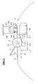
- numeral 1 denotes a printing drum which is supported by a structure not shown in the drawings so as to be rotatable around its central axial line, and is rotatively actuated in clockwise direction around its central axial line as seen in Figure 1.
- a part of the outer circumferential surface of the printing drum 1 is formed as a flat region 3, and a fixed clamping plate 5 consisting of a band member extending in the axial direction of the printing drum 1 is fixedly secured on this flat region 3.
- a pair of bearing brackets 7 are provided on either axial end of this flat region 3, and rotatably support a support shaft 9 extending in the axial direction of the printing drum 1.
- a moveable clamping plate 11 consisting of a band member is fixedly secured to the support shaft 9. The moveable clamping plate 11 thus can angularly move along with the support shaft 9 between a clamping position for opposing the fixed clamping plate 5, and an unclamping position which is angularly displaced from the clamping position in clockwise direction as seen in Figure 1 by 180 degrees.
- a clamping sheet spring 13 is mounted on a free end of the moveable clamping plate 11, and engages with a groove 6 of the fixed clamping plate 5 when the moveable clamping plate 11 is at the clamping position for elastically clamping a master plate sheet between the moveable clamping plate 11 and the fixed clamping plate 5.
- the fixed clamping plate 5 is not required to be a magnetic plate for magnetically attracting the moveable clamping plate 11.
- a worm gear 15 is fixedly mounted on an end of the support shaft 9.
- a recess 17 is formed in the flat region 3 of the printing drum 1 for receiving the worm gear 15, and a motor 19 serving as the electric actuator is fixedly secured in this recess 17.
- a worm 23 is mounted on the output shaft 21 of the motor 19, and always meshes with the worm gear 15.
- the flat region 3 of the printing drum 1 is provided with a pair of electric collector members 27 received in separate insulating cases 25.
- Each of the electric collector members 27 is urged toward an upper opening 31 of the associated insulating case 25 by a compression coil spring 29 accommodated in the case 25, and is electrically connected to a lead wire 35 of the motor 19 via a connecting terminal plate 33 of the associated insulating case 25.
- the flat region 3 is further provided with a pair of tapered positioning rings 37 each aligning with the upper opening 31 of the associated one of the insulating cases 25.
- a vertical actuator 41 is mounted on a fixed member 39 of the printer.
- a power supply box 45 is suspended from a vertically moveable rod 43 of the vertical actuator 41.
- a pair of power supply pins 47 are provided in the power supply box 45. Each of the power supply pins 47 projects downward from the power supply box 45, and, when the printing drum 1 is in the illustrated angular position, fits into the upper opening 31 of the associated insulating case 25 via the tapered positioning ring 37 so as to be brought in contact with the associated collector member 27.
- the power supply box 45 is provided with a pair of insulating sleeves 49 each of which is fitted on an associated one of the power supply pins 47.
- Each of the insulating sleeves 49 is placed at a lower position for entirely covering the associated power supply pin 47 under the spring force of a spring 51 when the power supply pin 47 is at its upper position spaced from the collector member 27 as illustrated in Figure 1, and is moved upward relative to the power supply box 45 against the spring force of the spring 51 by engaging with the tapered positioning ring 37 at its tapered tip 50 so as to expose the power supply pin 47 when the power supply pin 47 is at its lower position and is in contact with the associated collector member 27 as illustrated in Figure 3.
- the power supply box 45 is moved vertically between its upper position in which the power supply pins 47 are spaced from the collector members 27, and its lower position in which the power supply pins 47 are in contact with the collector members 27.
- the two power supply pins 47 are connected to a motor drive circuit 55 via lead wires 53.
- the motor drive circuit 55 controls the supply of electric power to the motor 19 by feeding a power supply control signal with a control unit 57, and changes the direction of rotation of the motor 19 by feeding a direction control signal with the control unit 57.
- the control unit 57 comprises a microcomputer which receives a clamp command signal and an unclamp command signal, and receives an electric current value signal corresponding to the electric current supplied to the motor 19 via a current detection circuit 59.
- the control unit 57 supplies a motor normal direction control signal and a power supply control signal to the motor drive circuit 55.
- the control unit 57 supplies a motor reverse direction control signal and a power supply control signal to the motor drive circuit 55.
- the control unit 57 supplies a current stop signal to the motor drive circuit 55, and controls the operation of the vertical actuator 41 accordingly.
- the two insulating sleeves 49 are lifted relative to the power supply box 45 against the spring force of the springs 51.
- the two power supply pins 47 are exposed, and are fitted into the upper openings 31 of the insulating case 25 via the associated tapered positioning rings 37, and are brought into contact with the collector members 27 in an electroconductive relationship.
- the lead wires 35 of the printing drum 1 and the lead wires 53 of the fixed member 39 are electroconductively connected with each other, and the motor 19 and the motor drive circuit 55 are electrically connected with each other.
- the control unit 57 supplies a motor reverse control signal and an electric power supply control signal to the motor drive circuit 55, the motor 19 is drivingly rotated in the reverse direction, and the rotation of the motor 19 is transmitted to the support shaft 9 via the worm 23 and the worm gear 15, so as to turn the moveable clamping plate 11 in clockwise direction or, in other words, toward the unclamping position.
- the moveable clamping plate 11 is moved away from the fixed clamping plate 5, and, if a master sheet has been clamped between the moveable and fixed clamping plates 11 and 5, it is released.
- the master plate sheet which has been clamped is released from the printing drum 1, and a leading edge of a new master plate sheet is placed on the fixed clamping plate 5.
- a clamp command signal is supplied to the control unit 57.
- a motor normal direction control signal and an electric power control signal are supplied from the control unit 57 to the motor drive circuit 55, and the motor 19 is driven in the normal direction.
- the rotation of the motor 19 is transmitted to the support shaft 9 via the worm 23 and the worm gear 15, and the moveable clamping plate 11 is turned in counter clockwise direction in Figure 1, or toward the clamping position.
- the movable clamping plate 11 is engaged with the fixed clamping plate 5, and the clamping sheet spring 13 is fitted into the groove 6 of the fixed clamping plate 5 so as to elastically clamp the master plate sheet against the fixed clamping plate 5.
- the moveable clamping plate 11 If the moveable clamping plate 11 has reached the clamping position by the normal rotation of the motor 19 or the moveable clamping plate 11 has already been placed at the clamping position by an erroneous operation, the moveable clamping plate 11 cannot turn any further in counter clockwise direction as seen in Figure 1 with the result that the load of the motor 19 is increased, and the electric current detected by the electric current detection circuit 59 exceeds the prescribed value. As a result, the control unit 57 issues an electric current supply stop signal to the motor drive circuit 55, and the normal rotation of the motor 19 is stopped.
- an error process may be executed.
- the moveable clamping plate 11 is self-retained at the clamping position, and the clamped state of the master plate sheet can be maintained without any continued consumption of power.
- the power supply box 45 is lifted by the vertical actuator 41 until the two power supply pins 47 are moved away from the collector members 27 with the result that the insulating sleeves 49 are moved away from the associated tapered positioning rings 37, and cover the entire power supply pins 47.
- the printing drum 1 can rotate freely, and the entire power supply pins 47 are covered by the insulating sleeves 49 for preventing short-circuiting and electric shock.
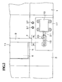
- Figures 5 and 6 show another embodiment of the master plate sheet clamping device for a printer according to the present invention.
- the parts corresponding to those illustrated in Figures 1 through 4 are denoted with like numerals.
- a pair of collector contact plates 63 and 65 are attached to the outer circumferential surface of the support shaft 9 at an angular phase difference of 180 degrees with gaps 61 defined therebetween, and are electrically connected to the motor 19 via lead wires 35.
- a capacitors 68 is serially connected to each of the lead wires 35.
- the power supply box 45 is provided with a pair of power supply brushes 67 and 69. With the vertical movement of the power supply box 45 caused by the vertical actuator 41, the power supply brushes 67 and 69 are brought into contact with the outer circumferential surface of the support shaft 9 from opposite directions.
- One of the power supply brushes 67 is connected to the positive terminal of the motor drive circuit 55, and the other power supply brush 69 is connected to the negative terminal of the motor drive circuit 55, by lead wires 53, respectively.
- a spur gear 71 is fixedly fitted on an output shaft 21 of the motor 19 mounted on the printing drum 1, and always meshes with another spur gear 73 fixedly fitted on the support shaft 9.
- a tension coil spring 79 is engaged between a pin 75 provided on the spur gear 73 and a spring engagement piece 77 mounted on the printing drum 1, and urges the moveable clamping plate 11 as a reversible spring either to the clamping position or to the unclamping position depending on which side of a neutral position the clamping plate 11 is located.
- electric power is supplied to the motor 19 via the power supply brushes 67 and 69, and the power collector plates 63 and 65.
- the power collector plates 63 and 65 undergo a 180 degree rotation between the clamping position and the unclamping position.
- the power supply brush 67 contacts the power collector plate 65 while the power supply brush 69 contacts the power collector plate 63.
- the unclamping position the power supply brush 67 contacts the power collector plate 63 while the power supply brush 69 contacts the collector plate 65. Therefore, the polarity of the electric power supplied to the motor 19 reverses between the clamping and unclamping positions.
- the motor drive circuit 55 is not required to carry out the control for reversing the rotational direction of the motor 19. Furthermore, because the polarity of the electric power supplied to the motor 19 is solely determined by the angular position of the support shaft 9, no error can occur in the rotational direction of the motor 19.
- the supply of electric power to the motor 19 is stopped when the support shaft 9 is in such an angular position that the power supply brushes 67 and 69 are placed on the gaps 61, and the rotation of the motor 19 is continued thereafter for a short time interval by virtue of the electric charge stored in the capacitors 68.
- the moveable clamping plate 11 is moved either to the clamping position or the unclamping position assisted by the inertia force and the spring force of the tension coil spring 79.
- the power supply members on the side of the fixed member is electrically connected to the power collector members on the side of the printing drum, and electric power is thereby supplied to the motor (electric actuator). Because the moveable clamping member is moved between the clamping position and the unclamping position by the motor mounted on the printing drum, no large solenoid device is required for moving the motor between the meshing position and the release position, and the problem of having a difficulty in properly meshing the gear on the motor output shaft with the gear on the support shaft can be avoided.
- the printing drum is not subjected to any rotational force when moving the moveable clamping member, there is no need to provide a mechanism for preventing the rotation of the printing drum due to the reaction force. All these factors contribute to the reliable clamping and unclamping action of the present invention with a highly simple structure.
Landscapes
- Supply, Installation And Extraction Of Printed Sheets Or Plates (AREA)
- Handling Of Cut Paper (AREA)
Claims (7)
- Masterplattenfolien-Klemmvorrichtung für eine Rotationsdruckmaschine, die eine Masterplattenfolie auf der Außenumfangsfläche einer drehangetriebenen Drucktrommel klemmt, bestehend aus:einem verstellbaren Klemmelement (11), das an der Drucktrommel angeordnet und an einer Tragstange (9) befestigt, um zwischen einer Klemmposition zum Klemmen einer Masterplattenfolie an der Außenumfangsfläche der Drucktrommel (1) und einer Abspannposition zum Freigeben der Masterpattenfolie von der Drucktrommel (1) verstellbar zu sein; einem Motor (19), der an dar Drucktrommel (1) zum Betätigen des verstellbaren Klemmelements (11) zwischen der Klemmposition und der Abspannposition angeordnet ist; einem Übertragungselement (15, 23; 21, 23), das an der Drucktrommel (1) zur Übertragung der Drehung des Motors (19) auf die Tragstange (9) angeordnet ist; und einer Versorgungseinrichtung (27, 45, 47; 63, 65, 67, 69) zur Versorgung des Motors (19) mit elektrischer Energie,
wobei die Einrichtung zur Versorgung mit elektrischer Energie ein Energiekollektorelement (27; 63, 65), das mit dem Motor (19) elektrisch verbunden und an der Drucktrommel (1) angeordnet ist, und ein Energieversorgungselement (45, 47; 67, 69) aufweist, das an eine externe Energiequelle (55) angeschlossen und an einem festen Element (39) der Druckmaschine zur selektiven Verstellung in Kontakt mit und getrennt vom Energiekollektorelement (27; 63, 65) angeordnet ist. - Masterplattenfolien-Klemmvorrichtung nach Anspruch 1,
dadurch gekennzeichnet, daß
das Energieversorgungselement (45) Wenigstens einen Stift (47) auweist, und daß das Energiekollektorelement (27) eine Sockeleinrichtung (37) zur Aufnahme des Stiftes (27) aufweist, um einen elektrischen Kontakt zwischen dem Energieversorgungselement (45) und dem Energiekollektorelement (27) herzustellen. - Masterplattenfolien-Klemmvorrichtung nach Anspruch 2,
dadurch gekennzeichnet, daß
das Energieversorgungselement (45) außerdem eine Isolierhülse (49) aufweist, die verschiebbar auf den Stift (47) aufgesetzt und zurückziehbar ist, um den Stift (47) freizulegen, wenn er in die Sockeleinrichtung (37) eingreift. - Masterplaftenfolien-Klemmvorrichtung nach Anspruch 1,
dadurch gekennzeichnet, daß
eine Steuereinrichtung (57) zur Steuerung des Motors (19), die eine Detektoreinrichtung (59) für elektrischen Strom aufweist, um die Größe des dem Motor (19) zugeführten elektrischen Stromes zu ermitteln, und die den Betrieb des Motors (19) stoppt, wenn der von der Detektoreinrichtung (59) ermittelte elektrische Strom einen Sollwert überschreitet, der anzeigt, daß das verstellbare Klemmelement (11) die Klemmposition oder die Abspannposition erreicht. - Masterplartenfolien-Klemmvorrichtung nach Anspruch 1,
dadurch gekennzeichnet, daß
das verstellbare Klemmelement (11) ein Federelement (13) hat, um die Masterplattenfolie gegen die Außenumfangsfläche der Druckplatte (1) federnd zu klemmen. - Masterplattenfolien-Klemmvorrichtung nach Anspruch 1,
dadurch gekennzeichnet, daß
das Energieversorgungselement (45) ein Paar Energieversorgungs-Bürstenelemente (67, 69), und das Energiekollektorelement (63, 65) einen Kommutator mit einem Paar elektrisch leitender Segmente (63, 65) und Isolierspalten (61) zwischen den Segmenten (63, 65), die von den Energieversorgungs-Bürstenelementen (67, 69) kontaktiert werden können, aufweist, wobei die Segmente (63, 65) und die Spalte (61) die Richtung und das Ende der Bewegung des Motors (19) bestimmen. - Masterplattenfolien-Klemmvorrichtung nach Anspruch 1,
gekennzeichnet durch
eine Federeinrichtung (79), um das versteilbare Klemmelement (11) in die Klemmposition oder die Abspannposition in Abhängigkeit davon zu drücken, auf weicher Seite einer neutralen Position sich das verstellbare Klemmelement (11) befindet.
Applications Claiming Priority (2)
| Application Number | Priority Date | Filing Date | Title |
|---|---|---|---|
| JP297135/92 | 1992-11-06 | ||
| JP29713592A JP3290720B2 (ja) | 1992-11-06 | 1992-11-06 | 印刷装置の原紙クランプ装置 |
Publications (2)
| Publication Number | Publication Date |
|---|---|
| EP0596746A1 EP0596746A1 (de) | 1994-05-11 |
| EP0596746B1 true EP0596746B1 (de) | 1999-04-14 |
Family
ID=17842666
Family Applications (1)
| Application Number | Title | Priority Date | Filing Date |
|---|---|---|---|
| EP93308858A Expired - Lifetime EP0596746B1 (de) | 1992-11-06 | 1993-11-05 | Klemmvorrichtung für Originaldruckplatten bei Rotationsdruckmaschinen |
Country Status (4)
| Country | Link |
|---|---|
| US (1) | US5456177A (de) |
| EP (1) | EP0596746B1 (de) |
| JP (1) | JP3290720B2 (de) |
| DE (1) | DE69324440T2 (de) |
Families Citing this family (4)
| Publication number | Priority date | Publication date | Assignee | Title |
|---|---|---|---|---|
| JP3292427B2 (ja) * | 1994-11-25 | 2002-06-17 | 理想科学工業株式会社 | 輪転式孔版印刷機の孔版原紙始端装着装置 |
| US6505551B1 (en) * | 1999-10-05 | 2003-01-14 | Riso Kagaku Corporation | Stencil printing machine having means to hold both ends of stencil sheet |
| JP3631929B2 (ja) * | 1999-11-11 | 2005-03-23 | 理想科学工業株式会社 | 輪転式孔版印刷機の孔版原紙始端装着装置 |
| FR2898297B1 (fr) * | 2006-03-08 | 2010-03-12 | Goss Int Montataire Sa | Cylindre de plaque et presse rotative correspondante. |
Citations (1)
| Publication number | Priority date | Publication date | Assignee | Title |
|---|---|---|---|---|
| EP0508113A1 (de) * | 1991-04-10 | 1992-10-14 | MAN Roland Druckmaschinen AG | Vorrichtung zum lagegenauen Schnellklemmen und Spannen von Druckplatten auf dem Plattenzylinder von Druckmaschinen |
Family Cites Families (11)
| Publication number | Priority date | Publication date | Assignee | Title |
|---|---|---|---|---|
| US1619086A (en) * | 1920-09-20 | 1927-03-01 | Benjamin F Oldmixon | Terminal connecter |
| US3567175A (en) * | 1968-10-08 | 1971-03-02 | Stile Craft Mfg Inc | Quick release coupling |
| US3664260A (en) * | 1970-06-15 | 1972-05-23 | Addressograph Multigraph | Master sheet retainer for printing machines |
| US3768406A (en) * | 1972-07-03 | 1973-10-30 | Polygraph Leipzig | Sheet gripper |
| DE3721965A1 (de) * | 1987-07-03 | 1989-01-12 | Stewing Gmbh & Co Kg | Kabelendstecker fuer den aussenleiter eines koaxialkabels |
| US4943045A (en) * | 1988-08-15 | 1990-07-24 | Tektronix, Inc. | Printer sheet feed system |
| JP2828462B2 (ja) * | 1989-06-22 | 1998-11-25 | 理想科学工業株式会社 | 孔版印刷装置 |
| DE4137948A1 (de) * | 1990-11-19 | 1992-05-21 | Sumitomo Heavy Industries | Druckplatten-spannvorrichtung fuer eine druckmaschine |
| JP2828355B2 (ja) * | 1990-12-28 | 1998-11-25 | リョービ株式会社 | オフセット印刷機、刷版および画像位置読み取り方法 |
| JP2505387Y2 (ja) * | 1991-02-12 | 1996-07-31 | 矢崎総業株式会社 | 端子金具と防水栓の固定構造 |
| US5253583A (en) * | 1991-03-04 | 1993-10-19 | Fuji Kikai Kogyo Kabushiki Kaisha | Device for positioning printing material for use in a printing apparatus |
-
1992
- 1992-11-06 JP JP29713592A patent/JP3290720B2/ja not_active Expired - Fee Related
-
1993
- 1993-11-05 DE DE69324440T patent/DE69324440T2/de not_active Expired - Fee Related
- 1993-11-05 EP EP93308858A patent/EP0596746B1/de not_active Expired - Lifetime
- 1993-11-08 US US08/148,860 patent/US5456177A/en not_active Expired - Fee Related
Patent Citations (1)
| Publication number | Priority date | Publication date | Assignee | Title |
|---|---|---|---|---|
| EP0508113A1 (de) * | 1991-04-10 | 1992-10-14 | MAN Roland Druckmaschinen AG | Vorrichtung zum lagegenauen Schnellklemmen und Spannen von Druckplatten auf dem Plattenzylinder von Druckmaschinen |
Also Published As
| Publication number | Publication date |
|---|---|
| DE69324440T2 (de) | 1999-12-16 |
| JPH06143783A (ja) | 1994-05-24 |
| DE69324440D1 (de) | 1999-05-20 |
| US5456177A (en) | 1995-10-10 |
| EP0596746A1 (de) | 1994-05-11 |
| JP3290720B2 (ja) | 2002-06-10 |
Similar Documents
| Publication | Publication Date | Title |
|---|---|---|
| EP0596746B1 (de) | Klemmvorrichtung für Originaldruckplatten bei Rotationsdruckmaschinen | |
| US20040195750A1 (en) | Electric clamping apparatus with manual control | |
| KR200177127Y1 (ko) | 크레인용 강판코일 리프터의 전원 공급장치 | |
| CN211337926U (zh) | 一种换向校正装置及其led灯珠生产设备 | |
| US20240009783A1 (en) | Safe screwing device having compliance mechanism | |
| SU831606A1 (ru) | Модуль промышленного робота | |
| JPH06217497A (ja) | 回転検出手段付モータ | |
| SU1709417A1 (ru) | Автоматическа лини дл сборки магнитной системы электромагнитного реле | |
| JPH0332530A (ja) | パーツの迅速移送装置 | |
| SU1203009A1 (ru) | Предохранительное устройство дл гибкого токоподвода грузоподъемного крана | |
| CN108827227B (zh) | 一种汽车微电机安装角度定位装置 | |
| CN223315904U (zh) | T型电感磁芯上料装置 | |
| KR0177664B1 (ko) | 다수의 구멍을 가진 부품의 위치결정 유니트 | |
| SU1665419A1 (ru) | Устройство дл намотки катушек на кольцевые сердечники | |
| CN114284796B (zh) | 一种上电装置及真空处理装置 | |
| SU1430283A1 (ru) | Магнитный схват | |
| DK180788B1 (en) | Secure screw device with compliance mechanism | |
| JPH0315311Y2 (de) | ||
| US2940031A (en) | Shaft-positioning servomotor mechanism | |
| JP2530195B2 (ja) | ストロ―ク型ステップモ―タ | |
| SU1618645A1 (ru) | Устройство дл перемещени деталей | |
| SU1222142A1 (ru) | Устройство дл сборки полупроводниковых приборов | |
| JPS5934102Y2 (ja) | タツプ切換装置 | |
| JP2554095B2 (ja) | Xyプロッタのペン交換装置 | |
| CN116710237A (zh) | 具有顺应性机构的安全旋拧装置 |
Legal Events
| Date | Code | Title | Description |
|---|---|---|---|
| PUAI | Public reference made under article 153(3) epc to a published international application that has entered the european phase |
Free format text: ORIGINAL CODE: 0009012 |
|
| 17P | Request for examination filed |
Effective date: 19931115 |
|
| AK | Designated contracting states |
Kind code of ref document: A1 Designated state(s): DE FR GB |
|
| 17Q | First examination report despatched |
Effective date: 19961007 |
|
| GRAG | Despatch of communication of intention to grant |
Free format text: ORIGINAL CODE: EPIDOS AGRA |
|
| GRAG | Despatch of communication of intention to grant |
Free format text: ORIGINAL CODE: EPIDOS AGRA |
|
| GRAH | Despatch of communication of intention to grant a patent |
Free format text: ORIGINAL CODE: EPIDOS IGRA |
|
| GRAH | Despatch of communication of intention to grant a patent |
Free format text: ORIGINAL CODE: EPIDOS IGRA |
|
| GRAA | (expected) grant |
Free format text: ORIGINAL CODE: 0009210 |
|
| AK | Designated contracting states |
Kind code of ref document: B1 Designated state(s): DE FR GB |
|
| REF | Corresponds to: |
Ref document number: 69324440 Country of ref document: DE Date of ref document: 19990520 |
|
| ET | Fr: translation filed | ||
| PLBE | No opposition filed within time limit |
Free format text: ORIGINAL CODE: 0009261 |
|
| 26N | No opposition filed | ||
| REG | Reference to a national code |
Ref country code: GB Ref legal event code: IF02 |
|
| PGFP | Annual fee paid to national office [announced via postgrant information from national office to epo] |
Ref country code: DE Payment date: 20041028 Year of fee payment: 12 |
|
| PGFP | Annual fee paid to national office [announced via postgrant information from national office to epo] |
Ref country code: GB Payment date: 20041104 Year of fee payment: 12 |
|
| PGFP | Annual fee paid to national office [announced via postgrant information from national office to epo] |
Ref country code: FR Payment date: 20041109 Year of fee payment: 12 |
|
| PG25 | Lapsed in a contracting state [announced via postgrant information from national office to epo] |
Ref country code: GB Free format text: LAPSE BECAUSE OF NON-PAYMENT OF DUE FEES Effective date: 20051105 |
|
| PG25 | Lapsed in a contracting state [announced via postgrant information from national office to epo] |
Ref country code: DE Free format text: LAPSE BECAUSE OF NON-PAYMENT OF DUE FEES Effective date: 20060601 |
|
| GBPC | Gb: european patent ceased through non-payment of renewal fee |
Effective date: 20051105 |
|
| PG25 | Lapsed in a contracting state [announced via postgrant information from national office to epo] |
Ref country code: FR Free format text: LAPSE BECAUSE OF NON-PAYMENT OF DUE FEES Effective date: 20060731 |
|
| REG | Reference to a national code |
Ref country code: FR Ref legal event code: ST Effective date: 20060731 |