EP0594954A1 - Serrure, en particulier pour bicyclette - Google Patents
Serrure, en particulier pour bicyclette Download PDFInfo
- Publication number
- EP0594954A1 EP0594954A1 EP93112238A EP93112238A EP0594954A1 EP 0594954 A1 EP0594954 A1 EP 0594954A1 EP 93112238 A EP93112238 A EP 93112238A EP 93112238 A EP93112238 A EP 93112238A EP 0594954 A1 EP0594954 A1 EP 0594954A1
- Authority
- EP
- European Patent Office
- Prior art keywords
- locking
- steering shaft
- locking mechanism
- lock according
- lock
- Prior art date
- Legal status (The legal status is an assumption and is not a legal conclusion. Google has not performed a legal analysis and makes no representation as to the accuracy of the status listed.)
- Withdrawn
Links
Images
Classifications
-
- B—PERFORMING OPERATIONS; TRANSPORTING
- B62—LAND VEHICLES FOR TRAVELLING OTHERWISE THAN ON RAILS
- B62H—CYCLE STANDS; SUPPORTS OR HOLDERS FOR PARKING OR STORING CYCLES; APPLIANCES PREVENTING OR INDICATING UNAUTHORIZED USE OR THEFT OF CYCLES; LOCKS INTEGRAL WITH CYCLES; DEVICES FOR LEARNING TO RIDE CYCLES
- B62H5/00—Appliances preventing or indicating unauthorised use or theft of cycles; Locks integral with cycles
- B62H5/02—Appliances preventing or indicating unauthorised use or theft of cycles; Locks integral with cycles for locking the steering mechanism
-
- B—PERFORMING OPERATIONS; TRANSPORTING
- B62—LAND VEHICLES FOR TRAVELLING OTHERWISE THAN ON RAILS
- B62H—CYCLE STANDS; SUPPORTS OR HOLDERS FOR PARKING OR STORING CYCLES; APPLIANCES PREVENTING OR INDICATING UNAUTHORIZED USE OR THEFT OF CYCLES; LOCKS INTEGRAL WITH CYCLES; DEVICES FOR LEARNING TO RIDE CYCLES
- B62H5/00—Appliances preventing or indicating unauthorised use or theft of cycles; Locks integral with cycles
- B62H5/08—Appliances preventing or indicating unauthorised use or theft of cycles; Locks integral with cycles preventing the drive
- B62H5/10—Appliances preventing or indicating unauthorised use or theft of cycles; Locks integral with cycles preventing the drive acting on a pedal crank
Definitions
- the invention relates to a lock, in particular for a bicycle or the like with a locking unit and a locking mechanism.
- Many known locks for motor-driven or foot-operated bicycles or the like consist of a locking unit which is fixed to a rod part, e.g. B. a rear strut, and a locking mechanism engaging in the rear wheel.
- Other known locks are padlocks or cable locks which can be separated from the bicycle and which can optionally be placed around the frame, front and / or rear wheel.
- the aim of the present invention is to provide a lock in particular for a bicycle or the like so that the security provided by the lock against theft of the bicycle or the like is increased and at the same time the weight of the lock is reduced.
- the locking mechanism is provided so that it engages directly in a form-fitting manner in a drive crankshaft and / or a steering shaft, both the drive mechanism, such as. B. the crank, and possibly also the handlebars, so that the bike or the like can only be removed in a blocked state.
- the locking mechanism of the lock according to the invention preferably engages both in the drive crankshaft and in the steering shaft at the same time.
- the term bicycle is understood to mean both conventional bicycles and tricycles driven by pedals and light motorcycles, such as mopeds and mopeds.
- the drive crankshaft and / or the steering shaft has a peripheral recess or an opening into which a locking member of the locking mechanism engages.
- the locking mechanism is provided inside a frame tube of the bicycle or the like connecting a crankshaft bearing housing of the drive crank and a steering shaft bearing housing of the steering shaft.
- the locking mechanism can also be provided within a special tube that runs in parallel with the frame tube mentioned.
- peripheral recess or the breakthrough of the steering shaft and the locking member engaging therein are preferably provided such that the steered wheel is strongly driven in the locked state.
- the locking unit which actuates the locking mechanism can be a conventional cylinder lock which is permanently connected to the bicycle or the like.
- crankshaft bearing housing in particular in its axial direction
- steering shaft bearing housing also in its axial direction or on the above-mentioned frame tube, for example in one piece therewith.
- the locking mechanism can also be operated by a remotely controllable, electromagnetic or electromotive locking unit.
- the locking mechanism does not inadvertently engage the drive crankshaft without the clamping unit acting can, the locking mechanism is biased by spring force against its engagement in the drive crankshaft.
- the locking action of the locking mechanism which takes place against the biasing spring force can advantageously be triggered and supported in that the locking unit moves the locking mechanism into a defined locking preparation position, in which the locking members are not yet in engagement with the drive crankshaft and the steering shaft, and thereby that one Rotation of the steering shaft into the position provided for locking causes the final locking, the prestressing spring force being overcome by this rotation of the steering shaft.
- the locking mechanism can have a lever linkage.
- the locking mechanism can have a cable cable gear.
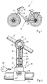
- a conventional, pedal-driven bicycle 1 shown in FIG. 1 has a handlebar 10, a steering shaft bearing housing 11, a steering shaft (front wheel fork strut) 13, a frame tube 12 connecting the steering shaft bearing housing 11 with a crankshaft bearing housing, and a crank drive 15.
- a first embodiment of a lock 20 according to the invention shown in FIG. 2 has a locking unit 21 and a locking mechanism 22.
- the locking unit 21 is a cylinder lock in a conventional manner and can be opened or locked with a key 28.
- the cylinder axis of the cylinder lock 21 is provided in the axial direction of a crankshaft bearing housing 16.
- the locking mechanism 22 shown schematically in FIG. 2 has a locking member 23 and 24 at opposite ends. The locking member 23 engages in a peripheral recess or an opening 19 of the steering shaft 13, which is mounted in the steering shaft bearing housing 11.
- the locking mechanism 22 shown in simplified form in FIG. 2 as a linkage mechanism, sits in the interior of the frame tube 12 and can, for example, consist of rods which can be moved telescopically into one another and which are closed by the locking unit 21 in opposite directions are linearly displaceable. So that the opposing locking members 23 and 24 cannot inadvertently engage in the recesses 19 and 18 of the steering shaft 13 and the crankshaft 17, respectively, the linkage parts of this locking mechanism 22 are prestressed against their directions of engagement by coil springs 26 and 27, respectively.
- the coil springs 26 and 27 are each supported between a collar 25 of the inner linkage part and the steering shaft bearing housing 11 and between a further collar 25 'of the outer linkage part and the crankshaft bearing housing 16. When the locking unit 21 is closed by means of the key 28, the springs 26 and 27 are accordingly compressed.
- the locking unit 21 is non-detachably connected to the crankshaft bearing housing 16, for. B. welded or molded in one piece.
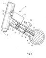
- FIG. 3 shows a further embodiment 30 of a lock according to the invention, in which a locking unit 31 is non-releasably attached to the frame tube 12 in the axial direction thereof and to the steering shaft bearing housing 11.
- the locking mechanism consisting of a linkage 32 which has a collar 35 against which a coil spring 36 is supported.
- the helical spring 36 is provided so that the locking member 34 does not inadvertently engage in the recess 18 in the crankshaft 17.
- the linkage 32 is guided in a guide bush 37 in the longitudinal direction of the frame tube 12.
- the cylinder axis of the cylinder lock 31 can also be made parallel to the axis of rotation of the steering shaft 13, so that the key 38 can be inserted into the cylinder lock 31 from above.
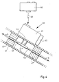
- FIG. 4 shows a further embodiment 40 of a lock according to the invention, in which a locking mechanism, which is represented by two rods 42 and 42 ', can be actuated by means of a locking unit 41 which can be remotely controlled by a remote control unit 46, for example by infrared rays 48.
- the locking unit 41 can be equipped with a battery 45 and contain an electromotive or electromagnetically operating closing-opening actuator.
- the latter has a mechanical locking member 44 which is rotated in the direction of arrow I and pushes the two rods 42 and 42 'in the direction of arrows L and K into the locking position.
- the rods 42 and 42 ' are also, as in the previous exemplary embodiments, inside the frame tube 12 and are mounted there in longitudinally displaceable fashion in guide bushes 47 and 47'.
- the locking mechanism consists of a lever linkage
- the locking mechanism can alternatively or additionally also have a cable pull inside the frame tube.
- the locking cylinder or the locking unit can move the locking mechanism in a defined locking preparation position into a position in which the locking members are not yet in engagement with the drive crankshaft and the steering shaft, in which case the final locking is effected by rotating the steering shaft into the position provided for locking, the prestressing spring force of the prestressing springs being overcome by this rotation of the steering shaft.
Landscapes
- Engineering & Computer Science (AREA)
- Mechanical Engineering (AREA)
- Lock And Its Accessories (AREA)
Applications Claiming Priority (2)
| Application Number | Priority Date | Filing Date | Title |
|---|---|---|---|
| DE9214669U | 1992-10-29 | ||
| DE9214669U DE9214669U1 (fr) | 1992-04-13 | 1992-10-29 |
Publications (1)
| Publication Number | Publication Date |
|---|---|
| EP0594954A1 true EP0594954A1 (fr) | 1994-05-04 |
Family
ID=6885406
Family Applications (1)
| Application Number | Title | Priority Date | Filing Date |
|---|---|---|---|
| EP93112238A Withdrawn EP0594954A1 (fr) | 1992-10-29 | 1993-07-30 | Serrure, en particulier pour bicyclette |
Country Status (1)
| Country | Link |
|---|---|
| EP (1) | EP0594954A1 (fr) |
Cited By (7)
| Publication number | Priority date | Publication date | Assignee | Title |
|---|---|---|---|---|
| WO1999008924A1 (fr) * | 1997-08-15 | 1999-02-25 | Lars Killmann Petersen | Dispositif de verrouillage particulierement destine aux velos |
| FR2863752A1 (fr) * | 2003-12-16 | 2005-06-17 | Jcdecaux Sa | Systeme automatique de stockage de cycles |
| CN100333936C (zh) * | 1999-10-13 | 2007-08-29 | 本田技研工业株式会社 | 电动辅助自行车 |
| EP1425211B2 (fr) † | 2001-09-13 | 2011-09-21 | Sparta B.V. | Bicyclette a propulsion auxiliaire |
| WO2017081661A1 (fr) * | 2015-11-12 | 2017-05-18 | Stefano Torelli | Dispositif antivol pour une bicyclette et bicyclette comportant ledit dispositif antivol |
| CN107200085A (zh) * | 2017-06-09 | 2017-09-26 | 浙江绿源电动车有限公司 | 转向锁止机构 |
| WO2018044244A1 (fr) * | 2016-08-30 | 2018-03-08 | Yasar Universitesi | Mécanisme d'immobilisation monté sur le cadre de la bicyclette permettant d'empêcher le mouvement de ladite bicyclette |
Citations (3)
| Publication number | Priority date | Publication date | Assignee | Title |
|---|---|---|---|---|
| CH179307A (de) * | 1934-11-06 | 1935-08-31 | Sartori Leander | Vorrichtung an Fahrrädern zum Verstellen der Lenkstange auf dem Schaftrohr und Sichern des Fahrrades gegen unbefugte Benutzung. |
| DE9005510U1 (fr) * | 1990-05-15 | 1990-08-09 | Gerber, Werner, 6057 Dietzenbach, De | |
| DE4019478A1 (de) * | 1989-06-20 | 1991-01-10 | Honda Motor Co Ltd | Elektrische spannungsversorgungs-kontrolleinheit fuer ein kraftfahrzeug |
-
1993
- 1993-07-30 EP EP93112238A patent/EP0594954A1/fr not_active Withdrawn
Patent Citations (3)
| Publication number | Priority date | Publication date | Assignee | Title |
|---|---|---|---|---|
| CH179307A (de) * | 1934-11-06 | 1935-08-31 | Sartori Leander | Vorrichtung an Fahrrädern zum Verstellen der Lenkstange auf dem Schaftrohr und Sichern des Fahrrades gegen unbefugte Benutzung. |
| DE4019478A1 (de) * | 1989-06-20 | 1991-01-10 | Honda Motor Co Ltd | Elektrische spannungsversorgungs-kontrolleinheit fuer ein kraftfahrzeug |
| DE9005510U1 (fr) * | 1990-05-15 | 1990-08-09 | Gerber, Werner, 6057 Dietzenbach, De |
Cited By (9)
| Publication number | Priority date | Publication date | Assignee | Title |
|---|---|---|---|---|
| WO1999008924A1 (fr) * | 1997-08-15 | 1999-02-25 | Lars Killmann Petersen | Dispositif de verrouillage particulierement destine aux velos |
| CN100333936C (zh) * | 1999-10-13 | 2007-08-29 | 本田技研工业株式会社 | 电动辅助自行车 |
| EP1425211B2 (fr) † | 2001-09-13 | 2011-09-21 | Sparta B.V. | Bicyclette a propulsion auxiliaire |
| FR2863752A1 (fr) * | 2003-12-16 | 2005-06-17 | Jcdecaux Sa | Systeme automatique de stockage de cycles |
| WO2005068280A1 (fr) * | 2003-12-16 | 2005-07-28 | Jcdecaux Sa | Systeme automatique de stockage de cycles |
| US7471191B2 (en) | 2003-12-16 | 2008-12-30 | J. C. Decaux Sa | Automatic cycle storage system |
| WO2017081661A1 (fr) * | 2015-11-12 | 2017-05-18 | Stefano Torelli | Dispositif antivol pour une bicyclette et bicyclette comportant ledit dispositif antivol |
| WO2018044244A1 (fr) * | 2016-08-30 | 2018-03-08 | Yasar Universitesi | Mécanisme d'immobilisation monté sur le cadre de la bicyclette permettant d'empêcher le mouvement de ladite bicyclette |
| CN107200085A (zh) * | 2017-06-09 | 2017-09-26 | 浙江绿源电动车有限公司 | 转向锁止机构 |
Similar Documents
| Publication | Publication Date | Title |
|---|---|---|
| EP3590813B1 (fr) | Bicyclette pourvue d'un entraînement auxiliaire fonctionnant sur batterie et cadre de bicyclette correspondant | |
| EP3680160B1 (fr) | Embrayage compact à verrouillage automatique | |
| DE102004011173A1 (de) | Abnehmbare Windschutzscheibe für Motorräder | |
| EP0943525A2 (fr) | Colonne de direction d'un véhicule automobile | |
| DE102010052546A1 (de) | Lenkeinrichtung | |
| DE102011079595B4 (de) | Fahrrad mit einem klappbaren Rahmen | |
| DE4438210B4 (de) | Schloß, insbesondere Mehrriegelschloß, mit einem Fremdantrieb | |
| EP0594954A1 (fr) | Serrure, en particulier pour bicyclette | |
| DE10320447A1 (de) | Kraftfahrzeugtürverschluss | |
| EP0541736B1 (fr) | Moyeu a serrage rapide pour bicyclettes | |
| DD219985A5 (de) | Ausschwingtuer mit betaetigungseinrichtung | |
| DE102020117942A1 (de) | Elektrischer Hilfsantrieb für ein Fahrrad | |
| EP1200302B1 (fr) | Dispositif d'antivol pour bicyclettes | |
| DE4222526C2 (fr) | ||
| DE102006013085B3 (de) | Lenksäulenbaueinheit | |
| DE3633392C2 (fr) | ||
| DE102010053179A1 (de) | Kraftfahrzeugtürverschluss | |
| DE10339542B4 (de) | Kraftfahrzeugtürverschluss | |
| DE4014158A1 (de) | Ortsfest installierte vorrichtung zur diebstahlsicherung eines fahrrads sowie fahrradstaender | |
| EP0387382B1 (fr) | Dispositif de manivelle pour bicyclette, tricycle ou similaire | |
| DE3109870C2 (de) | Einrichtung zum Zerstören von Scheiben eines Fahrzeuges | |
| DE2624155C3 (de) | Diebstahlsicherung für Sturzhelme an Zweirad - Fahrzeugen | |
| DE10240570B4 (de) | Rahmenschloß | |
| DE4214457A1 (de) | Fahrerhaus eines lastkraftwagens | |
| WO2001098135A1 (fr) | Antivol pour cycles |
Legal Events
| Date | Code | Title | Description |
|---|---|---|---|
| PUAI | Public reference made under article 153(3) epc to a published international application that has entered the european phase |
Free format text: ORIGINAL CODE: 0009012 |
|
| AK | Designated contracting states |
Kind code of ref document: A1 Designated state(s): BE DE DK FR NL |
|
| STAA | Information on the status of an ep patent application or granted ep patent |
Free format text: STATUS: THE APPLICATION IS DEEMED TO BE WITHDRAWN |
|
| 18D | Application deemed to be withdrawn |
Effective date: 19941105 |