EP0594331A1 - Capteur piézo-électrique - Google Patents
Capteur piézo-électrique Download PDFInfo
- Publication number
- EP0594331A1 EP0594331A1 EP93308001A EP93308001A EP0594331A1 EP 0594331 A1 EP0594331 A1 EP 0594331A1 EP 93308001 A EP93308001 A EP 93308001A EP 93308001 A EP93308001 A EP 93308001A EP 0594331 A1 EP0594331 A1 EP 0594331A1
- Authority
- EP
- European Patent Office
- Prior art keywords
- piezoelectric element
- piezoelectric
- piezoelectric sensor
- thermal expansion
- sensor according
- Prior art date
- Legal status (The legal status is an assumption and is not a legal conclusion. Google has not performed a legal analysis and makes no representation as to the accuracy of the status listed.)
- Granted
Links
- 239000011347 resin Substances 0.000 claims abstract description 14
- 229920005989 resin Polymers 0.000 claims abstract description 14
- 239000000853 adhesive Substances 0.000 claims abstract description 9
- 230000001070 adhesive effect Effects 0.000 claims abstract description 9
- 238000003475 lamination Methods 0.000 claims abstract description 8
- 229910001030 Iron–nickel alloy Inorganic materials 0.000 claims abstract description 4
- 239000000463 material Substances 0.000 claims description 43
- 238000005259 measurement Methods 0.000 claims description 23
- 239000000919 ceramic Substances 0.000 claims description 6
- 239000012212 insulator Substances 0.000 claims description 6
- 239000003566 sealing material Substances 0.000 claims description 5
- XAGFODPZIPBFFR-UHFFFAOYSA-N aluminium Chemical compound [Al] XAGFODPZIPBFFR-UHFFFAOYSA-N 0.000 claims description 4
- 229910052782 aluminium Inorganic materials 0.000 claims description 4
- 229910000906 Bronze Inorganic materials 0.000 claims description 3
- 239000010974 bronze Substances 0.000 claims description 3
- KUNSUQLRTQLHQQ-UHFFFAOYSA-N copper tin Chemical compound [Cu].[Sn] KUNSUQLRTQLHQQ-UHFFFAOYSA-N 0.000 claims description 3
- 229910000833 kovar Inorganic materials 0.000 claims description 3
- 229920002379 silicone rubber Polymers 0.000 claims description 2
- 239000004411 aluminium Substances 0.000 claims 2
- PNEYBMLMFCGWSK-UHFFFAOYSA-N aluminium oxide Inorganic materials [O-2].[O-2].[O-2].[Al+3].[Al+3] PNEYBMLMFCGWSK-UHFFFAOYSA-N 0.000 abstract description 9
- 230000035945 sensitivity Effects 0.000 abstract description 9
- PXHVJJICTQNCMI-UHFFFAOYSA-N Nickel Chemical compound [Ni] PXHVJJICTQNCMI-UHFFFAOYSA-N 0.000 abstract description 8
- 239000004593 Epoxy Substances 0.000 abstract description 5
- 229910052759 nickel Inorganic materials 0.000 abstract description 3
- 230000001419 dependent effect Effects 0.000 abstract description 2
- 230000000052 comparative effect Effects 0.000 description 21
- XEEYBQQBJWHFJM-UHFFFAOYSA-N Iron Chemical compound [Fe] XEEYBQQBJWHFJM-UHFFFAOYSA-N 0.000 description 19
- 229910052742 iron Inorganic materials 0.000 description 9
- 239000004020 conductor Substances 0.000 description 7
- 238000000926 separation method Methods 0.000 description 7
- 238000007789 sealing Methods 0.000 description 6
- 229910045601 alloy Inorganic materials 0.000 description 5
- 239000000956 alloy Substances 0.000 description 5
- 229910052451 lead zirconate titanate Inorganic materials 0.000 description 5
- 230000002159 abnormal effect Effects 0.000 description 4
- 238000013461 design Methods 0.000 description 4
- 238000004519 manufacturing process Methods 0.000 description 4
- 238000000034 method Methods 0.000 description 4
- 230000001012 protector Effects 0.000 description 4
- 230000000694 effects Effects 0.000 description 3
- 238000005245 sintering Methods 0.000 description 3
- 238000005476 soldering Methods 0.000 description 3
- BQCADISMDOOEFD-UHFFFAOYSA-N Silver Chemical compound [Ag] BQCADISMDOOEFD-UHFFFAOYSA-N 0.000 description 2
- 230000002411 adverse Effects 0.000 description 2
- 238000002474 experimental method Methods 0.000 description 2
- HFGPZNIAWCZYJU-UHFFFAOYSA-N lead zirconate titanate Chemical compound [O-2].[O-2].[O-2].[O-2].[O-2].[Ti+4].[Zr+4].[Pb+2] HFGPZNIAWCZYJU-UHFFFAOYSA-N 0.000 description 2
- 238000012986 modification Methods 0.000 description 2
- 230000004048 modification Effects 0.000 description 2
- 229910052709 silver Inorganic materials 0.000 description 2
- 239000004332 silver Substances 0.000 description 2
- 229910000679 solder Inorganic materials 0.000 description 2
- 229910000640 Fe alloy Inorganic materials 0.000 description 1
- -1 and a cover (i.e. Substances 0.000 description 1
- 239000010941 cobalt Substances 0.000 description 1
- 229910017052 cobalt Inorganic materials 0.000 description 1
- GUTLYIVDDKVIGB-UHFFFAOYSA-N cobalt atom Chemical compound [Co] GUTLYIVDDKVIGB-UHFFFAOYSA-N 0.000 description 1
- 238000005097 cold rolling Methods 0.000 description 1
- 238000010276 construction Methods 0.000 description 1
- 238000005098 hot rolling Methods 0.000 description 1
- 238000011835 investigation Methods 0.000 description 1
- 239000004973 liquid crystal related substance Substances 0.000 description 1
- 238000002156 mixing Methods 0.000 description 1
- TWNQGVIAIRXVLR-UHFFFAOYSA-N oxo(oxoalumanyloxy)alumane Chemical compound O=[Al]O[Al]=O TWNQGVIAIRXVLR-UHFFFAOYSA-N 0.000 description 1
- 238000012545 processing Methods 0.000 description 1
- 230000002787 reinforcement Effects 0.000 description 1
- 238000011160 research Methods 0.000 description 1
- 239000004945 silicone rubber Substances 0.000 description 1
- 238000012546 transfer Methods 0.000 description 1
- 238000005303 weighing Methods 0.000 description 1
Images


Classifications
-
- H—ELECTRICITY
- H10—SEMICONDUCTOR DEVICES; ELECTRIC SOLID-STATE DEVICES NOT OTHERWISE PROVIDED FOR
- H10N—ELECTRIC SOLID-STATE DEVICES NOT OTHERWISE PROVIDED FOR
- H10N30/00—Piezoelectric or electrostrictive devices
- H10N30/30—Piezoelectric or electrostrictive devices with mechanical input and electrical output, e.g. functioning as generators or sensors
- H10N30/302—Sensors
-
- G—PHYSICS
- G01—MEASURING; TESTING
- G01L—MEASURING FORCE, STRESS, TORQUE, WORK, MECHANICAL POWER, MECHANICAL EFFICIENCY, OR FLUID PRESSURE
- G01L23/00—Devices or apparatus for measuring or indicating or recording rapid changes, such as oscillations, in the pressure of steam, gas, or liquid; Indicators for determining work or energy of steam, internal-combustion, or other fluid-pressure engines from the condition of the working fluid
- G01L23/22—Devices or apparatus for measuring or indicating or recording rapid changes, such as oscillations, in the pressure of steam, gas, or liquid; Indicators for determining work or energy of steam, internal-combustion, or other fluid-pressure engines from the condition of the working fluid for detecting or indicating knocks in internal-combustion engines; Units comprising pressure-sensitive members combined with ignitors for firing internal-combustion engines
- G01L23/221—Devices or apparatus for measuring or indicating or recording rapid changes, such as oscillations, in the pressure of steam, gas, or liquid; Indicators for determining work or energy of steam, internal-combustion, or other fluid-pressure engines from the condition of the working fluid for detecting or indicating knocks in internal-combustion engines; Units comprising pressure-sensitive members combined with ignitors for firing internal-combustion engines for detecting or indicating knocks in internal combustion engines
- G01L23/222—Devices or apparatus for measuring or indicating or recording rapid changes, such as oscillations, in the pressure of steam, gas, or liquid; Indicators for determining work or energy of steam, internal-combustion, or other fluid-pressure engines from the condition of the working fluid for detecting or indicating knocks in internal-combustion engines; Units comprising pressure-sensitive members combined with ignitors for firing internal-combustion engines for detecting or indicating knocks in internal combustion engines using piezoelectric devices
-
- H—ELECTRICITY
- H10—SEMICONDUCTOR DEVICES; ELECTRIC SOLID-STATE DEVICES NOT OTHERWISE PROVIDED FOR
- H10N—ELECTRIC SOLID-STATE DEVICES NOT OTHERWISE PROVIDED FOR
- H10N30/00—Piezoelectric or electrostrictive devices
- H10N30/80—Constructional details
- H10N30/88—Mounts; Supports; Enclosures; Casings
Definitions
- This invention relates to piezoelectric sensors such as AE (acoustic emission) sensors, ultrasonic sensors, vibration sensors, etc. using piezoelectric materials.
- AE acoustic emission
- ultrasonic sensors ultrasonic sensors
- vibration sensors etc. using piezoelectric materials.
- Piezoelectric sensors for converting slight vibrations and stress of objects under measurement into electric signals with the piezoelectric effect of their materials find applications in various fields.
- a piezoelectric sensor can be mounted in a mechanically operable apparatus to detect abnormal vibrations that may be caused when an abnormal operation takes place in the apparatus.
- Figs. 12 and 13 of the accompanying drawings show a previous proposal for such a piezoelectric sensor which is not published prior art.
- Fig. 12 is a schematic sectional view showing the overall structure of a piezoelectric sensor
- Fig. 13 shows a piezoelectric element provided in the piezoelectric sensor in a top view, a bottom view and a sectional view taken on line I-I in the top view.
- the piezoelectric sensor 11 comprises a piezoelectric element 13, a support (i.e., a vessel) 17, to which the element 13 is secured by securing means 15, e.g., an adhesive, inner leads 19a connected to a first and a second electrode 13b and 13c of the element 13, outer leads 19b connected to the inner leads 19a, and a lid 21 of the vessel 17.
- securing means e.g., an adhesive
- the piezoelectric element 13 includes a piezoelectric body 13a having a disk-like shape, the first and second electrodes 13b and 13c being provided on the opposite surfaces of the piezoelectric body 13a.
- a portion 13d of the second electrode 13c is on the surface of the body 13a, and the first electrode 13b of the piezoelectric body 13a is also formed on that same surface.
- the piezoelectric body 13a is often made of piezoelectric ceramics, for instance of lead zirconate titanate.
- the piezoelectric body 13a has such dimensions that it readily resonates at the frequency of abnormal vibration desired to be detected.
- the first and second electrodes 13b and 13c are often made of sintering of silver paste.
- the vessel 17 is often made of iron because it requires only an inexpensive material expenditure.
- the inner leads 19a are often made from a wire having a very small diameter in order to alleviate as much as possible the transfer of its stress to the piezoelectric element 13.
- the outer leads 19b are often made from a sielded wire thicker than the inner leads 19a, which is advantageous from the standpoints of the durability and measures against noise.
- One end of the outer leads 19b is secured to the lid 21 and connected to the inner leads 19a in the neighborhood of the lid 21.
- a piezoelectric sensor used in a stringent environment for instance one for detecting abnormal operation of an apparatus installed in an automotive engine compartment, is required to permit measurements in a broad temperature range, for instance from -40 to +150 °C, as well as being durable and small in size.
- a piezoelectric sensor comprising a piezoelectric element and a support with said piezoelectric element secured to the support to obtain a measurement signal from an object under measurement through the support, wherein,
- the support is entirely or partly made of a material having a coefficient of thermal expansion equal to or near the coefficient of thermal expansion of a piezoelectric body used for the piezoelectric element.
- the sensitivity of such a piezoelectric sensor can be less temperature dependent than previously proposed piezoelectric sensors and the piezoelectric sensor can have superior durability compared to that in the prior art.
- the support may be any member which is interposed between the object under measurement and the piezoelectric element and to which the piezoelectric element is secured. This is so because the shape, size and thickness of the support can be suitably selected in dependence on the purpose and design of the piezoelectric sensor.
- the vessel as shown in Fig. 12 and, in case of providing a lower member between the vessel 17 and the piezoelectric element 13, the portion constituted by such lower member and piezoelectric element, can be thought to be a support.
- An example of the lower member is an insulating member for electrically insulating the vessel and piezoelectric element.
- making a support of a material having a coefficient of thermal expansion equal to or near that of piezoelectric body means either making the entire support of such a predetermined material, making a portion of the support, to which the piezoelectric element is secured, of such a predetermined material or, in case of a support including a vessel and a lower member, making at least the lower member of such a predetermined material.
- a support including a vessel and a lower member it is thought to be suitable to make the lower member of material having a thermal expansion coefficient equal to or near that of the object under measurement while making the vessel of a material having a thermal expansion coefficient intermediate between those of the vessel and piezoelectric body. This is so because it is thought that the thermal expansion coefficient can be matched step-wise from that of the object under measurement to that of the piezoelectric element.
- the similarity to the thermal expansion coefficient of the piezoelectric body is determined in a range required to obtain necessary characteristics of the piezoelectric sensor. Although not limitative, a material having a thermal expansion coefficient in a range of 10 to 1/10 times the thermal expansion coefficient of the piezoelectric body is thought to be in the similarity range.
- the individual materials forming the members have their respective thermal expansion coefficients equal to or near that of the piezoelectric body. And the materials themselves may be same or not same to each other. However, there are materials suitable to the vessel and lower member depending on the purpose, processing in manufacture and other considerations. Therefore, it is thought in practice that in many cases the individual components of the support may consist of different materials (of course with their thermal expansion coefficients in a predetermined range).
- the lower member may comprise a plurality of sub-members.
- the materials of the sub-members are selected so that their thermal expansion coefficients vary step-wise or progressively from the side nearest to the object under measurement toward that of the piezoelectric body.
- the number of sub-members may be suitably determined by taking account of the sensitivity of the piezoelectric sensor.
- the space between the piezoelectric element and upper member is suitably formed by making use of the height of the portion of connection between the electrode of the piezoelectric element and that of the upper member.
- the lower and upper members are formed such that their plan outer dimensions are greater than those of the piezoelectric element so as to utilize the dimensional difference for forming the space or separation around the sides of the piezoelectric element.
- a piezoelectric sensor having the support which is in contact with the piezoelectric element (for instance the vessel or the lower member) made of a material with a thermal expansion coefficient equal to or near that of the piezoelectric body tolerates even a great temperature change in the working environment of the piezoelectric sensor, because the stress resulting from the thermal expansion coefficient difference between the support and piezoelectric body is reduced. It is thus possible to obtain improvement of the temperature dependency of the piezoelectric sensor sensitivity compared to the prior art. Further, even in working environments subject to great temperature changes, there is no need of using any special protector.
- the upper member with the outer wiring connected thereto is provided with a space or a play provided over the piezoelectric element, the upper member can substantially eliminate the stress from above the piezoelectric element.
- the outer wiring firmer, for instance, by using a wire having an increased diameter or even by using a printed circuit board.
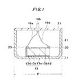
- Fig. 1 is a schematic sectional view showing an embodiment (first embodiment) having a simple construction according to the invention.
- the sectional view is taken such that the section of the piezoelectric element in the piezoelectric sensor corresponds in section to the sectional view taken along line I-I in Fig. 13. (This is applicable to the sectional views of the following embodiments.)
- Fig. 1 shows a support 31, in this instance a vessel open at the top (to be described later in detail). Also shown are a piezoelectric element 13, a securing means 15, inner leads 19a, outer leads 19b and a lid 21. The details of the components 31 and 13 to 19a and 19b are as follows.
- the piezoelectric element 13 like the one described in connection with Fig. 13, comprises a piezoelectric body 13a and electrodes 13b and 13d.
- the piezoelectric body 13a is made preferably of lead zirconate titanate (PZT).
- PZT lead zirconate titanate
- its diameter is 10 mm, and its thickness ranges from 1 to 3 mm.
- the coefficient of thermal expansion of the piezoelectric body 13a is roughly 5 x 10- 6 / O C (generally 1 x 10- s to 8 x 10- 6 / O C). Since the.piezoelectric body 13a has an illustrative thickness of 1 to 3 mm, its resonant frequency is generally in the range of 100 to 2,000 kHz.
- the electrodes 13b to 13d of the piezoelectric element 13 are made by sintering of silver paste.
- the piezoelectric bodies used in this first embodiment as well as the following embodiments and comparative examples are obtained by weighing, mixing and sintering a materials in the same steps and in well-known methods.
- the vessel 31 is made of a material having a coefficient of thermal expansion equal to or near that of the piezoelectric body material.
- it is made of an alloy of iron (Fe) and nickel (Ni) (containing 42 % by weight of Ni).
- Its outer size i.e., dimension shown at P in Fig. 1) is set preferably to 13 and 14 mm, and the thickness t of its bottom (see Fig. 1) is set preferably to 0.4 and 0.5 mm.
- the alloy has a thermal expansion coefficient of 5 x 10- 6 / o C, which is substantially equal to that of the piezoelectric body 13a.
- the preferred securing means 15 is an epoxy type adhesive with a thermal expansion coefficient of 6 x 10- 5 / O C.
- this illustrative material is by no means limitative, and it is possible to use any suitable material depending on the design.
- the inner leads 19a are formed as a strand of three wires each illustratively 0.1 mm in diameter, the strand having a diameter illustratively of 0.2 mm (which is a conventional strand).
- the outer lead 19b is a shielded wire with a core wire diameter of 0.6 mm illustratively. It has one end secured in a suitable way to the lid 21.
- piezoelectric element 13 is secured by adhesive 15 to the inner bottom surface of vessel 31. Then the inner leads 19a are connected to the first electrode 13b of the piezoelectric element 13 and the led-out portion 13d of the second electrode 13c by using connecting means 23 (for instance, by soldering with solder 23). Then the other ends of the inner leads 19a are soldered to the outer wiring 19b, and then the lid 21 is assembled. In this way, the first embodiment of the piezoelectric sensor is obtained.
- the first embodiment of the piezoelectric sensor is secured by a predetermined method of securing to a vibration system (not shown) which generates vibrations at a predetermined frequency, and then the vibration system and the piezoelectric sensor are put into a variable temperature trough (not shown) which is capable of temperature variation. Then, the temperature in the variable temperature trough is set to a plurality of different temperatures in a range of -40 to +150 ° C including a temperature of 20°C, and the output from the piezoelectric sensor is measured at each of these temperatures. This measurement is hereinafter referred to as "sensitivity-temperature characteristic measurement". The output value at each preset temperature is converted into a change rate with respect to the output at 20°C.
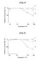
- the sensitivity-temperature characteristic measurement change rate of the first embodiment of the piezoelectric sensor was -5% at -40°C, -10% at + 100°C and -15% at +150 ° C. Similar characteristics could be obtained with samples which were obtained by changing the thickness of the bottom of the vessel 31 and the outer dimensions thereof.
- Fig. 4 shows the sensitivity-temperature characteristics of the first embodiment of the piezoelectric sensor by a curve I, with the ordinate showing the sensitivity change rate and the abscissa showing the temperature.
- Figure 4 also shows the characteristics of the following Comparative Example 1 and second, third and fourth embodiments.
- the second embodiment of the piezoelectric sensor was produced in the same way as in the first embodiment except that "Kovar” (an alloy composed of 54 wt. % of iron, 29 wt. % of nickel and 17 wt. % of cobalt) was used as the material of the vessel 31, and its sensitivity-temperature characteristic was measured in the same manner as in the first embodiment.
- the thermal expansion coefficient of "Kovar” is 5.3 x 10- 6 / o C, which is substantially equal to that of the alloy in the first embodiment.
- a lower member 33 is provided in a third embodiment.
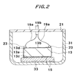
- Fig. 2 shows the third embodiment.
- the third embodiment of the piezoelectric sensor is the same in structure as the previous first embodiment except that an aluminum oxide plate with a thickness of 0.3 to 0.8 mm and a diameter of about 12 mm is interposed as lower member 33 between vessel 31 and piezoelectric element 13.
- the epoxy type adhesive 15 as noted above is used as means for securing the alumina plate 33 to the vessel 31 and means for securing the piezoelectric element 13 to the alumina plate 33.
- the coefficient of thermal expansion of the alumina plate 33 is 8 x 10- 6 / o C.
- the sensitivity-temperature characteristic of the third embodiment of the piezoelectric sensor was measured.
- the sensitivity-temperature characteristic change rate of the third embodiment of the piezoelectric sensor was 0% at -40°C, 0% at +100 ° C and -5% at +150 ° C. Similar characteristics were obtained with samples obtained by changing the thickness of the lower member 33.
- Fig. 4 shows the sensitivity-temperature characteristic of the samples of the third embodiment by a curve II as well as the first embodiment.
- Fig. 3 is a sectional view for explaining the fourth embodiment of the piezoelectric sensor.
- vessel 31 as the support has a portion 31a, which faces piezoelectric element 13, made of the Fe-Ni alloy noted above, while the other portion 17 (which is also referred to as "thermal expansion coefficient consideration-free portion") is made of iron.
- the structure is the same as the third embodiment.
- Such a special vessel is obtained by removing a bottom portion of comparative example vessel and bonding a separately prepared disk of Fe-Ni alloy noted above to the vessel such as to occupy the space produced by the removal.
- the sensitivity-temperature characteristic of the fourth embodiment of the piezoelectric sensor was found to be the same as that of the third embodiment.
- each piezoelectric sensor was produced in the same way as in the first embodiment except that iron (i.e., two samples obtained by hot and cold rolling, respectively), aluminum and bronze are each used as the material of vessel 31, and as in the first embodiment the sensitivity-temperature characteristic measurement is done.
- the coefficient of thermal expansion of each of the materials used in this comparative example is 1.2 x 10⁻⁵/°C with the hot rolled iron, roughly the same as that of the hot rolled iron with the cold rolled iron, 2.4 x 10- 5 / O C with aluminum, and 1.8 x 10- 5 / O C with bronze. In either case, the thermal expansion coefficient is less by at least one order of magnitude than that of the piezoelectric body (PZT) used.
- the sensitivity-temperature characteristic change rate of a typical piezoelectric sensor with the vessel thereof made of the cold rolled iron in the comparative example was - 7% at -40°C, -30% at +100 ° C and -50% at +150 ° C.
- Fig. 4 shows this characteristic by a curve III. It was found that the sensitivity-temperature characteristics of the piezoelectric sensors of the other comparative examples were substantially the same when the vessel was made of cold rolled iron.
- the sensitivity-temperature characteristic can be improved over to the other arrangements. Further, among the embodiments, the sensitivity-temperature characteristic can be improved by using the lower member.
- the characteristic improvement obtainable by the use of the lower member may be caused by such as substantial increase of the thickness of the support produced as a lamination of layers of different materials.
- FIG. 5 shows a top view, a side view and a bottom view for explaining the upper member that is used.
- Fig. 6 shows a top view, a side view and a bottom view for explaining a different example of the upper member.
- Fig. 7(A) is a sectional view showing the fifth embodiment of the piezoelectric sensor using the upper member shown in Fig. 5.
- Fig. 7(B) is a view showing outer wiring 37 in detail.
- Fig. 8 is a sectional view showing the fifth embodiment of the piezoelectric sensor using the upper member shown in Fig. 6.
- the upper member 35 in either case comprises an alumina plate 35a, which has a diameter of about 12 mm and a thickness of 3 mm, and electrodes 35b and 35c provided on the front and back sides of the alumina plate such as to correspond to a first and a second electrode 13b and 13c of piezoelectric element 13.
- alumina plate 35a is formed with or includes through holes 35d, and the electrodes 35b and 35c are provided therethrough.
- the example of Fig. 5 concerns a general through hole wiring structure with a space formed along the axis of each through hole 35d. However, it is possible to fill the through hole 35d with the material of the electrode 35b (or35c).
- the electrodes 35b and 35c such that they extend along and across the alumina plate 35a.
- the outer wiring 37 is a sealed wire 37 comprising an inner conductor (core wire) 37a, an outer conductor 37b, an insulator 37c insulating the inner and outer conductors, and a cover (i.e., insulator) 37d covering the outer conductor 37b.
- inner conductor 37a has a diameter of 0.6 mm
- outer conductor 37b has a diameter of 1.4 mm
- the diameter of the wiring 37 is 2 mm.
- the outer wiring 37 is sufficiently thick compared to the inner leads 19a used in the first to fourth embodiments and comparative example.
- the lower member 33 is secured with the epoxy type adhesive 15 noted above to the vessel 31.
- the piezoelectric element 13 is then secured with the epoxy type adhesive 15 to the lower member 33.
- the upper member 35 noted above is then secured to the piezoelectric element 13 by soldering the piezoelectric element side electrodes and the electrodes on the side of the upper member 35 with solder 23.
- a space or separation region 39 is formed between the piezoelectric element 13 and upper member 35 due to the connections of the electrodes.
- the inner and outer conductors 37a and 37b of the outer wiring 37 are connected, by soldering for instance, to the electrode portions of the upper member 35 on the side thereof opposite the piezoelectric element 13.
- the space in the vessel other than those occupied by the piezoelectric element and so forth is filled with silicone rubber type resin with a thermal expansion coefficient of 2 x 10⁻⁴/OC, thus sealing the piezoelectric element and so forth.
- silicone rubber type resin with a thermal expansion coefficient of 2 x 10⁻⁴/OC
- the resin laterally enters the space 39 between the piezoelectric element 13 and upper member 25, and thus the space 39 is fully or partly filled with the resin.
- the sensitivity-temperature characteristic of each piezoelectric sensor of the fifth embodiment is measured.
- the sensitivity-temperature characteristic change rate of the piezoelectric sensors in the fifth embodiment was -5% at -40°C, -10% at +100 ° C and -20% at +150 ° C.
- This characteristic is shown in Fig. 9 by a curve IV in the same manner as in Fig. 4.
- Fig. 9 also shows the characteristics of the following sixth embodiment and Comparative Example 2.
- the characteristic of the fifth embodiment is inferior to those of the first to fourth embodiments. This is thought to be due to the contact of the sealing resin mainly with the periphery of the piezoelectric element.
- This embodiment involves using an upper member, using no inner leads, and resin sealing the piezoelectric element part and so forth (but avoiding direct contact of resin with the piezoelectric element).
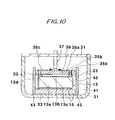
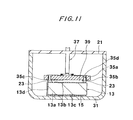
- Fig. 10 is a sectional view for explaining the sixth embodiment of the piezoelectric sensor.
- a resin tube capable of thermal shrinkage is disposed as a cover member43 to surround the entire periphery of the lamination or arrangement comprising the lower member 33, piezoelectric element 13 and upper member 35, thus forming a sealed space around the piezoelectric element.
- the resin is introduced as in the fifth embodiment, thus obtaining the sixth embodiment of the piezoelectric sensor.
- the thermally shrinkable tube is used "Sumi- tube" (a trade name by Sumitomo Denki Kogyo).
- the lower and upper members 33 and 35 have greater plan dimensions than those of the piezoelectric element 13.
- the thermally shrinkable tube is fitted on the lowerand upper members 33 and 35 with a space or separation region 45 formed around the piezoelectric element (as shown in Fig. 10).
- the space 39 between the piezoelectric element 13 and upper member 35 is preserved.
- a piezoelectric sensor is obtained in which the piezoelectric element 13 is covered by the sealing material 41 with spaces held adjacent the top surface and periphery of the piezoelectric element 13, and in which the support structure for the piezoelectric element is made of a material having a predetermined coefficient of thermal expansion.
- the sensitivity-temperature characteristic of the sixth embodiment was measured.
- the sensitivity-temperature characteristic change rate of the sixth embodiment of the piezoelectric sensor was 0% at -40°C, 0% at +100 ° C and -3% at +150 ° C.
- the characteristic is shown in Fig. 9 as a curve V.
- the piezoelectric sensor is obtained such that it has the structure in Comparative Example 1 except that the piezoelectric element is sealed in the vessel thereof by charging the resin used in the fifth and sixth embodiments.
- the sensitivity-temperature characteristic of Comparative Example 2 is measured.
- the sensitivity-temperature characteristic of Comparative Example 2 of the piezoelectric sensor is -8% at -40°C, -50% at +100 ° C and -70% at +150 ° C. This characteristic is shown in Fig. 9 by a curve VI.
- the structure of the sixth embodiment has the best characteristic among the above embodiments and comparative examples.
- upper member 35 may be incorporated in the structure of the first embodiment (see Fig. 1), and electric wire 37 having a greater diameter than in the prior art may be used.
- electric wire 37 having a greater diameter than in the prior art.
- the characteristic will be obviously improved compared to the prior art.
- the structure of the fifth embodiment see Fig. 7 or 8, except that the resin sealing is not made, will obviously provide an improved characteristic compared to the prior art.
- the shape, size and material of the piezoelectric element are not limited to those mentioned above but may be suitably selected in accordance with the design.
- other shapes and dimensions are detailed in, for instance, "Technical Information Piezoelectric Ceramics", February 20,1988, Third Edition, Oki Ceramic Kogyo Kabushiki Kaisha.
- liquid crystals and the like as the piezoelectric material.
- the material of the support may be selected in correspondence to the coefficient of thermal expansion of the piezoelectric material.
- the piezoelectric sensor according to the invention the stress generated due to the difference of the coefficient of thermal expansion between the support in contact with the piezoelectric element and the piezoelectric body can be reduced in comparison to that in the prior art. It is thus possible to improve the temperature dependency of the sensitivity of the piezoelectric sensor compared to the prior art. Further, in applications of the sensor in environments subject to great temperature changes, there is no need of using any special protector, and thus it is possible to avoid sensor size increase.
- the stress from above the piezoelectric element is substantially blocked or relieved by the upper member, and thus it is possible to provide reinforcement of the outer wiring (for instance with electric wire having a large diameter or a printed circuit board). It is thus possible to improve the durability of the sensor.
- the piezoelectric element is covered with a space or separation provided adjacent it, and the piezoelectric element is sealed with a sealing material, it is possible to mold the piezoelectric element with a space or separation held adjacent the top surface and periphery of the piezoelectric element. It is thus possible to shield the piezoelectric element from the working environment in a state with reduced adverse effects of the sealing material on the piezoelectric element. Thus, it is possible to provide a piezoelectric sensor which can be used with satisfactory durability even in severe environments.
Applications Claiming Priority (2)
| Application Number | Priority Date | Filing Date | Title |
|---|---|---|---|
| JP279660/92 | 1992-10-19 | ||
| JP27966092A JP3238492B2 (ja) | 1992-10-19 | 1992-10-19 | 圧電センサ |
Publications (2)
| Publication Number | Publication Date |
|---|---|
| EP0594331A1 true EP0594331A1 (fr) | 1994-04-27 |
| EP0594331B1 EP0594331B1 (fr) | 1997-05-07 |
Family
ID=17614088
Family Applications (1)
| Application Number | Title | Priority Date | Filing Date |
|---|---|---|---|
| EP93308001A Expired - Lifetime EP0594331B1 (fr) | 1992-10-19 | 1993-10-07 | Capteur piézo-électrique |
Country Status (5)
| Country | Link |
|---|---|
| US (1) | US5376860A (fr) |
| EP (1) | EP0594331B1 (fr) |
| JP (1) | JP3238492B2 (fr) |
| CA (1) | CA2107874C (fr) |
| DE (1) | DE69310474T2 (fr) |
Cited By (4)
| Publication number | Priority date | Publication date | Assignee | Title |
|---|---|---|---|---|
| EP0825799A2 (fr) * | 1996-08-13 | 1998-02-25 | Murata Manufacturing Co., Ltd. | Transducteur électroacoustique avec dimensions réduites et borne améliorée |
| US5987992A (en) * | 1997-03-07 | 1999-11-23 | Murata Manufacturing Co., Ltd. | Ultrasonic sensor with temperature compensation capacitor |
| WO2001045081A1 (fr) * | 1999-12-17 | 2001-06-21 | Siemens Aktiengesellschaft | Transducteur a ultrasons piezoelectrique comportant un boitier et une couche isolante |
| WO2017089609A3 (fr) * | 2015-11-26 | 2017-09-28 | Elmos Semiconductor Aktiengesellschaft | Élément oscillant pour un transducteur ultrasonore à résonance multiple |
Families Citing this family (31)
| Publication number | Priority date | Publication date | Assignee | Title |
|---|---|---|---|---|
| JPH07221590A (ja) * | 1994-01-31 | 1995-08-18 | Matsushita Electric Ind Co Ltd | 電子部品とその製造方法 |
| EP0824675B1 (fr) * | 1995-04-28 | 2003-07-09 | Rosemount Inc. | Transmetteur de pression pourvu d'un ensemble de montage isolant haute pression |
| JP3447300B2 (ja) * | 1995-04-28 | 2003-09-16 | ローズマウント インコーポレイテッド | 圧力送信機のマウント組立体 |
| US6653760B1 (en) | 1996-05-09 | 2003-11-25 | Crest Ultrasonics Corporation | Ultrasonic transducer using third harmonic frequency |
| JP3812917B2 (ja) * | 1997-05-14 | 2006-08-23 | 本田技研工業株式会社 | 圧電型アクチュエーター |
| JPH1120729A (ja) * | 1997-07-02 | 1999-01-26 | Toyota Autom Loom Works Ltd | 車両におけるセンサの取付構造 |
| US6313568B1 (en) | 1999-12-01 | 2001-11-06 | Cummins Inc. | Piezoelectric actuator and valve assembly with thermal expansion compensation |
| DE10017760C1 (de) * | 2000-04-10 | 2001-08-16 | Festo Ag & Co | Piezokeramischer Biegewandler sowie Verwendung des piezokeramischen Biegewandlers |
| US6570298B2 (en) * | 2000-05-09 | 2003-05-27 | Tokkyokiki Co., Ltd. | Vibration control device and driving method thereof |
| DE10023556A1 (de) * | 2000-05-15 | 2001-11-29 | Festo Ag & Co | Piezo-Biegewandler sowie Verwendung desselben |
| DE20202297U1 (de) * | 2001-09-07 | 2002-08-29 | Drei S Werk Praez Swerkzeuge G | Flacher Aktor oder Sensor mit interner Vorspannung |
| US7259500B2 (en) * | 2004-07-14 | 2007-08-21 | Murata Manufacturing Co., Ltd. | Piezoelectric device |
| JP2006105964A (ja) * | 2004-09-13 | 2006-04-20 | Denso Corp | 圧電センサ |
| JP5089860B2 (ja) * | 2004-12-03 | 2012-12-05 | 富士フイルム株式会社 | 圧電アクチュエータ及び液体吐出ヘッド |
| US7462977B2 (en) * | 2005-04-07 | 2008-12-09 | Kulite Semiconductor Products, Inc | High temperature pressure transducer having a shaped ceramic face |
| JP4301298B2 (ja) * | 2007-01-29 | 2009-07-22 | 株式会社デンソー | 超音波センサ及び超音波センサの製造方法 |
| JP4983282B2 (ja) * | 2007-02-07 | 2012-07-25 | パナソニック株式会社 | 音響整合部材 |
| US9406314B1 (en) | 2012-10-04 | 2016-08-02 | Magnecomp Corporation | Assembly of DSA suspensions using microactuators with partially cured adhesive, and DSA suspensions having PZTs with wrap-around electrodes |
| US8773820B1 (en) | 2013-02-21 | 2014-07-08 | Magnecomp Corporation | PZT microactuator for disk drive suspension having electrical via and wrap-around electrode |
| US9322720B2 (en) * | 2013-02-25 | 2016-04-26 | U.S. Department Of Energy | Use of aluminum nitride to obtain temperature measurements in a high temperature and high radiation environment |
| US9741376B1 (en) | 2013-03-18 | 2017-08-22 | Magnecomp Corporation | Multi-layer PZT microactuator having a poled but inactive PZT constraining layer |
| US9330698B1 (en) | 2013-03-18 | 2016-05-03 | Magnecomp Corporation | DSA suspension having multi-layer PZT microactuator with active PZT constraining layers |
| US11205449B2 (en) | 2013-03-18 | 2021-12-21 | Magnecomp Corporation | Multi-layer PZT microacuator with active PZT constraining layers for a DSA suspension |
| US10607642B2 (en) | 2013-03-18 | 2020-03-31 | Magnecomp Corporation | Multi-layer PZT microactuator with active PZT constraining layers for a DSA suspension |
| US9070394B1 (en) | 2013-03-18 | 2015-06-30 | Magnecomp Corporation | Suspension microactuator with wrap-around electrode on inactive constraining layer |
| US9117468B1 (en) | 2013-03-18 | 2015-08-25 | Magnecomp Corporation | Hard drive suspension microactuator with restraining layer for control of bending |
| US9330694B1 (en) | 2013-03-18 | 2016-05-03 | Magnecomp Corporation | HDD microactuator having reverse poling and active restraining layer |
| US10128431B1 (en) | 2015-06-20 | 2018-11-13 | Magnecomp Corporation | Method of manufacturing a multi-layer PZT microactuator using wafer-level processing |
| RU2684139C1 (ru) * | 2018-06-14 | 2019-04-04 | Российская Федерация, от имени которой выступает Государственная корпорация по атомной энергии "Росатом" (Госкорпорация "Росатом") | Пьезоэлектрический датчик |
| TWI707146B (zh) * | 2019-06-12 | 2020-10-11 | 千竣科技有限公司 | 超聲波偵測裝置 |
| JP2021057751A (ja) * | 2019-09-30 | 2021-04-08 | セイコーエプソン株式会社 | 超音波装置、及び超音波装置の製造方法 |
Citations (3)
| Publication number | Priority date | Publication date | Assignee | Title |
|---|---|---|---|---|
| JPS55135718A (en) * | 1979-04-10 | 1980-10-22 | Nissan Motor Co Ltd | Oscillation sensor |
| US4462247A (en) * | 1981-03-06 | 1984-07-31 | Nippon Soken, Inc. | Knock detecting apparatus for internal combustion engines |
| US4672839A (en) * | 1984-11-27 | 1987-06-16 | Ngk Spark Plug Co., Ltd. | Vibration sensor |
Family Cites Families (9)
| Publication number | Priority date | Publication date | Assignee | Title |
|---|---|---|---|---|
| CH429228A (de) * | 1964-12-10 | 1967-01-31 | Kistler Instrumente Ag | Piezoelektrischer Einbaukörper zum Einbau in einen piezoelektrischen Wandler |
| US3441754A (en) * | 1966-05-31 | 1969-04-29 | Linden Lab Inc | Base mounted piezoelectric transducer assembly having intermediate stress absorbing member |
| US3624264A (en) * | 1970-02-18 | 1971-11-30 | Arnold Lazarus | Method and apparatus for sound and vibration detection |
| CH528178A (de) * | 1970-08-14 | 1972-09-15 | Siemens Ag | Halterung für einen stabförmigen Quarzvibrator |
| US3935484A (en) * | 1974-02-25 | 1976-01-27 | Westinghouse Electric Corporation | Replaceable acoustic transducer assembly |
| US4551647A (en) * | 1983-03-08 | 1985-11-05 | General Electric Company | Temperature compensated piezoelectric transducer and lens assembly and method of making the assembly |
| GB2155732B (en) * | 1984-03-14 | 1987-05-28 | Rolls Royce | Stress wave transducer |
| US5038069A (en) * | 1987-11-09 | 1991-08-06 | Texas Instruments Incorporated | Cylinder pressure sensor for an internal combustion engine |
| US4825117A (en) * | 1987-11-27 | 1989-04-25 | General Electric Company | Temperature compensated piezoelectric transducer assembly |
-
1992
- 1992-10-19 JP JP27966092A patent/JP3238492B2/ja not_active Expired - Lifetime
-
1993
- 1993-10-06 CA CA002107874A patent/CA2107874C/fr not_active Expired - Fee Related
- 1993-10-07 EP EP93308001A patent/EP0594331B1/fr not_active Expired - Lifetime
- 1993-10-07 DE DE69310474T patent/DE69310474T2/de not_active Expired - Lifetime
- 1993-10-12 US US08/135,433 patent/US5376860A/en not_active Expired - Lifetime
Patent Citations (3)
| Publication number | Priority date | Publication date | Assignee | Title |
|---|---|---|---|---|
| JPS55135718A (en) * | 1979-04-10 | 1980-10-22 | Nissan Motor Co Ltd | Oscillation sensor |
| US4462247A (en) * | 1981-03-06 | 1984-07-31 | Nippon Soken, Inc. | Knock detecting apparatus for internal combustion engines |
| US4672839A (en) * | 1984-11-27 | 1987-06-16 | Ngk Spark Plug Co., Ltd. | Vibration sensor |
Non-Patent Citations (1)
| Title |
|---|
| PATENT ABSTRACTS OF JAPAN vol. 5, no. 5 (P - 44) 14 January 1981 (1981-01-14) * |
Cited By (6)
| Publication number | Priority date | Publication date | Assignee | Title |
|---|---|---|---|---|
| EP0825799A2 (fr) * | 1996-08-13 | 1998-02-25 | Murata Manufacturing Co., Ltd. | Transducteur électroacoustique avec dimensions réduites et borne améliorée |
| EP0825799A3 (fr) * | 1996-08-13 | 2005-03-09 | Murata Manufacturing Co., Ltd. | Transducteur électroacoustique avec dimensions réduites et borne améliorée |
| US5987992A (en) * | 1997-03-07 | 1999-11-23 | Murata Manufacturing Co., Ltd. | Ultrasonic sensor with temperature compensation capacitor |
| DE19808994C2 (de) * | 1997-03-07 | 2002-05-29 | Murata Manufacturing Co | Ultraschallsensor mit Temperaturkompensationskondensator |
| WO2001045081A1 (fr) * | 1999-12-17 | 2001-06-21 | Siemens Aktiengesellschaft | Transducteur a ultrasons piezoelectrique comportant un boitier et une couche isolante |
| WO2017089609A3 (fr) * | 2015-11-26 | 2017-09-28 | Elmos Semiconductor Aktiengesellschaft | Élément oscillant pour un transducteur ultrasonore à résonance multiple |
Also Published As
| Publication number | Publication date |
|---|---|
| JP3238492B2 (ja) | 2001-12-17 |
| JPH06133397A (ja) | 1994-05-13 |
| US5376860A (en) | 1994-12-27 |
| DE69310474D1 (de) | 1997-06-12 |
| DE69310474T2 (de) | 1997-08-21 |
| EP0594331B1 (fr) | 1997-05-07 |
| CA2107874A1 (fr) | 1994-04-20 |
| CA2107874C (fr) | 1999-03-23 |
Similar Documents
| Publication | Publication Date | Title |
|---|---|---|
| EP0594331B1 (fr) | Capteur piézo-électrique | |
| US8080925B2 (en) | Inertial sensor with dual cavity package and method of fabrication | |
| US4236832A (en) | Strain insensitive integrated circuit resistor pair | |
| DE19727214C2 (de) | Halbleiterbeschleunigungssensor, insb. für Airbags | |
| US5635649A (en) | Multi-function differential pressure sensor with thin supporting base | |
| EP0552017B1 (fr) | Capteur de pression à semi-conducteurs et son procédé de fabrication | |
| KR0165517B1 (ko) | 진동 검출 센서 | |
| EP0722218B1 (fr) | Dispositif à ondes acoustiques de surface | |
| EP0646799B1 (fr) | Capteur d'accélération | |
| US20010011857A1 (en) | Surface acoustic wave device and method for fabricating the same | |
| US4531267A (en) | Method for forming a pressure sensor | |
| JPS58182285A (ja) | 圧電気圧力センサ | |
| US4080830A (en) | Pressure transducer | |
| US11747361B2 (en) | Acceleration transducer | |
| US11668728B2 (en) | Acceleration transducer | |
| US20220137086A1 (en) | Acceleration transducer | |
| US3541478A (en) | Electrical filter body construction having deposited outer surface | |
| US5323639A (en) | Vibration sensor | |
| US4441370A (en) | Vibration sensor | |
| JPH08320341A (ja) | 力学量検出装置 | |
| EP0511762B1 (fr) | Détecteur piézoélectrique | |
| JPS62140038A (ja) | 圧力検出器 | |
| JP3550458B2 (ja) | 静電容量式の気体用圧力センサ | |
| CA1317480C (fr) | Terminal d'entree/sortie pour transducteurs de pression a flexion | |
| KR970000779B1 (ko) | 반도체 압력센서 및 그 제조방법 |
Legal Events
| Date | Code | Title | Description |
|---|---|---|---|
| PUAI | Public reference made under article 153(3) epc to a published international application that has entered the european phase |
Free format text: ORIGINAL CODE: 0009012 |
|
| AK | Designated contracting states |
Kind code of ref document: A1 Designated state(s): DE GB IT |
|
| 17P | Request for examination filed |
Effective date: 19941007 |
|
| 17Q | First examination report despatched |
Effective date: 19960322 |
|
| GRAG | Despatch of communication of intention to grant |
Free format text: ORIGINAL CODE: EPIDOS AGRA |
|
| GRAH | Despatch of communication of intention to grant a patent |
Free format text: ORIGINAL CODE: EPIDOS IGRA |
|
| GRAH | Despatch of communication of intention to grant a patent |
Free format text: ORIGINAL CODE: EPIDOS IGRA |
|
| GRAA | (expected) grant |
Free format text: ORIGINAL CODE: 0009210 |
|
| AK | Designated contracting states |
Kind code of ref document: B1 Designated state(s): DE GB IT |
|
| PG25 | Lapsed in a contracting state [announced via postgrant information from national office to epo] |
Ref country code: IT Free format text: LAPSE BECAUSE OF FAILURE TO SUBMIT A TRANSLATION OF THE DESCRIPTION OR TO PAY THE FEE WITHIN THE PRESCRIBED TIME-LIMIT;WARNING: LAPSES OF ITALIAN PATENTS WITH EFFECTIVE DATE BEFORE 2007 MAY HAVE OCCURRED AT ANY TIME BEFORE 2007. THE CORRECT EFFECTIVE DATE MAY BE DIFFERENT FROM THE ONE RECORDED. Effective date: 19970507 |
|
| REF | Corresponds to: |
Ref document number: 69310474 Country of ref document: DE Date of ref document: 19970612 |
|
| PLBE | No opposition filed within time limit |
Free format text: ORIGINAL CODE: 0009261 |
|
| STAA | Information on the status of an ep patent application or granted ep patent |
Free format text: STATUS: NO OPPOSITION FILED WITHIN TIME LIMIT |
|
| 26N | No opposition filed | ||
| REG | Reference to a national code |
Ref country code: GB Ref legal event code: 732E |
|
| REG | Reference to a national code |
Ref country code: GB Ref legal event code: IF02 |
|
| REG | Reference to a national code |
Ref country code: GB Ref legal event code: 732E |
|
| PGFP | Annual fee paid to national office [announced via postgrant information from national office to epo] |
Ref country code: GB Payment date: 20101018 Year of fee payment: 18 |
|
| PGFP | Annual fee paid to national office [announced via postgrant information from national office to epo] |
Ref country code: DE Payment date: 20101229 Year of fee payment: 18 |
|
| GBPC | Gb: european patent ceased through non-payment of renewal fee |
Effective date: 20111007 |
|
| PG25 | Lapsed in a contracting state [announced via postgrant information from national office to epo] |
Ref country code: DE Free format text: LAPSE BECAUSE OF NON-PAYMENT OF DUE FEES Effective date: 20120501 |
|
| REG | Reference to a national code |
Ref country code: DE Ref legal event code: R119 Ref document number: 69310474 Country of ref document: DE Effective date: 20120501 |
|
| PG25 | Lapsed in a contracting state [announced via postgrant information from national office to epo] |
Ref country code: GB Free format text: LAPSE BECAUSE OF NON-PAYMENT OF DUE FEES Effective date: 20111007 |