EP0594055B1 - Couvercle pour tête d'impression d'une imprimante par jet d'encre - Google Patents
Couvercle pour tête d'impression d'une imprimante par jet d'encre Download PDFInfo
- Publication number
- EP0594055B1 EP0594055B1 EP93116598A EP93116598A EP0594055B1 EP 0594055 B1 EP0594055 B1 EP 0594055B1 EP 93116598 A EP93116598 A EP 93116598A EP 93116598 A EP93116598 A EP 93116598A EP 0594055 B1 EP0594055 B1 EP 0594055B1
- Authority
- EP
- European Patent Office
- Prior art keywords
- print head
- filling
- lid according
- cover
- ink
- Prior art date
- Legal status (The legal status is an assumption and is not a legal conclusion. Google has not performed a legal analysis and makes no representation as to the accuracy of the status listed.)
- Expired - Lifetime
Links
Images
Classifications
-
- B—PERFORMING OPERATIONS; TRANSPORTING
- B41—PRINTING; LINING MACHINES; TYPEWRITERS; STAMPS
- B41J—TYPEWRITERS; SELECTIVE PRINTING MECHANISMS, i.e. MECHANISMS PRINTING OTHERWISE THAN FROM A FORME; CORRECTION OF TYPOGRAPHICAL ERRORS
- B41J2/00—Typewriters or selective printing mechanisms characterised by the printing or marking process for which they are designed
- B41J2/005—Typewriters or selective printing mechanisms characterised by the printing or marking process for which they are designed characterised by bringing liquid or particles selectively into contact with a printing material
- B41J2/01—Ink jet
- B41J2/17—Ink jet characterised by ink handling
- B41J2/175—Ink supply systems ; Circuit parts therefor
- B41J2/17503—Ink cartridges
- B41J2/17513—Inner structure
-
- B—PERFORMING OPERATIONS; TRANSPORTING
- B41—PRINTING; LINING MACHINES; TYPEWRITERS; STAMPS
- B41J—TYPEWRITERS; SELECTIVE PRINTING MECHANISMS, i.e. MECHANISMS PRINTING OTHERWISE THAN FROM A FORME; CORRECTION OF TYPOGRAPHICAL ERRORS
- B41J2/00—Typewriters or selective printing mechanisms characterised by the printing or marking process for which they are designed
- B41J2/005—Typewriters or selective printing mechanisms characterised by the printing or marking process for which they are designed characterised by bringing liquid or particles selectively into contact with a printing material
- B41J2/01—Ink jet
- B41J2/17—Ink jet characterised by ink handling
- B41J2/175—Ink supply systems ; Circuit parts therefor
- B41J2/17503—Ink cartridges
- B41J2/17506—Refilling of the cartridge
Definitions
- the invention relates to a cover for a print head of an ink jet printer according to the preamble of claim 1. It also relates to a print head of an ink jet printer according to the preamble of claim 11.
- Printheads such as are commercially available today, receive the ink supply in an ink supply chamber arranged within a housing, in which the foamed material that often receives the ink is located. It is preferably polyurethane foam of defined porosity and capillarity, which is particularly suitable for the absorption of ink.
- a single ink supply chamber is provided; the print head for a multicolor printer generally contains three separate ink supply chambers for holding three different color components, for example magenta, cyan and yellow.
- the ink supply chambers are above from above a filling hole accessible.
- the chambers are closed at the top by a common cover plate which has three through holes arranged in a line. The through holes are used to fill the printhead with the required supply of ink at the factory. After the filling process has ended, a cover is generally applied which covers the entire surface of the housing of the print head.
- the lid has a raised section that can rise from the base in the manner of a cuboid. This simplifies the handling of the printhead, since the other housing parts are not suitable as a gripping surface, because they sometimes contain functional elements that must not be touched, e.g. the contact film for electrical connection to the control device or the nozzle plate, or because they are not sufficiently accessible due to guide surfaces or other components provided on the printer.
- the lid also usually contains markings, e.g. in the form of an arrow, which make it easier to insert the printhead correctly.
- the present invention was based on the problem of providing a cover for a printhead of an ink jet printer of the type mentioned at the outset, which eliminates these disadvantages. In particular, it should allow access to the filling holes and thus to the ink supply chambers themselves in a simple manner.
- the invention is based on the idea of providing the lid as such with filling openings which communicate with the filling bores of the printhead.
- the number of filling openings corresponds to the number of ink chambers, so that each filling opening is assigned to a specific filling hole. This makes it possible to easily add ink supply without having to remove the cover from the housing of the print head. Ink can be replenished in a targeted manner by simple means, such as an injection needle. This is particularly advantageous in the case of a multicolor printhead, since it is sufficient for the color component used in each case refill individually.
- the lid is made of a transparent material. This makes it possible to observe the refilling process and thus largely rule out errors. It can thus be seen immediately which fill opening in the lid of the respective filling hole of the ink supply chamber and thus is assigned to a specific color component of the ink.
- the filling openings which are located on the raised shaped handling section of the lid, can be connected in a sealing manner to the respective filling openings via tubular, continuous channels.
- in the event of accidental overfilling it is not possible for ink to pass into an adjacent ink supply space, since the excess ink rises upwards in the tubular channel and the overfill is thereby immediately recognizable.
- the transfer of even small amounts of ink into an adjacent ink chamber must be avoided under all circumstances, since this leads to incorrect color reproduction and thus to the print head being unusable.
- the insertion of the injection needle can further be facilitated in that the filling openings are provided with a funnel-shaped countersink. It is also advantageous if the filling openings have a relatively large diameter, in which case the Cross-sectional profile of the tubular channels to the respective filling hole decreases.
- the tubular channels are designed at the lower end so that they engage sealingly in the filling holes. For this purpose, they can protrude into the filling bores, for example, overlapping in the axial direction by a certain amount.
- the cover can be attached to the printhead in various ways, ie releasably or non-releasably. As such, it is sufficient, as before, to glue the cover to the edge of the printhead housing. This is particularly useful if the print head is already equipped with such a cover when it is first delivered, that is, at the factory. On the other hand, it is particularly advantageous to detachably attach the lid, with the aid of locking elements provided on the print head side. In this way, the cover can easily be detached from the housing at the end of the print head's life and recycled.
- the particular advantage of such a configuration is that even older printheads that are already in use can be converted to refillable printheads.
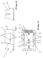
- the lid 1 has a substantially flat base plate 12 from which a handling section rises.
- the handling section 2 has a rectangular outline and extends over a large part of the base plate 12.
- the rear side 13 of the handling section 2 extends essentially perpendicular to the base plate 12.
- the front side 14 is designed to be slightly oblique, so that overall a trapezoidal cross section results.
- a marking 15 is attached, which in plan view has the shape of an arrow and rises as an integral part of the handling section 2 from the front 14 thereof.
- the arrow 15 indicates the direction in which the print head must be inserted into the printer.
- the side surfaces 9 have a shoulder 8.
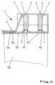
- the paragraph 8 is provided with openings 10 through which resilient locking elements 110 are passed.
- the locking elements 110 are attached to a cover plate 102 of the ink supply chambers.
- the latching elements 110 have a latching lug 112 with a latching web 111.
- the latching elements 110 slide with the front part of the latching lug 112 along the inside of the side wall 9 and are pressed inward with elastic deformation.
- the latching elements 110 Shortly before the cover 1 is placed on the housing of the print head 100, the latching elements 110 penetrate the openings 10 of the shoulder 8 until they finally snap into the end position of the cover 1.
- the locking web 111 is pressed against the lower edge 11 of the side wall 9 in the region of the opening 10.
- the locking elements 110 are in the area of the locking lug 112, in particular with respect to the extension of the locking web 111, exactly matched in the longitudinal direction to the width of the openings 10, in particular in the area of the lower edge 11, so that the cover 1 with respect to the print head 100 in the desired position is fixed.
- a web 20, which at least in sections runs around, can be formed on the underside of the cover 1 and is used for positioning on a not shown existing paragraph on the print head side is determined.
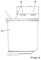
- the lid has two filling openings 3 in the area of the handling section 2 and one filling opening 4 in the area of the base plate 12. These are each assigned to filling bores 103, 104 of the ink supply chambers in the print head 100, which are not shown in detail. It is therefore a printhead for a color printer, the three separately arranged ink storage chambers of which are ink, e.g. pick up in the color components magenta, cyan and yellow.
- the filling bores 103, 104 of the printhead 100 which are located underneath, are easily and clearly accessible through the filling openings 3, 4.
- the filling bores 103, 104 are arranged in the cover plate 102, which otherwise tightly seals the ink supply chambers. Ring webs 105, 106 are formed around the filling openings 103, 104.
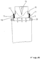
- the ring webs 105 of the filling bores 103 are used as a bearing web for tubular channels 5, which are designed as a continuous connection between the filling openings 3 and the filling bores 103 and are integrally formed on the inside of the cover 1.
- the tubular channels 5 have annular shoulder webs 7, so that they are guided into the annular webs 105 with a partial axial overlap.
- the liquid-tight transition from the channels 5 to the filling bores 103 is achieved by an exact design and dimensioning of the heel webs 7.
- the channels 5 have a cross-sectional profile that tapers from top to bottom. This makes it possible to make the filling openings 3 relatively large, so that the injection needle to be inserted for filling can be inserted easily.
- the introduction is additionally facilitated in that the filler openings 3 have insertion aids in the form of funnel-shaped countersinks 6.
- a correspondingly designed insertion aid is also attached to the filling opening 4 arranged in the area of the base plate 12.
- the separate arrangement of the filling openings 3, 4 and the fluid-tight transitions from the channels 5 to the filling bores 103 reliably prevent unintentional passage of ink into an adjacent filling bore. In the event that excess ink should pass up through one of the filling bores 103, this remains in the interior of the associated channel 5, which in this case has the function of a collection or buffer volume.
- the cover 1 is made of transparent material. In this way, it is first possible to determine the assignment of each fill opening 3, 4 to the respective ink supply chamber and thus to the respective color component. The respective color component can thus be seen at least through the filling bores 103, 104. In most cases, the recognition is facilitated by the fact that the cover plate 102 itself is made of transparent material and thus provides a view into the interior of the ink supply chambers.
- the filling process itself can also be optimally controlled. It can be seen immediately when the capacity of the ink supply chamber is exhausted and therefore ink no longer flows off in the filling bore 103, 104. This makes the refill process itself very economical, since overfilling the print head is practically impossible. Even in the case of overfilling, there is no danger that the color reproduction will be falsified by a color component which has passed into an adjacent ink supply chamber.
- cover according to the invention is particularly preferably used in print heads for multicolor printers, it can nevertheless also be used in print heads which have only a single ink supply chamber which is filled, for example, with black ink. In this case, only one fill opening has to be provided.
- the cover according to the invention can be used on the one hand for the initial equipment of a printhead.
- the print head is configured at the factory as a refillable print head.
Landscapes
- Ink Jet (AREA)
Claims (12)
- Couvercle pour tête d'impression d'une imprimante à jet d'encre, portant une calotte de saisie moulée en hauteur, la tête d'impression étant équipée d'au moins une chambre d'alimentation d'encre accessible par le haut à travers un orifice de remplissage, caractérisé en ce que des orifices d'introduction (3, 4), en nombre correspondant à celui des chambres, sont disposés de manière que chacun d'eux soit associé et en communication avec un orifice de remplissage (103, 104) de la tête d'impression (100).
- Couvercle selon la revendication 1, caractérisé en ce qu'il est réalisé en un matériau transparent.
- Couvercle selon la revendication 2, caractérisé en ce que le matériau transparent est du polystyrène.
- Couvercle selon l'une des revendications précédentes, caractérisé en ce que les orifices d'introduction (3) situés sur la calotte de saisie (2) débouchent dans des canaux tubulaires (5) conçus de manière à communiquer avec les orifices de remplissage correspondants (103).
- Couvercle selon la revendication 4, caractérisé en ce que les orifices d'introduction (3) disposés sur la calotte de saisie (2) présentent des aides à l'introduction (6).
- Couvercle selon la revendication 5, caractérisé en ce que les aides à l'introduction (6) ont la forme d'une découpe creusée en entonnoir.
- Couvercle selon l'une des revendications 4 à 6, caractérisé en ce que les canaux tubulaires (5) ont une section transversale qui va en diminuant du haut vers le bas.
- Couvercle selon l'une des revendications 4 à 7, caractérisé en ce que les canaux tubulaires (5) présentent, à leurs extrémités inférieures, chacun un collet (7) conçu pour venir en prise étanche à l'intérieur de l'orifice de remplissage correspondant (103).
- Couvercle selon une des revendications précédentes, caractérisé en ce que les parois latérales (9) présentent des découpes (10) conçues de manière que des éléments d'arrêt (110) situés du côté de la tête et déformables élastiquement puissent y être engagés et y rester maintenus par des barrettes d'arrêt (111) en appui sous tension contre le bord inférieur (11) de la découpe (10) formant surface d'arrêt.
- Couvercle selon l'une des revendications précédentes, caractérisé en ce que sa face inférieure porte un rebord moulé (20) occupant au moins une partie de la périphérie et conçu pour assurer le positionnement par appui le long d'une partie en relief située du côté de la tête.
- Tête d'impression d'une imprimante à jet d'encre équipée d'au moins une chambre d'alimentation d'encre accessible par le haut à travers un orifice de remplissage, caractérisée en ce qu'elle est équipée d'un couvercle selon l'une des revendications 1 à 10.
- Utilisation d'un couvercle selon l'une des revendications 1 à 10 pour remplacer, dans une imprimante à jet d'encre, une tête d'impression du type jetable par une tête d'impression rechargeable.
Applications Claiming Priority (2)
| Application Number | Priority Date | Filing Date | Title |
|---|---|---|---|
| DE4235029A DE4235029C2 (de) | 1992-10-19 | 1992-10-19 | Deckel für einen Druckkopf eines Tintenstrahldruckers |
| DE4235029 | 1992-10-19 |
Publications (2)
| Publication Number | Publication Date |
|---|---|
| EP0594055A1 EP0594055A1 (fr) | 1994-04-27 |
| EP0594055B1 true EP0594055B1 (fr) | 1996-03-06 |
Family
ID=6470690
Family Applications (1)
| Application Number | Title | Priority Date | Filing Date |
|---|---|---|---|
| EP93116598A Expired - Lifetime EP0594055B1 (fr) | 1992-10-19 | 1993-10-14 | Couvercle pour tête d'impression d'une imprimante par jet d'encre |
Country Status (4)
| Country | Link |
|---|---|
| EP (1) | EP0594055B1 (fr) |
| AT (1) | ATE134935T1 (fr) |
| DE (2) | DE4235029C2 (fr) |
| DK (1) | DK0594055T3 (fr) |
Families Citing this family (6)
| Publication number | Priority date | Publication date | Assignee | Title |
|---|---|---|---|---|
| JP3327046B2 (ja) * | 1995-04-21 | 2002-09-24 | セイコーエプソン株式会社 | 記録装置用インクタンクならびにインクタンクのインク補給方法 |
| US5748216A (en) * | 1991-06-19 | 1998-05-05 | Hewlett-Packard Company | Inkjet print cartridge having valve connectable to an external ink reservoir for recharging the print cartridge |
| US5675367A (en) * | 1992-12-23 | 1997-10-07 | Hewlett-Packard Company | Inkjet print cartridge having handle which incorporates an ink fill port |
| US5531055A (en) * | 1994-04-06 | 1996-07-02 | Nu-Kote International, Inc. | Refill assembly and system for ink-jet printer cartridges |
| DE4434186A1 (de) * | 1994-09-24 | 1996-03-28 | Pms Gmbh Prod & Recycling | Druckkopf für einen Tintenstrahldrucker und Vorrichtung zum Wiederbefüllen eines derartigen Druckkopfs |
| IT1283111B1 (it) | 1996-06-07 | 1998-04-07 | B M S Costruzione Stampi S R L | Dispositivo di ricarica per testina di scrittura a getto d'inchiostro |
Family Cites Families (8)
| Publication number | Priority date | Publication date | Assignee | Title |
|---|---|---|---|---|
| IT1160247B (it) * | 1983-12-27 | 1987-03-04 | Olivetti & Co Spa | Testina di stampa seriale a getto d'inchiostro elettricamente conduttivo |
| DE3401071A1 (de) * | 1984-01-13 | 1985-07-25 | Siemens AG, 1000 Berlin und 8000 München | Vorrichtung zum nachfuellen von tintenbehaeltern in tintenschreibeinrichtungen |
| US4907018A (en) * | 1988-11-21 | 1990-03-06 | Hewlett-Packard Company | Printhead-carriage alignment and electrical interconnect lock-in mechanism |
| US4931811A (en) * | 1989-01-31 | 1990-06-05 | Hewlett-Packard Company | Thermal ink jet pen having a feedtube with improved sizing and operational with a minimum of depriming |
| US4907019A (en) * | 1989-03-27 | 1990-03-06 | Tektronix, Inc. | Ink jet cartridges and ink cartridge mounting system |
| US4968998A (en) * | 1989-07-26 | 1990-11-06 | Hewlett-Packard Company | Refillable ink jet print system |
| US4935751A (en) * | 1989-09-21 | 1990-06-19 | Hewlett-Packard Company | Level sensor for ink bag |
| NL9200767A (nl) * | 1992-04-28 | 1993-11-16 | Hubertus Antonius Johannes Sme | Werkwijze en houder voor het navullen van bij inktstraaldrukinrichtingen en dergelijke te gebruiken inktpatronen. |
-
1992
- 1992-10-19 DE DE4235029A patent/DE4235029C2/de not_active Expired - Fee Related
-
1993
- 1993-10-14 DE DE59301788T patent/DE59301788D1/de not_active Expired - Fee Related
- 1993-10-14 EP EP93116598A patent/EP0594055B1/fr not_active Expired - Lifetime
- 1993-10-14 AT AT93116598T patent/ATE134935T1/de not_active IP Right Cessation
- 1993-10-14 DK DK93116598.9T patent/DK0594055T3/da active
Also Published As
| Publication number | Publication date |
|---|---|
| DE4235029A1 (de) | 1994-04-21 |
| DE59301788D1 (de) | 1996-04-11 |
| EP0594055A1 (fr) | 1994-04-27 |
| ATE134935T1 (de) | 1996-03-15 |
| DK0594055T3 (da) | 1996-05-20 |
| DE4235029C2 (de) | 1994-07-14 |
Similar Documents
| Publication | Publication Date | Title |
|---|---|---|
| DE69628687T2 (de) | Element und Verfahren zum Schützen eines Tintenbehälters | |
| DE60032274T2 (de) | Flüssigkeitsbehälter, Aufzeichnungskopf und damit versehenes Aufzeichnungsgerät | |
| DE60100995T2 (de) | Verriegelungs- und griffvorrichtung für einen austauschbaren tintenbehälter | |
| DE19534577C2 (de) | Tintenpatrone und Tintenstrahl-Aufzeichnungsgerät | |
| DE4327178C1 (de) | Vorrichtung zum Wiederbefüllen eines Druckkopfs eines Tintenstrahldruckers | |
| DE60317965T2 (de) | Kodierter Zuführungskanal zur Zufuhr von festen Tintenstiften | |
| DE60131687T2 (de) | Auswechselbarer Tintenbehälter für ein Tintenstrahldrucksystem | |
| DE60300337T2 (de) | Tintenbehälter, Aufzeichnungskopf und Aufzeichnungsgerät mit einem solchen Behälter | |
| DE10327251B4 (de) | Tintenstrahl-Aufzeichnungseinrichtung und Tintenkartusche | |
| DE69723737T2 (de) | Tintenbehälter mit elektronischen und mechanischen merkmalen, der zwischen verschiedenen versorgungsgrössen steckerkompabilität erlaubt | |
| DE60101146T2 (de) | Tintenbehälter für zuverlässige elektrische verbindung und flüssigkeitsverbindung mit einer aufnahmestation | |
| DE3401071A1 (de) | Vorrichtung zum nachfuellen von tintenbehaeltern in tintenschreibeinrichtungen | |
| DE3336815A1 (de) | Vorrichtung zur tintenzufuhr fuer tintenstrahldrucker | |
| DE19648456A1 (de) | Nachfüllvorrichtung für Tintenpatronen eines Tintenstrahldruckers, Patronenstation sowie Tintenflasche | |
| DE19609879A1 (de) | Lagerbehälter für Tintenstrahldruckeinheit | |
| CH632190A5 (de) | Austauschbare fluessigkeitsvorratspatrone eines fluessigkeitsstrahldruckers. | |
| DE10341787A1 (de) | Tintenpatrone | |
| DE19615925B4 (de) | Mit Tinte versorgter Drucker und Tintenzuführtank | |
| DE60106211T2 (de) | Tintenbehälter für zuverlässige elektrische verbindung mit einer aufnahmestation | |
| DE69637184T2 (de) | Flüssigkeitsausstossaufzeichnungsgerät | |
| DE69635532T2 (de) | Tintenpatrone | |
| EP0594055B1 (fr) | Couvercle pour tête d'impression d'une imprimante par jet d'encre | |
| DE60205471T2 (de) | Zur herstellung einer zuverlässigen fluidischen verbindung zu einer empfangsstation gestalteter tintenbehälter | |
| EP0672527A2 (fr) | Tête d'impression multicolore pour imprimante par jet d'encre | |
| DE60311349T2 (de) | Vorrichtung zum Laden und Zuführen für feste Tinte |
Legal Events
| Date | Code | Title | Description |
|---|---|---|---|
| PUAI | Public reference made under article 153(3) epc to a published international application that has entered the european phase |
Free format text: ORIGINAL CODE: 0009012 |
|
| AK | Designated contracting states |
Kind code of ref document: A1 Designated state(s): AT CH DE DK FR GB IT LI NL SE |
|
| 17P | Request for examination filed |
Effective date: 19940311 |
|
| 17Q | First examination report despatched |
Effective date: 19950626 |
|
| GRAA | (expected) grant |
Free format text: ORIGINAL CODE: 0009210 |
|
| AK | Designated contracting states |
Kind code of ref document: B1 Designated state(s): AT CH DE DK FR GB IT LI NL SE |
|
| REF | Corresponds to: |
Ref document number: 134935 Country of ref document: AT Date of ref document: 19960315 Kind code of ref document: T |
|
| REG | Reference to a national code |
Ref country code: CH Ref legal event code: NV Representative=s name: DIPL.-ING. ETH H. R. WERFFELI PATENTANWALT |
|
| ET | Fr: translation filed | ||
| GBT | Gb: translation of ep patent filed (gb section 77(6)(a)/1977) |
Effective date: 19960311 |
|
| REF | Corresponds to: |
Ref document number: 59301788 Country of ref document: DE Date of ref document: 19960411 |
|
| ITF | It: translation for a ep patent filed |
Owner name: FIAMMENGHI - DOMENIGHETTI |
|
| REG | Reference to a national code |
Ref country code: DK Ref legal event code: T3 |
|
| PGFP | Annual fee paid to national office [announced via postgrant information from national office to epo] |
Ref country code: CH Payment date: 19960904 Year of fee payment: 4 |
|
| PGFP | Annual fee paid to national office [announced via postgrant information from national office to epo] |
Ref country code: DK Payment date: 19961022 Year of fee payment: 4 |
|
| PLBE | No opposition filed within time limit |
Free format text: ORIGINAL CODE: 0009261 |
|
| STAA | Information on the status of an ep patent application or granted ep patent |
Free format text: STATUS: NO OPPOSITION FILED WITHIN TIME LIMIT |
|
| 26N | No opposition filed | ||
| PGFP | Annual fee paid to national office [announced via postgrant information from national office to epo] |
Ref country code: FR Payment date: 19970916 Year of fee payment: 5 |
|
| PGFP | Annual fee paid to national office [announced via postgrant information from national office to epo] |
Ref country code: GB Payment date: 19971007 Year of fee payment: 5 |
|
| REG | Reference to a national code |
Ref country code: DK Ref legal event code: EBP |
|
| PGFP | Annual fee paid to national office [announced via postgrant information from national office to epo] |
Ref country code: AT Payment date: 19971021 Year of fee payment: 5 |
|
| PGFP | Annual fee paid to national office [announced via postgrant information from national office to epo] |
Ref country code: NL Payment date: 19971029 Year of fee payment: 5 |
|
| PG25 | Lapsed in a contracting state [announced via postgrant information from national office to epo] |
Ref country code: LI Free format text: LAPSE BECAUSE OF NON-PAYMENT OF DUE FEES Effective date: 19971031 Ref country code: DK Free format text: LAPSE BECAUSE OF NON-PAYMENT OF DUE FEES Effective date: 19971031 Ref country code: CH Free format text: LAPSE BECAUSE OF NON-PAYMENT OF DUE FEES Effective date: 19971031 |
|
| PGFP | Annual fee paid to national office [announced via postgrant information from national office to epo] |
Ref country code: DE Payment date: 19971126 Year of fee payment: 5 |
|
| REG | Reference to a national code |
Ref country code: CH Ref legal event code: PL |
|
| PG25 | Lapsed in a contracting state [announced via postgrant information from national office to epo] |
Ref country code: GB Free format text: LAPSE BECAUSE OF NON-PAYMENT OF DUE FEES Effective date: 19981014 Ref country code: AT Free format text: LAPSE BECAUSE OF NON-PAYMENT OF DUE FEES Effective date: 19981014 |
|
| PGFP | Annual fee paid to national office [announced via postgrant information from national office to epo] |
Ref country code: SE Payment date: 19981229 Year of fee payment: 6 |
|
| PG25 | Lapsed in a contracting state [announced via postgrant information from national office to epo] |
Ref country code: NL Free format text: LAPSE BECAUSE OF NON-PAYMENT OF DUE FEES Effective date: 19990501 |
|
| GBPC | Gb: european patent ceased through non-payment of renewal fee |
Effective date: 19981014 |
|
| PG25 | Lapsed in a contracting state [announced via postgrant information from national office to epo] |
Ref country code: FR Free format text: LAPSE BECAUSE OF NON-PAYMENT OF DUE FEES Effective date: 19990630 |
|
| NLV4 | Nl: lapsed or anulled due to non-payment of the annual fee |
Effective date: 19990501 |
|
| REG | Reference to a national code |
Ref country code: FR Ref legal event code: ST |
|
| PG25 | Lapsed in a contracting state [announced via postgrant information from national office to epo] |
Ref country code: DE Free format text: LAPSE BECAUSE OF NON-PAYMENT OF DUE FEES Effective date: 19990803 |
|
| PG25 | Lapsed in a contracting state [announced via postgrant information from national office to epo] |
Ref country code: SE Free format text: THE PATENT HAS BEEN ANNULLED BY A DECISION OF A NATIONAL AUTHORITY Effective date: 19991030 |
|
| EUG | Se: european patent has lapsed |
Ref document number: 93116598.9 |
|
| PG25 | Lapsed in a contracting state [announced via postgrant information from national office to epo] |
Ref country code: IT Free format text: LAPSE BECAUSE OF NON-PAYMENT OF DUE FEES Effective date: 20051014 |