EP0593690B1 - Verfahren und vorrichtung zur reduzierung des leistungsverbrauchs in einem öffentlichem fernsprechgerät - Google Patents
Verfahren und vorrichtung zur reduzierung des leistungsverbrauchs in einem öffentlichem fernsprechgerät Download PDFInfo
- Publication number
- EP0593690B1 EP0593690B1 EP93903792A EP93903792A EP0593690B1 EP 0593690 B1 EP0593690 B1 EP 0593690B1 EP 93903792 A EP93903792 A EP 93903792A EP 93903792 A EP93903792 A EP 93903792A EP 0593690 B1 EP0593690 B1 EP 0593690B1
- Authority
- EP
- European Patent Office
- Prior art keywords
- microprocessor
- frequency
- handler
- inactive
- clock
- Prior art date
- Legal status (The legal status is an assumption and is not a legal conclusion. Google has not performed a legal analysis and makes no representation as to the accuracy of the status listed.)
- Expired - Lifetime
Links
Images
Classifications
-
- H—ELECTRICITY
- H04—ELECTRIC COMMUNICATION TECHNIQUE
- H04M—TELEPHONIC COMMUNICATION
- H04M17/00—Prepayment of wireline communication systems, wireless communication systems or telephone systems
- H04M17/02—Coin-freed or check-freed systems, e.g. mobile- or card-operated phones, public telephones or booths
- H04M17/023—Circuit arrangements
Definitions
- the present invention relates to the field of apparatus electrical including microprocessors, and particular a method and a device reducing their average consumption of electrical energy.
- EP-A-0 391 543 describes a microprocessor clock for a public telephone station, in which a microprocessor peripheral sends a switch simultaneously with the acceleration of the clock signal when a data packet is received from the telephone exchange.
- the interrupt is processed with the help of the accelerated clock signal to reduce the system response time, which reduces the normal clock frequency to save energy.
- This method has the disadvantage of relying excessively on the microprocessor device.
- controlling the power consumption of the microprocessor remains rudimentary. During the standby state, the microprocessor remains powered at normal frequency, this which induces a still relatively high consumption of electrical energy.
- EP-A-0 343 528 (D1) describes a system for a mobile telephone, one of which substantial reduction in energy can be achieved when switching off the clock frequency of the microprocessor during its idle phases.
- a first approach towards a finer control of the frequency of the microprocessor has been described in documents JP 3104360, JP 1119155 and JP 59200537. It consists in defining states in which the frequency must be at its maximum as well as states in which a reduced frequency can suffice.
- state means a period which lasts between a few seconds, by example to handle an incoming call, a few minutes when using the advanced phone functions such as the phone book.
- a major constraint of these solutions is to impose the processing of tasks evolved at maximum frequency. It should also be remembered that it is in these states that other consumers will intervene such as the coin acceptor, button lighting or display. This is why, the solutions proposed do not do not reduce the maximum energy consumed and only reduce average energy. However, when you are on a telephone line, it is well the maximum value which is decisive.
- the solution proposed here is based on the fact that the microprocessors consume mostly energy electric when switching pulses used to operate them. So if during periods of inactivity of a microprocessor on lower its clock frequency, then we decrease automatically consumes electrical energy.
- the main oscillator at the usual frequencies of 4 MHz, with a significant consumption (approximately 1 mA), the invention generally provides a system oscillators placed upstream of the clock manager, the whole being likely to vary the frequency clock reaching the microprocessor.
- the principle consists in entrusting the watch and the rhythm of switching between normal frequency and frequency secondary to a clock manager including a fixed time base, frequency still much lower than the secondary frequency chosen for the standby state of the microprocessor.
- the frequency of this fixed time base is dependent on the secondary frequency. If the normal operating frequency of the microprocessor is 4 MHz, the secondary frequency characteristic of the standby state is for example 250 kHz, and the frequency of the fixed time base is for example 50 Hz.
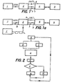
- a first line connects the manager to microprocessor and allows to send the pulses of fixed time base.
- the oscillator system consists of two oscillators, one, called the main oscillator, delivering the normal frequency, and the other one, says oscillator secondary, delivering the secondary frequency.
- the manager cuts power to oscillator main when the secondary oscillator, generating the secondary frequency of value lower than the frequency normal, is selected by the manager.
- the only signals remaining on the second line are those generated by the secondary oscillator.
- the normal frequency is 4 MHz and the secondary frequency of 250 KHz. In the case of a frequency divider, this secondary frequency is not other than the normal frequency divided by 16 by the manager.
- the transition to the active state can also be determined by the arrival of an interrupt which is itself the consequence of an external event: arrival of a tax impulse from the central, entry of a room into a slot, supply voltage monitoring, etc.
- the order communicated to the manager by the microprocessor depends on the activity of this microprocessor. he can decide to switch or stay on normal frequency if the need arises (e.g. timing a period such as the duration corresponding to a tax). When controls have determined the absence of timing, the microprocessor orders the manager to go to standby state.
- the manager varies the frequency. clock intermittently between values discreet. This achievement is different from a realization in which all the values of frequencies between a minimum and a maximum can a priori be chosen.
- the frequency can only take two values: the value of the normal frequency of the base of the microprocessor, called normal frequency, and a lower value, called secondary frequency, chosen to lower the power consumption of the microprocessor when conditions allow it to put in the inactive state.
- the oscillator system consists of a single oscillator, delivering the normal frequency, and the manager consists of a frequency divider.
- the circuits 5 controlled by the microprocessor 4 when it is in the active state, are connected to it by a bus address 15, known per se.
- Figure 2 shows a flowchart detailing the process where manager 2 goes to the normal frequency following an interrupt, then tries then switch back to the secondary frequency generating electrical energy savings.
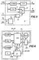
- FIG. 3 represents a block diagram of the clock manager 2 incorporating a frequency divider in the case of a single oscillator.
- This manager 2 is part of the specific integrated circuit of an application called ASIC.
- the oscillator 1 is connected to the manager 2 by the point CKIN, and delivers a fixed frequency of 4 MHz in the present example.
- the microprocessor 4 is connected to the manager 2 by the second line 6 which leads to the point CKOUT. Between these two points, the manager comprises, in this embodiment of the invention, a divider 11 of the frequency by a power N of 2, N possibly varying.
- the maximum value of N is determined by the minimum frequency at which the microprocessor 4. can operate normally.
- the selection between the two frequencies is made either by the third line 7 (carrying the command hereinafter called SPEED) or by recognizing an interrupt using a comparator 12 connected to the addresses AO to A15 of the address bus 15
- the reference 13 represents an OR function, consisting on the one hand of a type D flip-flop which stores the state of the comparator 12 (arrival of an interrupt) in synchronism with the execution of the internal orders of the microprocessor 4 , and on the other hand the specific control of the microprocessor 4 (line 7), these two conditions determining the position of the switch 14, and therefore the frequency conveyed by the line 6.
- the base frequency fixed time is 20 milliseconds.
- This base of fixed time is also part of the integrated circuit specific of an application called ASIC represented in the figure 3. It notably includes two dividers in cascade, one dividing by 4000, and the other by an integer P varying from 1 to 128.
- ASIC application specific of an application
- P varying from 1 to 128.
- N equal to 20.
- This value has the advantage of allowing the use of clock pulses to generate signals sent from the station's numeric keypad, when the station calls a telephone number formed by the user on the keyboard.
- Keyboard signals are made at a frequency can vary, in most countries, between a high value "HIGH”, corresponding to a period of 40 ms, and a low value "LOW", corresponding to a 60 ms period.
- a 16.6 ms time base is required to form a call number. This is the reason for the presence of a divider by P.
- the value of P is adjusted before delivery from the station. By the way, 20 ms is the maximum allowed to prevent the system from detection of parts introduced into the slot station payment does not lose coins entered immediately following each other.
- the telephone line delivers approximately 150 mW. More the frequencies used are low, or conversely high periods plus the smart part of the station is energy efficient and the more energy left can be stored in order, for example, to activate the magnets of the coin selector.
- Figure 4 shows schematically, on the logic plate of the station, the layout of the logic circuits 5 of Figure 1, with the connection of the different components by means of the address bus 15, represented by arrows wide, in the present exemplary embodiment. It goes from self lean arrows can also understand several conductors, or more generally several signal transmission means, for example by multiplexing.
- Address bus 15 connects the modem, meaning modulator-demodulator, the RTC, meaning Real Time Clock, the DTMF transceiver, meaning Dual Tone Multi Frequency, the CPU, meaning Central Processing Unit, memory M and I2C interface.
- the address bus 15, or taxiway includes addresses of most significant A8 to A15 and least significant addresses A0 to A7 from a demultiplexer (not shown). Every type of interrupt corresponds to an address, which allows in particular to manager 2, when an address corresponding to a switch appears on the bus address 15, to switch to normal frequency.
- a further reduction in frequency to 10 KHz or even less has a corresponding reduction of the electrical energy consumed by the microprocessor 4.
Landscapes
- Engineering & Computer Science (AREA)
- Computer Networks & Wireless Communication (AREA)
- Computer Security & Cryptography (AREA)
- Signal Processing (AREA)
- Power Sources (AREA)
- Prepayment Telephone Systems (AREA)
- Microcomputers (AREA)
- Elimination Of Static Electricity (AREA)
- Electrotherapy Devices (AREA)
- Preparation Of Compounds By Using Micro-Organisms (AREA)
- Manufacture, Treatment Of Glass Fibers (AREA)
- Telephone Set Structure (AREA)
- Control Of Steam Boilers And Waste-Gas Boilers (AREA)
- Management Or Editing Of Information On Record Carriers (AREA)
- Feedback Control In General (AREA)
- Communication Control (AREA)
- Input Circuits Of Receivers And Coupling Of Receivers And Audio Equipment (AREA)
Claims (9)
- Verfahren zur Verminderung des mittleren elektrischen Energieverbrauchs einer Fernsprechstelle mit einem Mikroprozessor (4) sowie ein Verwalter (2), um die an den Mikroprozessor (4) angelegte Taktfrequenz variieren zu können, wobei das Verfahren darin besteht, die an den Mikroprozessor (4) angelegte Frequenz vorübergehend zu verringern, dadurch gekennzeichnet, dass dieser Mikroprozessor (4) mehrere Male pro Sekunde zwischen Zuständen der Aktivität und Zuständen der Inaktivität kommutiert und bei der. Kommutierung in den Inaktivzustand über eine dritte Leitung (7) dem Verwalter (2) die Herabsetzung der Taktfrequenz befiehlt, und dass der Verwalter (2) das Eintreten des Mikroprozessors (4) in einen Zustand der Aktivität aufspürt und die Taktfrequenz des Mikroprozessors (4) auf ihren normalen Wert zurückführt und dem Mikroprozessor (4) über eine erste Leitung (3) einen Impuls der festen Zeitbasis liefert.
- Verfahren gemäß Anspruch 1, dadurch gekennzeichnet, dass die Kommutierung zwischen den Zuständen von Aktivität und den Zuständen von Inaktivität 50mal pro Sekunde erfolgt.
- Verfahren gemäß Anspruch 1, dadurch gekennzeichnet, dass das Aufspüren des Eintretens des Mikroprozessors (4) in einen Zustand der Aktivität durch das Erkennen eines Unterbrechungssignals erfolgt.
- Vorrichtung zur Verminderung des mittleren elektrischen Energieverbrauchs einer Fernsprechstelle mit einem Mikroprozessor (4), der in der Lage ist, vorübergehend von einem Zustand der Aktivität in einen energiesparenden Zustand der Inaktivität überzugehen, wobei ein System von Oszillatoren (1, 1') die Zeitimpulse liefert, die für den Betrieb des Mikroprozessors (4) erforderlich sind, sowie mit einem Verwalter (2), der dafür eingerichtet ist, die beim Mikroprozessor (4) anlangende Taktfrequenz variieren zu lassen, dadurch gekennzeichnet, dass der Verwalter (2) über Mittel verfügt, um den Übergang des Mikroprozessors (4) vom Zustand der Inaktivität in den aktiven Zustand zu erkennen, sowie Mittel, um an den benannten Mikroprozessor (4) die normale Frequenz anzulegen, wie auch Mittel, um dem Mikroprozessor (4) über eine erste Leitung (3) einen Impuls der festen Zeitbasis zu liefern, und dadurch, dass der Mikroprozessor (4) über eine dritte Leitung (7) verfügt, um dem Verwalter (2) den Übergang zur verringerten Frequenz zu befehlen, bevor er sich in den Zustand der Inaktivität begibt.
- Vorrichtung gemäß Anspruch 4, dadurch gekennzeichnet, dass die Mittel zum Erkennen des Übergangs des Mikroprozessors (4) vom Zustand der Inaktivität in den aktiven Zustand so eingerichtet sind, dass sie die Ankunft eines Unterbrechungssignals beim Mikroprozessor (4) interpretieren.
- Vorrichtung gemäß Ansprüchen 4 und 5, dadurch gekennzeichnet, dass der Verwalter (2) über Mittel verfügt, um die Taktfrequenz in diskontinuierlicher Weise variieren zu lassen.
- Vorrichtung gemäß Ansprüchen 4 bis 6, dadurch gekennzeichnet, dass der Verwalter (2) ein Oszillatorsystem umfaßt, das aus einem einzigen Oszillator besteht, und dadurch, dass der Verwalter (2) einen Frequenzteiler zur Erzeugung der verringerten Frequenz umfaßt.
- Vorrichtung gemäß Anspruch 7, dadurch gekennzeichnet, dass das Oszillatorsystem zwei Oszillatoren umfaßt, wobei der eine (1), Hauptoszillator genannt, die höhere Frequenz, normale Frequenz genannt, liefert, während der andere (1'), Nebenoszillator genannt, die geringere Frequenz, verminderte Frequenz genannt, liefert, und dass der Verwalter (2) Mittel umfaßt, um den Hauptoszillator (1) auszuschalten, wenn die Nebenfrequenz für den Zustand der Inaktivität genügt, und ihn wieder einzuschalten, wenn die normale Frequenz für die Arbeit des Mikroprozessors (4) erforderlich ist.
- Vorrichtung gemäß Anspruch 8, dadurch gekennzeichnet, dass die normale Frequenz 4 MHz, die verminderte Frequenz 250 kHz und die Frequenz der festen Zeitbasis 50 Hz beträgt.
Applications Claiming Priority (4)
| Application Number | Priority Date | Filing Date | Title |
|---|---|---|---|
| CH80592 | 1992-03-12 | ||
| CH805/92 | 1992-03-12 | ||
| CH80592 | 1992-03-12 | ||
| PCT/CH1993/000064 WO1993018608A1 (fr) | 1992-03-12 | 1993-03-10 | Procede et dispositif permettant la reduction de consommation de puissance dans un telephone publique |
Publications (2)
| Publication Number | Publication Date |
|---|---|
| EP0593690A1 EP0593690A1 (de) | 1994-04-27 |
| EP0593690B1 true EP0593690B1 (de) | 2003-10-01 |
Family
ID=4195604
Family Applications (1)
| Application Number | Title | Priority Date | Filing Date |
|---|---|---|---|
| EP93903792A Expired - Lifetime EP0593690B1 (de) | 1992-03-12 | 1993-03-10 | Verfahren und vorrichtung zur reduzierung des leistungsverbrauchs in einem öffentlichem fernsprechgerät |
Country Status (9)
| Country | Link |
|---|---|
| US (1) | US5499201A (de) |
| EP (1) | EP0593690B1 (de) |
| KR (1) | KR100304138B1 (de) |
| AT (1) | ATE251368T1 (de) |
| DE (1) | DE69333222T2 (de) |
| ES (1) | ES2206454T3 (de) |
| FI (1) | FI934977A (de) |
| NO (1) | NO308977B1 (de) |
| WO (1) | WO1993018608A1 (de) |
Families Citing this family (4)
| Publication number | Priority date | Publication date | Assignee | Title |
|---|---|---|---|---|
| US8312310B2 (en) * | 2007-05-01 | 2012-11-13 | Canon Kabushiki Kaisha | Apparatus and method for changing clock frequency and modulation method based on current state |
| US9854659B2 (en) * | 2014-10-16 | 2017-12-26 | Advanced Energy Industries, Inc. | Noise based frequency tuning and identification of plasma characteristics |
| CN110870039B (zh) | 2017-07-07 | 2022-09-16 | 先进能源工业公司 | 等离子体功率输送系统的周期间控制系统及其操作方法 |
| US11804362B2 (en) | 2018-12-21 | 2023-10-31 | Advanced Energy Industries, Inc. | Frequency tuning for modulated plasma systems |
Family Cites Families (17)
| Publication number | Priority date | Publication date | Assignee | Title |
|---|---|---|---|---|
| US4097923A (en) * | 1975-04-16 | 1978-06-27 | Pitney-Bowes, Inc. | Remote postage meter charging system using an advanced microcomputerized postage meter |
| US5274843A (en) * | 1987-11-28 | 1993-12-28 | Kabushiki Kaisha Toshiba | Paging apparatus having a battery saving function |
| US5204986A (en) * | 1988-02-25 | 1993-04-20 | Kabushiki Kaisha Toahiba | Battery powered radio devices having a battery saving function |
| JPH0642691B2 (ja) * | 1988-05-21 | 1994-06-01 | 富士通株式会社 | 移動電話端末 |
| US4979208A (en) * | 1988-06-29 | 1990-12-18 | Mars Incorporated | Method and apparatus for electronic payphone open switch interval management |
| US5041964A (en) * | 1989-06-12 | 1991-08-20 | Grid Systems Corporation | Low-power, standby mode computer |
| US5142684A (en) * | 1989-06-23 | 1992-08-25 | Hand Held Products, Inc. | Power conservation in microprocessor controlled devices |
| US5021679A (en) * | 1989-06-30 | 1991-06-04 | Poqet Computer Corporation | Power supply and oscillator for a computer system providing automatic selection of supply voltage and frequency |
| US5222239A (en) * | 1989-07-28 | 1993-06-22 | Prof. Michael H. Davis | Process and apparatus for reducing power usage microprocessor devices operating from stored energy sources |
| US4964121A (en) * | 1989-08-30 | 1990-10-16 | Motorola, Inc. | Battery saver for a TDM system |
| JPH0491534A (ja) * | 1990-08-06 | 1992-03-25 | Furukawa Electric Co Ltd:The | 消費電流制御装置 |
| JPH0496810A (ja) * | 1990-08-13 | 1992-03-30 | Matsushita Electric Ind Co Ltd | 情報端末装置 |
| US5148380A (en) * | 1990-08-27 | 1992-09-15 | Acer Incorporated | Method and apparatus for conserving power in a data processing system |
| JPH0511876A (ja) * | 1990-12-25 | 1993-01-22 | Mitsubishi Electric Corp | デイジタル回路装置 |
| FI88657C (fi) * | 1991-02-12 | 1993-06-10 | Nokia Mobile Phones Ltd | Foerfarande foer att minska stroemfoerbrukningen i en mobiltelefon |
| JPH0776894B2 (ja) * | 1991-02-25 | 1995-08-16 | インターナショナル・ビジネス・マシーンズ・コーポレイション | プロセッサ用クロック信号の制御方法及び情報処理システム |
| US5369771A (en) * | 1991-12-23 | 1994-11-29 | Dell U.S.A., L.P. | Computer with transparent power-saving manipulation of CPU clock |
-
1993
- 1993-03-10 US US08/146,009 patent/US5499201A/en not_active Expired - Fee Related
- 1993-03-10 ES ES93903792T patent/ES2206454T3/es not_active Expired - Lifetime
- 1993-03-10 WO PCT/CH1993/000064 patent/WO1993018608A1/fr active IP Right Grant
- 1993-03-10 AT AT93903792T patent/ATE251368T1/de not_active IP Right Cessation
- 1993-03-10 KR KR1019930703425A patent/KR100304138B1/ko not_active IP Right Cessation
- 1993-03-10 DE DE69333222T patent/DE69333222T2/de not_active Expired - Fee Related
- 1993-03-10 EP EP93903792A patent/EP0593690B1/de not_active Expired - Lifetime
- 1993-11-09 NO NO934063A patent/NO308977B1/no not_active IP Right Cessation
- 1993-11-11 FI FI934977A patent/FI934977A/fi unknown
Also Published As
| Publication number | Publication date |
|---|---|
| ATE251368T1 (de) | 2003-10-15 |
| ES2206454T3 (es) | 2004-05-16 |
| US5499201A (en) | 1996-03-12 |
| FI934977A0 (fi) | 1993-11-11 |
| NO934063L (no) | 1993-11-09 |
| DE69333222T2 (de) | 2004-08-26 |
| DE69333222D1 (de) | 2003-11-06 |
| KR100304138B1 (ko) | 2001-11-22 |
| EP0593690A1 (de) | 1994-04-27 |
| FI934977A (fi) | 1993-11-11 |
| NO308977B1 (no) | 2000-11-20 |
| WO1993018608A1 (fr) | 1993-09-16 |
| NO934063D0 (no) | 1993-11-09 |
Similar Documents
| Publication | Publication Date | Title |
|---|---|---|
| KR100296993B1 (ko) | 패킷스위치의용장화스위칭플레인을처리하는방법및이방법을수행하는패킷스위치 | |
| FR2711463A1 (fr) | Procédé de commande adaptative de récepteur radio et dispositif associé. | |
| EP0703717B1 (de) | Batteriesparanordnung eines Systemes mit einem an ein Peripheriegerät angeschlossenen Funktelefon | |
| EP0593690B1 (de) | Verfahren und vorrichtung zur reduzierung des leistungsverbrauchs in einem öffentlichem fernsprechgerät | |
| FR2803974A1 (fr) | Procedes de souscription entre une station mobile et une station de base dans un reseau de telecommunications, et systemes les mettant en oeuvre | |
| FR2844086A1 (fr) | Procede de commande a faible consommation de courant d'un dispositif de reception et dispositif de reception associe | |
| JP2940969B2 (ja) | 電話ライン給電電話機 | |
| FR2796238A1 (fr) | Borne publique d'acces a un reseau informatique | |
| EP0815527B1 (de) | Koppler zur kommunikationsverwaltung zwischen einem tragbaren träger und einer datenaustauschvorrichtung und datenaustauschvorrichtung dafür | |
| EP0954770B1 (de) | Uhr mit detektions- und sparvorrichtungen im falle von nicht ausreichender energieversorgung | |
| FR2571870A1 (fr) | Dispositif de sauvegarde de memoire de microprocesseur. | |
| CN105282298A (zh) | 一种手机熄屏方法及装置 | |
| EP1107120A1 (de) | Vorrichtung mit Energieversorgungseinrichtung und Verfahren zum Anlaufen/Wiederanlaufen der unter Mikrostromversorgungsausfällen unterworfenen Vorrichtungen | |
| EP0571847B1 (de) | Rufempfänger mit geringem Energieverbrauch | |
| FR2540646A1 (fr) | Horloge electronique fonctionnant sur le secteur, notamment horloge a contacts a reserve de marche | |
| FR2646305A1 (fr) | Dispositif electronique de codage, notamment pour publiphone | |
| CN114338908B (zh) | 一种sim卡恢复方法、装置、芯片及模组设备 | |
| EP0853265B1 (de) | Mit photovoltaischer Zelle funktionierendes elektronisches Gerät, insbesondere Zeitmesswerk | |
| JP2828132B2 (ja) | 移動電話端末及び移動電話端末の制御方法 | |
| FR2774784A1 (fr) | Microprocesseur comportant un systeme de synchronisation avec un evenement asynchrone attendu | |
| FR2750282A1 (fr) | Telephone mobile | |
| CA2332692A1 (en) | Telephone line powered central office drop and reconnect method and apparatus | |
| JPH0258936A (ja) | 選択呼出受信機 | |
| EP1175016B1 (de) | Integrierte Schaltung mit aktiven und inaktiven Betriebsmodus und Vorrichtung die diese Schaltung enthält | |
| EP4361768A1 (de) | Leistungsverwaltung in einem nfc-nahfeldkommunikationssteuergerät |
Legal Events
| Date | Code | Title | Description |
|---|---|---|---|
| PUAI | Public reference made under article 153(3) epc to a published international application that has entered the european phase |
Free format text: ORIGINAL CODE: 0009012 |
|
| 17P | Request for examination filed |
Effective date: 19931201 |
|
| AK | Designated contracting states |
Kind code of ref document: A1 Designated state(s): AT CH DE DK ES FR GB GR LI NL PT SE |
|
| 17Q | First examination report despatched |
Effective date: 19961004 |
|
| RAP1 | Party data changed (applicant data changed or rights of an application transferred) |
Owner name: ELECTROWATT TECHNOLOGY INNOVATION AG |
|
| RAP1 | Party data changed (applicant data changed or rights of an application transferred) |
Owner name: IP-TPG HOLDCO S.A.R.L. |
|
| GRAG | Despatch of communication of intention to grant |
Free format text: ORIGINAL CODE: EPIDOS AGRA |
|
| GRAG | Despatch of communication of intention to grant |
Free format text: ORIGINAL CODE: EPIDOS AGRA |
|
| GRAH | Despatch of communication of intention to grant a patent |
Free format text: ORIGINAL CODE: EPIDOS IGRA |
|
| 19U | Interruption of proceedings before grant |
Effective date: 20010206 |
|
| 19W | Proceedings resumed before grant after interruption of proceedings |
Effective date: 20020904 |
|
| GRAH | Despatch of communication of intention to grant a patent |
Free format text: ORIGINAL CODE: EPIDOS IGRA |
|
| RAP1 | Party data changed (applicant data changed or rights of an application transferred) |
Owner name: IPM INTERNATIONAL SA |
|
| GRAA | (expected) grant |
Free format text: ORIGINAL CODE: 0009210 |
|
| AK | Designated contracting states |
Kind code of ref document: B1 Designated state(s): AT CH DE DK ES FR GB GR LI NL PT SE |
|
| PG25 | Lapsed in a contracting state [announced via postgrant information from national office to epo] |
Ref country code: AT Free format text: LAPSE BECAUSE OF FAILURE TO SUBMIT A TRANSLATION OF THE DESCRIPTION OR TO PAY THE FEE WITHIN THE PRESCRIBED TIME-LIMIT Effective date: 20031001 |
|
| REG | Reference to a national code |
Ref country code: GB Ref legal event code: FG4D Free format text: NOT ENGLISH |
|
| REG | Reference to a national code |
Ref country code: CH Ref legal event code: EP |
|
| REF | Corresponds to: |
Ref document number: 69333222 Country of ref document: DE Date of ref document: 20031106 Kind code of ref document: P |
|
| REG | Reference to a national code |
Ref country code: CH Ref legal event code: NV Representative=s name: LEMAN CONSULTING S.A. |
|
| PG25 | Lapsed in a contracting state [announced via postgrant information from national office to epo] |
Ref country code: SE Free format text: LAPSE BECAUSE OF FAILURE TO SUBMIT A TRANSLATION OF THE DESCRIPTION OR TO PAY THE FEE WITHIN THE PRESCRIBED TIME-LIMIT Effective date: 20040101 Ref country code: GR Free format text: LAPSE BECAUSE OF FAILURE TO SUBMIT A TRANSLATION OF THE DESCRIPTION OR TO PAY THE FEE WITHIN THE PRESCRIBED TIME-LIMIT Effective date: 20040101 Ref country code: DK Free format text: LAPSE BECAUSE OF FAILURE TO SUBMIT A TRANSLATION OF THE DESCRIPTION OR TO PAY THE FEE WITHIN THE PRESCRIBED TIME-LIMIT Effective date: 20040101 |
|
| GBT | Gb: translation of ep patent filed (gb section 77(6)(a)/1977) |
Effective date: 20040123 |
|
| REG | Reference to a national code |
Ref country code: ES Ref legal event code: FG2A Ref document number: 2206454 Country of ref document: ES Kind code of ref document: T3 |
|
| PLBE | No opposition filed within time limit |
Free format text: ORIGINAL CODE: 0009261 |
|
| STAA | Information on the status of an ep patent application or granted ep patent |
Free format text: STATUS: NO OPPOSITION FILED WITHIN TIME LIMIT |
|
| 26N | No opposition filed |
Effective date: 20040702 |
|
| REG | Reference to a national code |
Ref country code: CH Ref legal event code: PCAR Free format text: LEMAN CONSULTING S.A.;CHEMIN DE PRECOSSY 31;1260 NYON (CH) |
|
| PG25 | Lapsed in a contracting state [announced via postgrant information from national office to epo] |
Ref country code: PT Free format text: LAPSE BECAUSE OF NON-PAYMENT OF DUE FEES Effective date: 20040301 |
|
| PGFP | Annual fee paid to national office [announced via postgrant information from national office to epo] |
Ref country code: ES Payment date: 20090324 Year of fee payment: 17 |
|
| PGFP | Annual fee paid to national office [announced via postgrant information from national office to epo] |
Ref country code: NL Payment date: 20090317 Year of fee payment: 17 |
|
| PGFP | Annual fee paid to national office [announced via postgrant information from national office to epo] |
Ref country code: GB Payment date: 20090325 Year of fee payment: 17 Ref country code: CH Payment date: 20090316 Year of fee payment: 17 |
|
| PGFP | Annual fee paid to national office [announced via postgrant information from national office to epo] |
Ref country code: DE Payment date: 20090320 Year of fee payment: 17 |
|
| PGFP | Annual fee paid to national office [announced via postgrant information from national office to epo] |
Ref country code: FR Payment date: 20090312 Year of fee payment: 17 |
|
| REG | Reference to a national code |
Ref country code: NL Ref legal event code: V1 Effective date: 20101001 |
|
| REG | Reference to a national code |
Ref country code: CH Ref legal event code: PL |
|
| GBPC | Gb: european patent ceased through non-payment of renewal fee |
Effective date: 20100310 |
|
| REG | Reference to a national code |
Ref country code: FR Ref legal event code: ST Effective date: 20101130 |
|
| PG25 | Lapsed in a contracting state [announced via postgrant information from national office to epo] |
Ref country code: NL Free format text: LAPSE BECAUSE OF NON-PAYMENT OF DUE FEES Effective date: 20101001 Ref country code: FR Free format text: LAPSE BECAUSE OF NON-PAYMENT OF DUE FEES Effective date: 20100331 |
|
| PG25 | Lapsed in a contracting state [announced via postgrant information from national office to epo] |
Ref country code: LI Free format text: LAPSE BECAUSE OF NON-PAYMENT OF DUE FEES Effective date: 20100331 Ref country code: DE Free format text: LAPSE BECAUSE OF NON-PAYMENT OF DUE FEES Effective date: 20101001 Ref country code: CH Free format text: LAPSE BECAUSE OF NON-PAYMENT OF DUE FEES Effective date: 20100331 |
|
| PG25 | Lapsed in a contracting state [announced via postgrant information from national office to epo] |
Ref country code: GB Free format text: LAPSE BECAUSE OF NON-PAYMENT OF DUE FEES Effective date: 20100310 |
|
| REG | Reference to a national code |
Ref country code: ES Ref legal event code: FD2A Effective date: 20110418 |
|
| PG25 | Lapsed in a contracting state [announced via postgrant information from national office to epo] |
Ref country code: ES Free format text: LAPSE BECAUSE OF NON-PAYMENT OF DUE FEES Effective date: 20110404 |
|
| PG25 | Lapsed in a contracting state [announced via postgrant information from national office to epo] |
Ref country code: ES Free format text: LAPSE BECAUSE OF NON-PAYMENT OF DUE FEES Effective date: 20100311 |