EP0593293A2 - Serieller Stossdrucker - Google Patents
Serieller Stossdrucker Download PDFInfo
- Publication number
- EP0593293A2 EP0593293A2 EP93308194A EP93308194A EP0593293A2 EP 0593293 A2 EP0593293 A2 EP 0593293A2 EP 93308194 A EP93308194 A EP 93308194A EP 93308194 A EP93308194 A EP 93308194A EP 0593293 A2 EP0593293 A2 EP 0593293A2
- Authority
- EP
- European Patent Office
- Prior art keywords
- spacer
- platen
- projections
- impact printer
- Prior art date
- Legal status (The legal status is an assumption and is not a legal conclusion. Google has not performed a legal analysis and makes no representation as to the accuracy of the status listed.)
- Withdrawn
Links
Images


Classifications
-
- B—PERFORMING OPERATIONS; TRANSPORTING
- B41—PRINTING; LINING MACHINES; TYPEWRITERS; STAMPS
- B41J—TYPEWRITERS; SELECTIVE PRINTING MECHANISMS, i.e. MECHANISMS PRINTING OTHERWISE THAN FROM A FORME; CORRECTION OF TYPOGRAPHICAL ERRORS
- B41J11/00—Devices or arrangements of selective printing mechanisms, e.g. ink-jet printers or thermal printers, for supporting or handling copy material in sheet or web form
- B41J11/02—Platens
- B41J11/10—Anvil or like character-size platens
-
- B—PERFORMING OPERATIONS; TRANSPORTING
- B41—PRINTING; LINING MACHINES; TYPEWRITERS; STAMPS
- B41J—TYPEWRITERS; SELECTIVE PRINTING MECHANISMS, i.e. MECHANISMS PRINTING OTHERWISE THAN FROM A FORME; CORRECTION OF TYPOGRAPHICAL ERRORS
- B41J11/00—Devices or arrangements of selective printing mechanisms, e.g. ink-jet printers or thermal printers, for supporting or handling copy material in sheet or web form
- B41J11/20—Platen adjustments for varying the strength of impression, for a varying number of papers, for wear or for alignment, or for print gap adjustment
Definitions
- the present invention relates to a serial impact printer which conducts printing of characters and the like on a print medium by impacting thereon through print wires and more particularly to a serial impact printer having projections on a platen, each of the projections being opposed to each of print wires, so that the characters and the like can be clearly printed on print medium in which plural copyable sheets such as carbon copy papers are bound into one form.
- Impact printers are utilized in simultaneous printing of characters and the like on copyable print sheets in which pressure sensitive sheets such as carbon copy papers are bound into one form.
- pressure sensitive sheets such as carbon copy papers are bound into one form.
- the characters and the like can be clearly printed on all of the copyable print sheets in case that print form in which plural copyable print sheets (for example, 10 sheets ) are bound into one form is utilized.
- projections 94a, 94c each having the same height as the projection 94b, are formed near both sides of the projection 94b and the projections 94a, 94c are contacted with the print medium P same as the projection 94b.
- pressures P3, P4 yielded by the projections 94a, 94c are exerted to the print medium P.
- unnecessary shades occur on the lower sheet in the print medium P which is made pressure sensitive because the print medium P is comprised copyable sheets such as carbon copy papers.
- a serial impact printer having a movable print head with a plurality of print wires and a platen arranged oppositely to the print head, the platen supporting a print medium thereon and moving synchronously with the print head, the serial impact printer comprising: a plurality of projections formed on a projecting member which is mounted on the platen, each of the projections having a top surface and being opposed to each of the print wires, a spacer with an upper surface arranged near the projections, the spacer being more deformable than the projections against impact power yielded by the print wires, and wherein printing is conducted on the print medium while the print medium is retained between the projection and the print wire impacted toward the projection.
- the print wires in the print head are impacted to the print medium. And such printing is done while the print medium is retained between the projection and the print wire.
- impact power yielded by the print wire is concentrated in a small area, where the print wire and the projection are opposed with each other, without being dispersed and thereby the characters and the like can be clearly printed on the area impacted by the print wire.
- the spacer arranged near the projections supports the print medium when impacted by the print wire and thus the spacer prevents another projections from exerting strong pressure to the print medium.
- the spacer since the spacer is more deformable than the projections and supports the print medium on a wider area than the projections, the spacer exerts only a very weak Pressure to the print medium.
- the spacer disperses the impact power from the print wires and the pressure yielded from the projection opposed to the print wires which are not impacted is very weak. Therefore, it can hinder unnecessary shades from being formed on the copyable sheets existing lower position in the print medium. As a result, in particular, the characters and the like can be clearly printed with high printing quality on the print medium in which a plurality of copyable sheets are bound into one form.
- a print head 2 is mounted on a head carriage 5 movably supported through both a main guide bar 3 and a sub guide bar 4, the guide bars 3, 4 being fixed to side frames (not shown ) of the printer 1.
- the print head 2 can be reciprocally moved along axial directions of the guide bars 3, 4 while being retained at a position opposing a print position on a print medium P inserted between the print head 2 and a platen 6.
- a plurality of copyable sheets are bound into one form.
- the platen 6 is supported to a plate spring 7 which is mounted in a frame 8 and the frame 8 is mounted on a platen carriage 11 which is movably supported through both a main guide bar 9 and a sub guide bar 10.
- the platen 6 can be reciprocally moved along axial directions of the guide bars 9, 10 while being opposed to the print medium P existing between the platen 6 and the print head 2.
- the guide bars 3, 4 and the guide bars 9, 10 are arranged so that each of the guide bars 3, 4, 9 and 10 is made parallel with each other.
- the head carriage 5 mounting the print head 2 thereon and the platen carriage 11 mounting the platen 6 thereon are fixed to a timing belt 12, 13 respectively so that both the head carriage 5 and the platen carriage 11 are moved synchronously with each other.
- the timing belt 12 is equipped between a pair of rollers 15 ( one of the rollers 15 is shown in Fig. 1 ) which are fixed to driving shafts 14 ( one of the shafts 14 is shown in Fig. 1 ) extended to a direction normal to the axial direction of the guide bar 3.
- the timing belt 13 is equipped between a pair of rollers 16 ( one of the rollers 16 is shown in Fig.
- the roller 16 has the same diameter of the roller 15 ) which are fixed to the driving shaft 14 extended to a direction normal to the axial direction of the guide bar 9.
- the driving shaft 14 is connected to a wellknown driving mechanism driven by a driving motor (not shown ) so that the head carriage 5 and the platen carriage 11 are synchronously moved through the rollers 15, 16 and the timing belts 12, 13.
- a pair of sheet feed rollers 17a, 17b are positioned at an upstream position of sheet feed direction and a pair of sheet feed rollers 18a, 18b are positioned at a downstream position of the sheet feed direction so that the print medium P is fed from lower position to upper position in Fig. 2.
- a flexible printed circuit film 19 is connected and thereby print data is transmitted to the print head 2 from a control device (not shown ) so that the print head 2 prints the characters and the like onto the print medium P according to the print data transmitted from the control device.
- each of the print units has a print wire to impact the print medium P, a piezoelectric member to drive the print wire and a force transmitting mechanism to transmit displacement of the piezoelectric member to the print wire after enlarging the displacement. Since such construction of the print unit is wellknown, explanation thereof is omitted.
- a piezoelectric member 20 is arranged on the lower surface of the plate spring 7 (the lower surface is opposite side of the upper surface on which the platen 6 is mounted ).
- the thus piezoelectric member 20 is constructed to conduct vibrating motion toward the platen 6 in response to alternating current in a frequency range of several kHz - ultrasonic.
- a wellknown control circuit in which thickness and quality of the print medium P is detected by a sensor and it is judged based on signal from the sensor whether vibration is to be given to the platen 6 through the piezoelectric member 20, is arranged.
- the control circuit judges that the vibration is to be given to the platen 6 if a print format in which a plurality of copyable sheets such as the carbon copy papers are bound into one form is used as the print medium P, and the alternating current is input to the piezoelectric member 20.
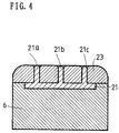
- a projecting member 21 is embedded on a surface of the platen 6 opposite to the print head 2.
- the projecting member 21 has a plurality of projections 21a, 21b, 21c, each of which has the same diameter as that of top portion of the print wire.
- three projections 21a, 21b and 21c are shown in Fig.4 to easily understand.
- each of the projections 21a, 21b and 21c is opposed to each of the print wires in the print head 2 with a relation of 1:1.
- the materials forming the projecting member 21 it is desirable the materials having enough hardness and durability such as sintered hard alloy, tungsten, ceramic zirconia and the projecting member 21 is made of the above material separately from the platen 6. And the projecting member 21 is fixed onto the surface of the platen 6 made of stainless steel to embed in a recess formed on the surface of the platen 6 and to adhere therein.
- a spacer 23 is fixed onto the surface of the platen 6 so that the spacer 23 surrounds each of the projections 21a, 21b and 21c and the upper surface of the spacer 23 has a height substantially same as the height of the projections 21a, 21b and 21c.
- materials forming the spacer 23 it is desirable the materials, which act as cushion, made of synthesized polymer having softness and deformability. For instance, it is desirable urethane, silicon rubber, foamed rubber, as the spacer 23.
- the thus spacer 23 is adhered onto the surface of the platen 6 through adhesive.
- the print medium P is fed to a predetermined print position through the sheet feed rollers 17a, 17b and the sheet feed rollers 18a, 18b from the lower position to the upper position along the sheet feed direction.
- the print wires in the print head 2 controlled based on the print data transmitted from the control device impact the print medium P fed to the print position through a ink ribbon IR. Thereby, the characters and the like are printed on the print medium P.
- the print medium P is the print form in which the plural carbon copy papers are bound into one form
- the uppermost sheet (the first sheet ) is printed through the ink ribbon IR and on the other hand, the second sheet and the other sheets under the second sheet are copied by impact power of the print wires.
- alternating current is input to the piezoelectric member 20.
- the piezoelectric member 20 is vibrated toward the platen 6 and the platen 6 is vibrated through the plate spring 7.
- the frequency of the vibration is suitably set so that the vibration of one time to several times is given to the platen 6 while the print wires are contacted to the print medium P.
- the drive shaft 14 is rotated by the drive motor (not shown ) in synchronism with signal transmission of the print data from a host computer (not shown ) and thus the rollers 15, 16 are rotated according to the rotation of the drive shaft 14.
- the head carriage 5 mounting the print head 2 thereon is moved along the print surface of the print medium P by the timing belt 12 and at the same time, following to movement of the head carriage 5, the platen carriage 11 mounting the platen 6 thereon is moved along the hinder surface of the print medium P by the timing belt 13.
- moving speed of both the head carriage 5 and the platen carriage 11 is exactly same because the roller 15 has the same diameter as that of the roller 16.
- the platen 6 is moved along the hinder surface of the print medium P while the vibration is given thereto by the piezoelectric member 20, in synchronism with that the print head 2 is moved along the print surface of the print medium P. And after one line printing is conducted, the print medium P is fed toward upper direction by a predetermined amount through the sheet feed rollers 17a, 17b, 18a and 18b.
- the spacer 23 is deformed as shown in Fig. 5 and is recessed around the projection 21b opposed to the print wire 25b.
- the projection 21b since the projection 21b is not easily deformed, the pressure P2 is exerted to the print medium P from the projection 21b. Therefore, pressure for printing is concentrated on a small area between the print wire 25b and the projection 21b and thus the characters and the like are clearly printed on the print medium P. Further, since pressure occurring in printing is dispersed and absorbed based on that the spacer 23 is softly deformed, the characters and the like are not printed on the second sheet and the other sheets under the uppermost sheet in the print medium P due to the pressure from the spacer 23.
- the projections 21a, 21c having the same height as that of the projection 21b, are positioned near both sides of the projection 21b, these projections 21a, 21c are surrounded by the spacer 23. Therefore, the projections 21a, 21c does not so strongly press the print medium P. As a result, unnecessary shades are not formed on the second sheet and the other sheets under the uppermost sheet in the print medium P.
- the impact power by the print wires is exerted to the print surface of the print medium P when printing is conducted and the pressure opposing to the impact pressure from the print wires is exerted to the hinder surface of the print medium P from the platen 6 by the projections.
- the vibrating power of the platen 6 may be exerted to the hinder surface of the print medium P if necessary. Therefore, the characters and the like can be clearly printed onto all of the copyable sheets in the print medium P in case that the print form in which a plurality of copyable sheets are bound into one form is used.
- the spacer 23 acts as the cushion which softly disperses the impact power of the print wires and thus the pressure yielded by the projections opposed to the print wires not used for printing is not so strong. Therefore, it can prevent unnecessary shades from being formed on the second copyable sheet and the other copyable sheets under the uppermost sheet.
- the serial impact printer according to the second embodiment essentially has the same construction as the serial impact printer 1 of the first embodiment except for construction of the platen 6. Therefore, only the construction of the platen 6 different from that of the first embodiment will be described in the following.
- a soft spacer 31 made of the synthesized polymer is arranged on the surface of the platen 6 so that the spacer 31 surrounds each of the projections 21a, 21b and 21c. And top portion in each of the projections 21a, 21b and 21c is slightly projected from the surface of the spacer 31.
- projecting length of each top portion is set about 0.3 mm.
- the above constructed platen 6 acts as follows. As shown in Fig. 7, in case that the print wire 25b impacts the print medium P ( in which the plural carbon copy papers are bound into one form ), the pressure P1 is exerted to the print medium P and thereby the print medium P is strongly moved to a direction A so that the print wire 25b becomes a pressing point.
- the top portion of the print wire 21b is slightly projected from the surface of the spacer 31. Therefore, at the time that impact printing is conducted, the impact power exerted from the print wire 25b is not absorbed by the spacer 31 and thus the projection 21b is sunk into the print medium P in comparison with the first embodiment ( see Fig. 5 ). As a result, the characters and the like can be more clearly printed on the print medium than the first embodiment.
- the print medium P is contacted with the surface of the spacer 31 around the projection 21b and movement of the print medium P toward the direction A is mitigated. Therefore, the print medium P is not impacted to the other projections 21a and 21c. As a result, it can prevent unnecessary shades from being printed on the second copyable sheet and the other copyable sheets under the uppermost sheet in the print medium P by the projections 21a and 21c. And since the spacer 31 is softly deformed to disperse the pressure yielded by the print wire 25b and the projection 21b, the copyable sheets are not colored by the pressure from the spacer 31.
- the length of the top portion in each of the projections 21a, 21b and 21c is desirably set in a range of 0.1 mm - 0.3 mm because the spacer 31 cannot satisfactorily act as the cushion if the length of the top portion is unnecessarily long. And such length is suitably selected in taking the impact power of the print wires and the distance between the projections into consideration.
- the serial impact printer of the second embodiment it can prevent unnecessary shades from being formed on the second copyable sheet and the other copyable sheets under the uppermost sheet. Additionally, at the time that the print medium P is impacted by the print wires, the print medium P does not contact to the surface of the spacer 31 and thus the impact power is not mitigated at that time. Therefore, the characters and the like can be more clearly printed on all of the copyable sheets in the print medium P than the first embodiment.
- a soft spacer 33 made of the synthesized polymer is arranged on the surface of the platen 6 so that the spacer 33 surrounds each of the projections 21a, 21b and 21c.
- top portion in each of the projections 21a, 21b and 21c is slightly projected from the surface of the spacer 33.
- projecting length of each top portion is set about 0.3 mm.
- a plurality of projected portions 35a, 35b, 35c and 35d are formed into one body. Each of the projected portions 35a, 35b, 35c and 35d is positioned between the projections 21a, 21b and 21c.
- the above constructed platen 6 acts as follows. As shown in Fig. 9, in case that the print wire 25b impacts the print medium P ( in which the plural carbon copy papers are bound into one form ), the pressure P1 is exerted to the print medium P and thereby the print medium P is strongly moved to a direction A so that the print wire 25b becomes a pressing point. And also in the third embodiment, since the top portion in each of the projections 21a, 21b and 21c is slightly projected from the surface of the spacer 33, the characters and the like can be clearly printed on all of the copyable sheets in the print medium P as in the second embodiment.
- the print medium P is supported by the projected portions 35b and 35c formed on the spacer 33 at areas separated from the projection 21b and thus the movement of the print medium P toward the direction A is mitigated. As a result, it can prevent unnecessary shades from being formed on the second copyable sheet and the other copyable sheets under the uppermost sheet in the print medium P.
- the spacer 33 is softly deformed to disperse the pressure yielded by the print wire 25b and the projection 21b, the copyable sheets are not colored by the pressure from the projected portions 35a and 35c of the spacer 31.
- a soft spacer 37 made of the synthesized polymer is arranged on the surface of the platen 6 so that the spacer 37 surrounds each of the projections 21a, 21b and 21c. And similar to the first embodiment, the surface of the spacer 37 is substantially coincided with the top surfaces of the projections 21a, 21b and 21c. Further, in the spacer 37, taper portions 39 are formed near the projections 21a, 21b and 21c.
- the above constructed platen 6 acts as follows. As shown in Fig. 11, in case that the print wire 25b impacts the print medium P ( in which the plural carbon copy papers are bound into one form ), the pressure P1 is exerted to the print medium P and thereby the print medium P is strongly moved to a direction A so that the print wire 25b becomes a pressing point. And also in the fourth embodiment, since the taper portions are formed near the projection 21b, at the time that impact printing is conducted, the impact power exerted from the print wire 25b is not absorbed by the spacer 37 and thus the projection 21b is sunk into the print medium P in comparison with the first embodiment ( see Fig. 5 ). As a result, the characters and the like can be more clearly printed on the print medium P than the first embodiment.
- the print medium P is supported by the spacer 37 at an area separated from the projection 21b and thus the movement of the print medium P toward the direction A is mitigated. As a result, it can prevent unnecessary shades from being formed on the second copyable sheet and the other copyable sheets under the uppermost sheet in the print medium P.
- the spacer 37 is softly deformed to disperse the pressure yielded by the print wire 25b and the projection 21b, the copyable sheets are not colored by the pressure from the spacer 37.
- the projections 21a, 21b and 21c of the projecting member 21 are arranged on the platen 6 with the same space therebetween.
- the print wires are not arranged with the same space therebetween in the print head of the serial impact printer. In that case, therefore, it is necessary to ununiformly arrange the projections according to the print wires in order to arrange the projections against the print wires with a relationship of 1:1. In such case, it is desirable to construct the platen 6 according to the fifth embodiment.
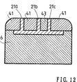
- each of the projections 21a, 21b and 21c is ununiformly arranged on the projecting member 21 so that the space between the projections 21a, 21b and the space between the projection 21b, 21c are different with each other.
- a spacer 41 is arranged at the left side of the projection 21b on the surface of the platen 6 and the another spacer 43 is arranged at the right side of th projection 21b on the surface of the platen 6.
- the spacers 41 and 43 are made of the soft synthesized polymer and the spacer 43 has more hardness and less deformability than the spacer 41.
- the above constructed platen 6 acts as follows. As shown in Fig. 13, in case that the print wire 25b impacts the print medium P ( in which the plural carbon copy papers are bound into one form ), the pressure P1 is exerted to the print medium P and thereby the print medium P is strongly moved to a direction A so that the print wire 25b becomes a pressing point. At this time, the print medium P is strongly pressed to the projection 21b and thereby the pressure P2 is exerted to the print medium P from the projection 21b. As a result, the pressure for printing is concentrated on a small area between the print wire 25b and the projection 21b and the characters and the like can be clearly printed on the print medium P.
- the spacer 43 with less deformability is arranged on a narrow area which is sectioned by the projections 21b and 21c.
- the projection 21c is not easily pressed to the print medium P based on that the spacer 43 is not easily deformed and therefore it can prevent unnecessary shades from being formed in spite of the spaces between the projections.
- the serial impact printer of the fifth embodiment utilizing the above constructed platen 6 it can prevent unnecessary shades from being formed on the second copyable sheet and the other copyable sheet under the uppermost sheet in the print medium P.
- the spacer 43 with less deformability is arranged on the narrow area sectioned by the projections 21b and 21c, it can prevent unnecessary shades from being formed on the copyable sheets in the print medium P.
- a thin metallic plate spring 51 which covers the projecting member 21 except for the projections, may be arranged in the platen 6 as the spacer. Taking into consideration that the spacer is continuously contacted to and frictioned with the print medium P, abrasion resistance of the spacer is eminently improved by utilizing the metallic plate spring 51 in comparison with the case that the spacer is made of the synthesized polymer.
- the plate spring 51 is used together with a cushion member 53 made of the synthesized polymer, the cushion member 53 being arranged under the plate spring 51 between the projections. And the plate spring 51 covers the projecting member 21 except for the projections and peripheral portion of the plate spring 51 is engaged in a recess formed in the platen 6.
- the plate spring 51 is reinforced by the cushion member 53 against the impact pressure exerted thereon and thereby the thin metallic plate having a small spring constant and more deformability can be used.
- the plate spring 51 in Fig. 15 can absorb the impact pressure because it softly deforms, in comparison with the construction shown in Fig. 14 in which only the plate spring 51 is arranged. And also the abrasion resistance thereof is eminently improved in comparison with the spacer made of the synthesized polymer.
- a thin metallic plate 55 may be positioned on the cushion member 53 so as to cover the projecting member 21 except for the projections. And the cushion member 53 is positioned between the projecting member 21 and the metallic plate 55 in an area surrounded by the projections of the projecting member 21. In this case, peripheral portion of the metallic plate 55 is adhered onto the platen 6 and therefore such metallic plate 55 can operate with the same action of the plate spring 51 shown in Fig. 15.
- treatment may be done on the surface of the cushion member 53 so that the abrasion resistance of the metallic plate 55 is improved.
- two of the cushion members 53 may be arranged over the peripheral portion of the projecting member 21 and may support the metallic plate 55 at the peripheral portion thereof from the under surface. Further, as shown in Fig. 18, the metallic plate 55 may be entirely supported by the cushion member 53 from the under surface.
- both the peripheral portions of the metallic plate 55 and the cushion member 53 are engaged in a recess formed in the platen 6, both the metallic plate 55 and the cushion member 53 can be mounted in the platen 6 without adhering thereof.
- the peripheral portion thereof can be engaged in the recess of the platen 6.
- the cushion member 53 can effectively support the impacted print medium P by the print wire.
- the cushion member 53 does not surround the projections.
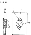
- the spacer 23 may be partially embedded into openings, which are perforated at the center position and the peripheral positions separate from the center position in the projecting member 21 on which a plurality of projections are arranged in a lozenge shape, as shown in Fig. 22.
- the projecting member 21 and the spacer 23 can be easily combined without adhering thereamong.
- only the spacer 23 in the center opening or only the spacers 23 in the peripheral openings can be utilized.
- the spacer 23 having a plurality of cylindrical portions may be utilized. And the cylindrical portions 23 are inserted into openings formed in the projecting member 21 from the hinder surface of the base portion 22. By this construction, the projecting member 21 and the spacers 23 can be easily combined.
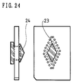
- the spacer 23 with a contacting portion 24 having a wedge shape, the contacting portion 24 being contacted with the print medium P may be used. And such contact portion 24 is inserted into openings formed in the projecting member 21.
- the contacting portion 24 the wedge shape as shown in Fig. 24 the print medium P can be smoothly guided into the printer without being stopped by the projections when the print medium P is fed into the printer.
- the relationship between the spacer and the projections is suitably determined based on the distance between the projections and the molderbility of the spacer.
Landscapes
- Handling Of Sheets (AREA)
Applications Claiming Priority (4)
| Application Number | Priority Date | Filing Date | Title |
|---|---|---|---|
| JP276037/92 | 1992-10-14 | ||
| JP27603792 | 1992-10-14 | ||
| JP114918/93 | 1993-05-17 | ||
| JP11491893A JPH06179271A (ja) | 1992-10-14 | 1993-05-17 | シリアルインパクトプリンタ |
Publications (2)
| Publication Number | Publication Date |
|---|---|
| EP0593293A2 true EP0593293A2 (de) | 1994-04-20 |
| EP0593293A3 EP0593293A3 (de) | 1995-03-08 |
Family
ID=26453564
Family Applications (1)
| Application Number | Title | Priority Date | Filing Date |
|---|---|---|---|
| EP93308194A Withdrawn EP0593293A3 (de) | 1992-10-14 | 1993-10-14 | Serieller Stossdrucker. |
Country Status (2)
| Country | Link |
|---|---|
| EP (1) | EP0593293A3 (de) |
| JP (1) | JPH06179271A (de) |
Cited By (1)
| Publication number | Priority date | Publication date | Assignee | Title |
|---|---|---|---|---|
| EP1093927A1 (de) * | 1999-10-18 | 2001-04-25 | COMPUPRINT S.p.A. | Ebenes lärmschutzdruckwiderlager für anschlagdrucker |
Family Cites Families (2)
| Publication number | Priority date | Publication date | Assignee | Title |
|---|---|---|---|---|
| US5066150A (en) * | 1990-04-18 | 1991-11-19 | Xerox Corporation | Low cost quiet impact printer |
| EP0605098A3 (de) * | 1992-11-12 | 1994-12-07 | Brother Ind Ltd | Serieller Anschlagdrucker. |
-
1993
- 1993-05-17 JP JP11491893A patent/JPH06179271A/ja active Pending
- 1993-10-14 EP EP93308194A patent/EP0593293A3/de not_active Withdrawn
Cited By (2)
| Publication number | Priority date | Publication date | Assignee | Title |
|---|---|---|---|---|
| EP1093927A1 (de) * | 1999-10-18 | 2001-04-25 | COMPUPRINT S.p.A. | Ebenes lärmschutzdruckwiderlager für anschlagdrucker |
| US6588955B1 (en) | 1999-10-18 | 2003-07-08 | Compuprint Spa | Anti-noise platen of the flat type for an impact printer |
Also Published As
| Publication number | Publication date |
|---|---|
| JPH06179271A (ja) | 1994-06-28 |
| EP0593293A3 (de) | 1995-03-08 |
Similar Documents
| Publication | Publication Date | Title |
|---|---|---|
| EP0728589B1 (de) | Aufzeichnungsgerät | |
| US20060163803A1 (en) | Feeding Device And Image Recording Apparatus Equipped With The Feeding Device | |
| US6129461A (en) | Image recording apparatus having adjustment structure | |
| EP0058902B1 (de) | Schalldämmende Einrichtung für einen seriellen Anschlagdrucker | |
| EP0593293A2 (de) | Serieller Stossdrucker | |
| US7618139B2 (en) | Printer having improved recording medium feeding mechanism | |
| JPH08332752A (ja) | サーマルラインプリンタ | |
| US5425588A (en) | Pivoting platen for use in printing device | |
| JP4484055B2 (ja) | 搬送装置及びそれを備えた画像記録装置 | |
| JPS62187063A (ja) | プリンタのヘツド間隙自動調整機構 | |
| US4967662A (en) | High speed printer with interposer | |
| US5344246A (en) | Printer having a vibrating platen | |
| US7331728B2 (en) | Printer having a platen | |
| EP0794063B1 (de) | Tintenstrahldrucker | |
| EP4299325B1 (de) | Druckeinheit und tragbares endgerät | |
| EP1004529B1 (de) | Rollenzuführgerät für ein Drucksubstrat mit nicht-einheitlicher Dicke | |
| JPH07100394B2 (ja) | 通帳類印字装置 | |
| EP0263869B1 (de) | Druckkopfwagen | |
| JP2944584B2 (ja) | カードガイド機構 | |
| JPH03101986A (ja) | サーマルプリンタ | |
| JP2002220147A (ja) | 記録装置 | |
| JP2706581B2 (ja) | 画像形成装置 | |
| JPS6324475B2 (de) | ||
| JPH06127043A (ja) | シリアルインパクトプリンタ | |
| JP3904070B2 (ja) | ドットプリンタ |
Legal Events
| Date | Code | Title | Description |
|---|---|---|---|
| PUAI | Public reference made under article 153(3) epc to a published international application that has entered the european phase |
Free format text: ORIGINAL CODE: 0009012 |
|
| AK | Designated contracting states |
Kind code of ref document: A2 Designated state(s): DE GB |
|
| PUAL | Search report despatched |
Free format text: ORIGINAL CODE: 0009013 |
|
| AK | Designated contracting states |
Kind code of ref document: A3 Designated state(s): DE GB |
|
| 18D | Application deemed to be withdrawn |
Effective date: 19950909 |