EP0593041B1 - Tintenstrahlaufzeichnungsvorrichtung - Google Patents
Tintenstrahlaufzeichnungsvorrichtung Download PDFInfo
- Publication number
- EP0593041B1 EP0593041B1 EP93116574A EP93116574A EP0593041B1 EP 0593041 B1 EP0593041 B1 EP 0593041B1 EP 93116574 A EP93116574 A EP 93116574A EP 93116574 A EP93116574 A EP 93116574A EP 0593041 B1 EP0593041 B1 EP 0593041B1
- Authority
- EP
- European Patent Office
- Prior art keywords
- resistor element
- recording head
- ink
- resistance value
- ink jet
- Prior art date
- Legal status (The legal status is an assumption and is not a legal conclusion. Google has not performed a legal analysis and makes no representation as to the accuracy of the status listed.)
- Expired - Lifetime
Links
- 238000007599 discharging Methods 0.000 claims description 49
- 238000010438 heat treatment Methods 0.000 claims description 22
- 238000000034 method Methods 0.000 claims description 22
- 230000008569 process Effects 0.000 claims description 19
- 238000004519 manufacturing process Methods 0.000 claims description 12
- 230000000087 stabilizing effect Effects 0.000 claims description 11
- 230000004044 response Effects 0.000 claims description 5
- 238000009434 installation Methods 0.000 claims 2
- 239000000976 ink Substances 0.000 description 71
- 239000000758 substrate Substances 0.000 description 37
- 239000007788 liquid Substances 0.000 description 18
- 238000012545 processing Methods 0.000 description 11
- 238000010276 construction Methods 0.000 description 10
- 238000010586 diagram Methods 0.000 description 9
- 238000004140 cleaning Methods 0.000 description 8
- 229910052710 silicon Inorganic materials 0.000 description 6
- 239000010703 silicon Substances 0.000 description 6
- XUIMIQQOPSSXEZ-UHFFFAOYSA-N Silicon Chemical compound [Si] XUIMIQQOPSSXEZ-UHFFFAOYSA-N 0.000 description 5
- 230000000694 effects Effects 0.000 description 5
- 238000011084 recovery Methods 0.000 description 5
- 230000009471 action Effects 0.000 description 4
- 239000011159 matrix material Substances 0.000 description 4
- 230000004048 modification Effects 0.000 description 4
- 238000012986 modification Methods 0.000 description 4
- 230000005540 biological transmission Effects 0.000 description 3
- 238000009835 boiling Methods 0.000 description 3
- 230000008859 change Effects 0.000 description 3
- 239000002131 composite material Substances 0.000 description 3
- 230000006866 deterioration Effects 0.000 description 3
- 230000006870 function Effects 0.000 description 3
- 238000004806 packaging method and process Methods 0.000 description 2
- 239000007787 solid Substances 0.000 description 2
- 238000003860 storage Methods 0.000 description 2
- XAGFODPZIPBFFR-UHFFFAOYSA-N aluminium Chemical compound [Al] XAGFODPZIPBFFR-UHFFFAOYSA-N 0.000 description 1
- 229910052782 aluminium Inorganic materials 0.000 description 1
- 239000000470 constituent Substances 0.000 description 1
- 230000006378 damage Effects 0.000 description 1
- 238000004090 dissolution Methods 0.000 description 1
- 239000000428 dust Substances 0.000 description 1
- 238000001704 evaporation Methods 0.000 description 1
- 230000008020 evaporation Effects 0.000 description 1
- 239000011521 glass Substances 0.000 description 1
- 230000006872 improvement Effects 0.000 description 1
- 230000010365 information processing Effects 0.000 description 1
- 238000003780 insertion Methods 0.000 description 1
- 230000037431 insertion Effects 0.000 description 1
- 238000005259 measurement Methods 0.000 description 1
- 238000005192 partition Methods 0.000 description 1
- 239000011347 resin Substances 0.000 description 1
- 229920005989 resin Polymers 0.000 description 1
- 230000000717 retained effect Effects 0.000 description 1
- 150000003376 silicon Chemical class 0.000 description 1
- 239000000126 substance Substances 0.000 description 1
Images


Classifications
-
- B—PERFORMING OPERATIONS; TRANSPORTING
- B41—PRINTING; LINING MACHINES; TYPEWRITERS; STAMPS
- B41J—TYPEWRITERS; SELECTIVE PRINTING MECHANISMS, i.e. MECHANISMS PRINTING OTHERWISE THAN FROM A FORME; CORRECTION OF TYPOGRAPHICAL ERRORS
- B41J2/00—Typewriters or selective printing mechanisms characterised by the printing or marking process for which they are designed
- B41J2/005—Typewriters or selective printing mechanisms characterised by the printing or marking process for which they are designed characterised by bringing liquid or particles selectively into contact with a printing material
- B41J2/01—Ink jet
- B41J2/015—Ink jet characterised by the jet generation process
- B41J2/04—Ink jet characterised by the jet generation process generating single droplets or particles on demand
- B41J2/045—Ink jet characterised by the jet generation process generating single droplets or particles on demand by pressure, e.g. electromechanical transducers
- B41J2/04501—Control methods or devices therefor, e.g. driver circuits, control circuits
- B41J2/04506—Control methods or devices therefor, e.g. driver circuits, control circuits aiming at correcting manufacturing tolerances
-
- B—PERFORMING OPERATIONS; TRANSPORTING
- B41—PRINTING; LINING MACHINES; TYPEWRITERS; STAMPS
- B41J—TYPEWRITERS; SELECTIVE PRINTING MECHANISMS, i.e. MECHANISMS PRINTING OTHERWISE THAN FROM A FORME; CORRECTION OF TYPOGRAPHICAL ERRORS
- B41J2/00—Typewriters or selective printing mechanisms characterised by the printing or marking process for which they are designed
- B41J2/005—Typewriters or selective printing mechanisms characterised by the printing or marking process for which they are designed characterised by bringing liquid or particles selectively into contact with a printing material
- B41J2/01—Ink jet
- B41J2/015—Ink jet characterised by the jet generation process
- B41J2/04—Ink jet characterised by the jet generation process generating single droplets or particles on demand
- B41J2/045—Ink jet characterised by the jet generation process generating single droplets or particles on demand by pressure, e.g. electromechanical transducers
- B41J2/04501—Control methods or devices therefor, e.g. driver circuits, control circuits
- B41J2/04528—Control methods or devices therefor, e.g. driver circuits, control circuits aiming at warming up the head
-
- B—PERFORMING OPERATIONS; TRANSPORTING
- B41—PRINTING; LINING MACHINES; TYPEWRITERS; STAMPS
- B41J—TYPEWRITERS; SELECTIVE PRINTING MECHANISMS, i.e. MECHANISMS PRINTING OTHERWISE THAN FROM A FORME; CORRECTION OF TYPOGRAPHICAL ERRORS
- B41J2/00—Typewriters or selective printing mechanisms characterised by the printing or marking process for which they are designed
- B41J2/005—Typewriters or selective printing mechanisms characterised by the printing or marking process for which they are designed characterised by bringing liquid or particles selectively into contact with a printing material
- B41J2/01—Ink jet
- B41J2/015—Ink jet characterised by the jet generation process
- B41J2/04—Ink jet characterised by the jet generation process generating single droplets or particles on demand
- B41J2/045—Ink jet characterised by the jet generation process generating single droplets or particles on demand by pressure, e.g. electromechanical transducers
- B41J2/04501—Control methods or devices therefor, e.g. driver circuits, control circuits
- B41J2/04565—Control methods or devices therefor, e.g. driver circuits, control circuits detecting heater resistance
-
- B—PERFORMING OPERATIONS; TRANSPORTING
- B41—PRINTING; LINING MACHINES; TYPEWRITERS; STAMPS
- B41J—TYPEWRITERS; SELECTIVE PRINTING MECHANISMS, i.e. MECHANISMS PRINTING OTHERWISE THAN FROM A FORME; CORRECTION OF TYPOGRAPHICAL ERRORS
- B41J2/00—Typewriters or selective printing mechanisms characterised by the printing or marking process for which they are designed
- B41J2/005—Typewriters or selective printing mechanisms characterised by the printing or marking process for which they are designed characterised by bringing liquid or particles selectively into contact with a printing material
- B41J2/01—Ink jet
- B41J2/015—Ink jet characterised by the jet generation process
- B41J2/04—Ink jet characterised by the jet generation process generating single droplets or particles on demand
- B41J2/045—Ink jet characterised by the jet generation process generating single droplets or particles on demand by pressure, e.g. electromechanical transducers
- B41J2/04501—Control methods or devices therefor, e.g. driver circuits, control circuits
- B41J2/0458—Control methods or devices therefor, e.g. driver circuits, control circuits controlling heads based on heating elements forming bubbles
-
- B—PERFORMING OPERATIONS; TRANSPORTING
- B41—PRINTING; LINING MACHINES; TYPEWRITERS; STAMPS
- B41J—TYPEWRITERS; SELECTIVE PRINTING MECHANISMS, i.e. MECHANISMS PRINTING OTHERWISE THAN FROM A FORME; CORRECTION OF TYPOGRAPHICAL ERRORS
- B41J2/00—Typewriters or selective printing mechanisms characterised by the printing or marking process for which they are designed
- B41J2/005—Typewriters or selective printing mechanisms characterised by the printing or marking process for which they are designed characterised by bringing liquid or particles selectively into contact with a printing material
- B41J2/01—Ink jet
- B41J2/015—Ink jet characterised by the jet generation process
- B41J2/04—Ink jet characterised by the jet generation process generating single droplets or particles on demand
- B41J2/045—Ink jet characterised by the jet generation process generating single droplets or particles on demand by pressure, e.g. electromechanical transducers
- B41J2/04501—Control methods or devices therefor, e.g. driver circuits, control circuits
- B41J2/0459—Height of the driving signal being adjusted
-
- B—PERFORMING OPERATIONS; TRANSPORTING
- B41—PRINTING; LINING MACHINES; TYPEWRITERS; STAMPS
- B41J—TYPEWRITERS; SELECTIVE PRINTING MECHANISMS, i.e. MECHANISMS PRINTING OTHERWISE THAN FROM A FORME; CORRECTION OF TYPOGRAPHICAL ERRORS
- B41J2/00—Typewriters or selective printing mechanisms characterised by the printing or marking process for which they are designed
- B41J2/005—Typewriters or selective printing mechanisms characterised by the printing or marking process for which they are designed characterised by bringing liquid or particles selectively into contact with a printing material
- B41J2/01—Ink jet
- B41J2/015—Ink jet characterised by the jet generation process
- B41J2/04—Ink jet characterised by the jet generation process generating single droplets or particles on demand
- B41J2/045—Ink jet characterised by the jet generation process generating single droplets or particles on demand by pressure, e.g. electromechanical transducers
- B41J2/04501—Control methods or devices therefor, e.g. driver circuits, control circuits
- B41J2/04591—Width of the driving signal being adjusted
Definitions
- the present invention relates to an ink jet recording apparatus, and more particularly to a construction of an ink jet recording head including a resistor element, the resistor element generating thermal energy utilized for discharging ink.
- EP 0 376 314 discloses a liquid jet recording apparatus.
- a recording head is provided with an integral temperature sensor.
- the temperature controlling operation is performed in response to an output of the temperature sensor to maintain the recording liquid within a predetermined temperature range.
- the main apparatus contains a reference temperature sensor.
- the temperature sensor of the recording head is corrected in its output on the basis of a comparison between the temperature sensors.
- the recording head is provided with information representative of a property of the temperature sensor of the recording head. By the mounting of the recording head into the apparatus, the information is read, and the output of the temperature sensor is corrected on the basis of the read information.
- US 4,872,027 describes a dot-matrix printer provided with different types of printheads which are interchangeably attachable to the printer carriage.
- the heads are provided with individual codes which are read by the printer control system and used to reconfigure its control function to suit the control requirements of the identified head.
- Such a system may include a microprocessor responsive to individual sets of instructions or programs providing new and different processing capabilities for printing control in response to the insertion of a new printhead.
- the ink jet recording apparatus may have a construction which enables a recording head unit of cartridge-type in which a recording head is integrated with an ink tank to be exchanged at a time when ink in the ink tank is completely consumed.
- a process for measuring a threshold voltage V th that is, a lowest voltage of the heating resistor element at which ink discharge actually just occurs and a process for storing measured results as data into a memory circuit provided, for example, at a printed board of the recording head. Then, the stored data in this process are read out by means of a control portion of an ink jet recording apparatus on which the recording head is installed, and in response to the read out data the driving voltage of the heating resistor element can be set up.
- a process for stabilizing ink discharge of the recording head is that: before shipping of the recording head certain pulses of a driving voltage K times as much as the threshold driving voltage V th measured in the measuring process described above is applied a plurality of times to each of the heating resistor elements so as to stabilize ink discharging characteristic of the recording head.
- a problem similar to that in the conventional process described above in the item 2) arises in a construction other than the construction in which a plurality of information signals are held in the recording head.
- the problem arises in a case where heating resistor elements used for temperature control of the recording head are disposed thereto. This problem will be described below in detail with reference to Figs. 1 and 2.
- Fig. 1 is a schematic view showing a construction on a substrate 1101.
- a heating resistor element hereafter, a heating resistor element is referred to as a discharging heater
- a discharging heater which correspond to a plurality of discharging orifices of the recording head, respectively, are arranged at near one end side thereof (portion near an upper end side in the figure) and a resistor element group 1107 is formed with those discharging heaters.
- Each of discharging heaters in the resistor element group 1107 is driven by a driver 1109 in accordance with a respective heater driving signal via matrix arrayed wiring 1108, whereby heat is applied to ink and discharge of the ink is performed.
- Resistor elements hereafter, a resistor element is referred to as a sub-heater
- Resistor elements 1103 and 1104 are disposed at near both side ends of the substrate 1101 (portions near each of left and right sides thereof in the figure), respectively, the resistor elements 1103 and 1104 being used for heating in the temperature control of the recording head.
- a grounding terminal 1105, an input terminal 1106 for heater driving signal, and an electric power supply terminal 1110 are provided at near the other end side in the substrate 1101 (a portion near a lower end side thereof in the figure), and further are provided two terminals 1102a, 1102a for the sub-heater 1103 and two terminals 1102b, 1102b for the sub-heater 1104, respectively.
- respective four contacting portions to be connected physically are connected in such a manner that: the contacting portion between the substrate 1101 and the printed wiring board 1303 is connected by bonding wires 1302; the contacting portion between the printed wiring board 1303 and a flexible plate (flexible cable) 1305 is connected by a pressure contacting portion 1304, and the flexible plate 1305 and a main electric component mounting plate 1307 of the recording apparatus is connected by pressure contacting using a connector 1306, respectively.
- An object of the present invention is to provide a recording head and an ink jet recording apparatus using the recording head, by which it enables to dissolve the problems related to the set up of the driving voltage of the discharging heater and the discharge stabilizing processing as described above and at the same time to dissolve the deterioration of the reliability or the like which are derived from the dissolution of the above two problems.
- Another object of the present invention is to provide an ink jet recording apparatus which enables to determine the driving electric power of a discharging resistor element on the basis of the resistance value of the other resistor element which is provided in the same process as the discharging resistor element as described above of a recording head installed on the ink jet recording apparatus.
- Still another object of the present invention is to provide a recording head and an ink jet recording apparatus, in which by connecting one terminal of respective resistor elements included in a recording head to a grounding terminal of the recording head or an electric power supply terminal, the number of leads drawn out from the resistor elements can be reduced, whereby the improvement of the reliability of contact portions and the lowering of manufacturing cost thereof can be realized.
- Still another object of the present invention is to provide a recording head and an ink jet recording apparatus in which the set up of the driving power of the discharging heater can be performed without actual discharge of ink which may be affected by dust on the discharging heater or the like.
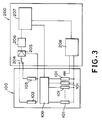
- Fig. 3 is a block diagram showing a structure for driving a heating resistance element in an ink-jet recording apparatus of an embodiment according to the present invention.
- a plurality of heating resistance elements 101 (referred to below as a discharging heater) for generating thermal energy are formed which correspond to a plurality of ink discharging orifices, respectively.
- a driving circuit 109 for generating thermal energy.
- two resistance elements 102 and 103 are formed, which are formed by the same process as that for the discharging heater 101 and whose resistance values are measurable. As described later, these resistance values are read by an apparatus 200 according to the switching of a switch 204 of the apparatus 200.
- a DC amplifier 205 for amplifying a signal from the detecting heater 102 or 103 and an A/D converter 206 for analog-to-digital converting a signal from the DC amplifier.
- a logic circuit 207 determines the driving condition of the discharging heater 101 on the basis of a signal of a resistance value from the A/D converter 206.
- Reference numeral 208 denotes a power supply source for driving the discharging heater 101.
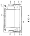
- Fig. 4 is a schematic plan view showing a portion to which electric power is supplied in the substrate 100 of Fig. 3.
- a matrix arranged wiring 111 is connected to the plurality of discharging heaters 101 to drive the plurality of the discharging heaters selectively on the basis of the data on discharging.
- a group of connecting pads 116 is connected to edge portions of the matrix wiring 111.
- Wires 112 and 113 for supplying electric power to the detecting heaters 102 and 103 are connected to the detecting heaters 102 and 103, respectively, and terminals 122, 122 and 123, 123 are connected to the edge portions of the wires 112 and 113, respectively.
- Fig. 5 is a block diagram showing an electrical connection schematically when a recording head 1 is mounted on the ink-jet recording apparatus 200.
- the recording head 1 is connected to an electrical packaging substrate 307 via a flexible cable 305.
- the flexible cable 305 is connected to the electrical packaging substrate 307 through a connector 306, and the recording head 1 is connected to the flexible cable 305 through a connection under pressure.
- the electrical structure of the recording head 1 is composed of the substrate 100 and a printed circuit board 303 and the substrate 100 is connected to the printed circuit board 303 through wire bonding 302.
- the logic circuit 207 reads the resistance values of the detecting heaters 102 and 103 in sequence in accordance with changeover of the switch 204.
- the reason for reading both of these resistance values is as follows.
- the logic circuit 207 sets the heater driving voltage according to a predetermined relationship between the read resistance values and the heater driving voltage, and these setting enables an applying this set driving voltage to the heater 101.
- the resistance value of wire 113 of the detecting heater is r sub [ ⁇ ]
- the heater power for a unit area necessary for starting discharging ink by the discharging heater 101 is P H [J/ ⁇ m 2 ]
- width and length of the heater 101 are W[ ⁇ m] and l[ ⁇ m] respectively
- a resistance value of the wire 111 connected to the heater 101 is r H [ ⁇ ]
- an applied threshold voltage necessary for starting discharging ink is V th [V] and pulse width of a driving pulse at this time is P W [s]
- the threshold voltage V th [V] is given by the following formula:
- the driving voltage of the discharging heater 101 is set to a value 1.2 times as much as the threshold voltage V th .
- the reason for setting these value is that durability against destruction caused by heating stress on the heater 101 and a margin for discharging ink are considered. That is, when a voltage larger than the above set voltage is applied to the heater 101, lifetime of the heater 101 is shortened compared with standard rating lifetime. To the contrary, when a voltage smaller than the above set voltage is applied to the heater 101, unstable discharge of ink such as non-discharge occurs and recording quality is deteriorated.
- the above setting is performed on the basis of the resistance value Rsub of the detecting heater 102 and 103 read in the logic circuit of the recording apparatus 200 and the set driving voltage is applied to the discharging heater 101 via the power supply source 208.
- the driving voltage in the discharge stabilizing processing to be performed before shipment of the recording head after it has been manufactured is set similarly to the above.
- the discharge stabilizing processing is performed in such manner that pulses with predetermined voltage number of which is of 10 4 to 10 8 is applied to each of discharging heaters 101 and then ink are discharged.
- pulses with predetermined voltage number of which is of 10 4 to 10 8 is applied to each of discharging heaters 101 and then ink are discharged.
- the driving voltage is not limited to the above value. Even though the driving voltage is set to a value 1 to 1.8 times as much as the threshold voltage V th in the discharge stabilizing processing, the good discharge stabilizing processing can be obtained.
- the detecting heaters 102 and 103 may be provided so that the resistance value thereof is only read as described above, but may be a heater for heating the recording head or a resistance element for detecting temperatures used for controlling temperatures of the recording head. Furthermore, a resistance value of part of the discharging heater 101 may be read without separately providing the detecting heater for only reading the resistance value thereof as described above.
- the resistance value of the detecting heater which is read at when the recording head is mounted, may also include resistance values of a wire of the detecting heater and a driving IC.
- a more correct driving voltage can be set by setting the threshold voltage V th on the basis of a resistance value obtained by subtracting the resistance value of the driving IC from the read resistance value of the detecting heater.
- an appropriate heater driving voltage is set on the basis of the read resistance value.
- the setting of the heater driving voltage is not limited thereto, and instead, pulse width may be set.
- the pulse width in turn, becomes the function of the resistor value of the detecting heater and is calculated through a modified equation of the above stated equation.
- the driving voltage is set on the basis of the measured resistance value of the detecting heater, whereby:
- embodiment 2 relates to the structure in which the number of connecting terminals on the substrate is further reduced to increase the reliability of contact portions, when the detecting heater is disposed on the recording head as described in the above embodiment 1.
- embodiment 2 may be applied not only to a recording head with a detecting heater provided but also to a recording head with a heating sub-heater for controlling temperatures of a recording head or a resistance element for detecting temperatures provided.
- Fig. 6 is an explanatory view for illustrating a schematic structure of layout on a silicon substrate 100 of a recording head of a second embodiment according to the present invention.
- the substrate 100 On the substrate 100, there are provided the above stated detecting heaters 102 and 103, a discharging heater 101, a heater driver 109, a wire 108 connected between the discharging heater 101 and a heater driver 109 and a heater driving signal input pad 116.
- ground terminals 105a, 105b and power supplying terminals 110a, 110b are formed in either edge portion of the substrate 100.
- One end of the detecting heater 102 is connected to a monitor terminal 132, one ends of detecting heaters 102 and 103 are connected to each other through the connecting portion 131, and the other end of the detecting heater 103 is connected to the ground terminal 105b.
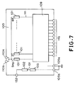
- Fig. 7 is a block diagram of a circuit formed on the substrate 100 shown in Fig. 6.
- the detecting heaters 102 and 103 are connected in series between the monitor terminal 132 and the ground terminal 105b. Therefore, the change in a composite resistance of the detecting heaters 102 and 103 can be monitored between the terminals 132 and 105b. Providing a single wire connected to the monitor terminal 132 is enough to monitor the above change.
- the detecting heater instead of the detecting heater, when two resistance elements as temperature sensors are disposed in either edge portion of the silicon substrate 100 and are connected in series, average temperatures of either portion of the substrate 100 can be detected in consideration of variation in temperatures on the substrate 100. Moreover, when being disposed as a heating element, an active resistance element heats the substrate 100 so as to control the temperature of the substrate 100 appropriately.
- connection portions can be improved.
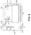
- Fig. 8 is a circuit block diagram for explaining a modification example of embodiment 2.
- detecting heaters 102 and 103 are connected in serial between the monitor terminal 132 and the power supply terminal 110b. Therefore, in this example, a composite resistance formed by connecting the detecting heaters 102 and 103 in serial between the terminals 132 and 110b, can be monitored.
- Fig. 9 is a circuit block diagram for explaining another modification example of embodiment 2.
- detecting heaters 102 and 103 are connected in parallel between the monitor terminal 132 and the ground terminal 105b. Therefore, in this example, a composite resistance formed by connecting the detecting heaters 102 and 103 in parallel between the terminals 132 and 105b, can be monitored.
- Fig. 10 is a partially cut away perspective view for showing a structure of a discharging portion of the recording head to which the above each embodiment can be applied.
- a recording head 510 has a structure in which a head chip and an ink storage portion are formed integrally.
- the head chip has a junction structure of a silicon substrate 100 and a glass or resinous top plate 504 and a plurality of discharging orifices 500 are formed in line on a discharging surface side in the junction portion.
- the plurality of discharging orifices 500 communicate with a common liquid chamber (liquid chamber) 504 via a plurality of liquid paths 505, respectively.
- a partition 501 between the two liquid paths 505 is formed by ultraviolet setting resin etc., for example.
- the common liquid chamber 504 communicates with the ink storage portion via a tube 503.
- a discharging heater 101 as a heat energy generating element which is disposed in each of the plurality of liquid paths 505 and a wire 111 made of aluminum etc. for supplying electric power to each discharging heater 101 are formed using the film-forming technique.
- the above described detecting heaters 102 and 103 are also disposed on the substrate 100.
- Fig. 11 is a schematic view of an ink-jet recording apparatus IJRA with the above recording head 510 provided.
- a lead screw 5005 turns in the forward or reverse direction with the forward or reverse turn of a driving motor 5013 via driving power transmission gears 5011 and 5009.
- a carriage HC having a pin (not shown) engaged with a spiral groove 5004 is reciprocated in the directions shown by arrows a and b.
- a recording head 510 is mounted on the carriage HC.
- Reference numeral 5002 denotes a sheet pressure plate which presses paper P against a platen 5000 over the moving range of the carriage HC.
- Reference numerals 5007 and 5008 denote photo-couplers, or detecting means for detecting a home position, which confirm presence of a lever of the carriage HC so as to switch the rotational direction of the motor 5013.
- Reference numeral 5016 denotes a member for supporting a cap member 5022 which caps a front surface of the recording head 510.
- Reference numeral 5015 denotes suction means for sucking the inside of the cap member 5022, which performs suction recovery of the recording head 510 via an opening 5023 of the cap member 5022.
- Reference numerals 5017 and 5019 denote a cleaning blade and a member which enables the cleaning blade to move forward and backward, and they are supported by an apparatus supporting plate 5018. With the cleaning blade 5017, it is needless to say that a well known cleaning blade other than the above cleaning blade can be applied to this embodiment.
- reference numeral 5012 denotes a lever, which moves with movement of a cam 5020 engaged with the carriage HC, and the driving force transmitted from the driving motor 5013 is moved and controlled by well known transmission means such as clutch switchover means.
- capping, cleaning and suction recovery actions are constructed so that these actions can perform desired processing at the corresponding positions by an action of the lead screw 5005 when the carriage HC arrives at the home position area.
- these capping, cleaning and suction recovery actions are applicable to any one of the embodiments of the present invention.
- the above each structure is a superior invention from a viewpoint of a single structure and combined structures and shows a preferable structural embodiment.
- the present invention achieves distinct effect when applied to a recording head or a recording apparatus which has means for generating thermal energy such as electrothermal transducers or laser light, and which causes changes in ink by the thermal energy so as to eject ink. This is because such a system can achieve a high density and high resolution recording.
- the on-demand type apparatus has electrothermal transducers, each disposed on a sheet or liquid passage that retains liquid (ink), and operates as follows: first, one or more drive signals are applied to the electrothermal transducers to cause thermal energy corresponding to recording information; second, the thermal energy induces sudden temperature rise that exceeds the nucleate boiling so as to cause the film boiling on heating portions of the recording head; and third, bubbles are grown in the liquid (ink) corresponding to the drive signals. By using the growth and collapse of the bubbles, the ink is expelled from at least one of the ink ejection orifices of the head to form one or more ink drops.
- the drive signal in the form of a pulse is preferable because the growth and collapse of the bubbles can be achieved instantaneously and suitably by this form of drive signal.
- a drive signal in the form of a pulse those described in U.S. patent Nos. 4,463,359 and 4,345,262 are preferable.
- the rate of temperature rise of the heating portions described in U.S. patent No. 4,313,124 be adopted to achieve better recording.
- U.S. patent Nos. 4,558,333 and 4,459,600 disclose the following structure of a recording head, which is incorporated to the present invention: this structure includes heating portions disposed on bent portions in addition to a combination of the ejection orifices, liquid passages and the electrothermal transducers disclosed in the above patents. Moreover, the present invention can be applied to structures disclosed in Japanese Patent Application Laying-open Nos. 123670/1984 and 138461/1984 in order to achieve similar effects.
- the former discloses a structure in which a slit common to all the electrothermal transducers is used as ejection orifices of the electrothermal transducers, and the latter discloses a structure in which openings for absorbing pressure waves caused by thermal energy are formed corresponding to the ejection orifices.
- the present invention can be also applied to a so-called full-line type recording head whose length equals the maximum length across a recording medium.
- a recording head may consists of a plurality of recording heads combined together, or one integrally arranged recording head.
- the present invention can be applied to various serial type recording heads: a recording head fixed to the main assembly of a recording apparatus; a conveniently replaceable chip type recording head which, when loaded on the main assembly of a recording apparatus, is electrically connected to the main assembly, and is supplied with ink therefrom; and a cartridge type recording head integrally including an ink reservoir.
- a recovery system or a preliminary auxiliary system for a recording head as a constituent of the recording apparatus because they serve to make the effect of the present invention more reliable.
- the recovery system are a capping means and a cleaning means for the recording head, and a pressure or suction means for the recording head.
- the preliminary auxiliary system are a preliminary heating means utilizing electrothermal transducers or a combination of other heater elements and the electrothermal transducers, and a means for carrying out preliminary ejection of ink independently of the ejection for recording. These systems are effective for reliable recording.
- the number and type of recording heads to be mounted on a recording apparatus can be also changed. For example, only one recording head corresponding to a single color ink, or a plurality of recording heads corresponding to a plurality of inks different in color or concentration can be used.
- the present invention can be effectively applied to an apparatus having at least one of the monochromatic, multi-color and full-color modes.
- the monochromatic mode performs recording by using only one major color such as black.
- the multi-color mode carries out recording by using different color inks, and the full-color mode performs recording by color mixing.
- inks that are liquid when the recording signal is applied can be used: for example, inks can be employed that solidify at a temperature lower than the room temperature and are softened or liquefied in the room temperature. This is because in the ink jet system, the ink is generally temperature adjusted in a range of 30°C - 70°C so that the viscosity of the ink is maintained at such a value that the ink can be ejected reliably.
- the present invention can be applied to such apparatus where the ink is liquefied just before the ejection by the thermal energy as follows so that the ink is expelled from the orifices in the liquid state, and then begins to solidify on hitting the recording medium, thereby preventing the ink evaporation: the ink is transformed from solid to liquid state by positively utilizing the thermal energy which would otherwise cause the temperature rise; or the ink, which is dry when left in air, is liquefied in response to the thermal energy of the recording signal.
- the ink may be retained in recesses or through holes formed in a porous sheet as liquid or solid substances so that the ink faces the electrothermal transducers as described in Japanese Patent Application Laying-open Nos. 56847/1979 or 71260/1985.
- the present invention is most effective when it uses the film boiling phenomenon to expel the ink.
- the ink jet recording apparatus of the present invention can be employed not only as an image output terminal of an information processing device such as a computer, but also as an output device of a copying machine including a reader, and as an output device of a facsimile apparatus having a transmission and receiving function.
- a driving voltage of a discharging heater in an ink jet recording head is set according to property of the individual recording head. More specifically, sub-heaters (102, 103) are formed on a board on which discharging heaters (101) are formed, by a same process as that for the discharging heaters. Resistance values of the sub-heaters (102, 103) are read so that the driving voltage of the discharging heaters (101) can be set on the basis of the read resistance values.
Landscapes
- Particle Formation And Scattering Control In Inkjet Printers (AREA)
- Ink Jet (AREA)
Claims (8)
- Eine Tintenstrahlaufzeichnungsvorrichtung zum Ausführen des Aufzeichnens durch Verwendung eines Aufzeichnungskopfs (100) zur Ausgabe von Tinte auf ein Aufzeichnungsmedium, miteinem ersten Widerstandselement (101), das in dem Aufzeichnungskopf ausgebildet und zum Erzeugen thermischer Energie vorgesehen ist, die zur Ausgabe der Tinte verwendet wird,einem zweiten Widerstandselement (102, 103), das in dem Aufzeichnungskopf durch das gleiche Verfahren wie das des ersten Widerstandselements ausgebildet ist,einem Lesemittel (207) zum Lesen eines Widerstandswerts des zweiten Widerstandselements in Antwort auf einen Anschluss des Aufzeichnungskopfs auf der Tintenstrahlaufzeichnungsvorrichtung,einem Einstellmittel (207) zum Berechnen eines Widerstandswerts des ersten Widerstandselements basierend auf dem Widerstandswert des zweiten Widerstandselements, der durch das Lesemittel gelesen wird, und zum Einstellen einer Antriebsenergie des ersten Widerstandselements auf der Grundlage des ausgerechneten Widerstandswerts des ersten Widerstandselements, undeinem Antriebsmittel (109) zum Zuführen der durch das Einstellmittel eingestellten Antriebsenergie zu dem ersten Widerstandselement, um das erste Widerstandselement anzutreiben.
- Eine Tintenstrahlaufzeichnungsvorrichtung gemäß Anspruch 1, miteiner Leitung zum Verbinden eines Anschlusses des zweiten Widerstandselements mit einem Anschluss zum Erden des Aufzeichnungskopfs oder mit einem Energiezufuhranschluss des Aufzeichnungskopfs, und zum Verbinden des anderen Anschlusses des Widerstandselements mit einem Erfassungsanschluss des Aufzeichnungskopfs, wobei das Einstellmittel den Widerstandswert des zweiten Widerstandselements über den Anschluss zum Erden oder dem Energiezufuhranschluss und dem Erfassungsanschluss liest.
- Eine Tintenstrahlaufzeichnungsvorrichtung, wie in Anspruch 1 oder 2 beansprucht ist, dadurch gekennzeichnet, dass das Einstellen der Antriebsenergie durch Einstellen einer Spannung eines Impulses durchgeführt wird, die dem ersten Widerstandselement zugeführt wird.
- Eine Tintenstrahlaufzeichnungsvorrichtung, wie in Anspruch 1 oder 2 beansprucht ist, dadurch gekennzeichnet, dass das Einstellen der Antriebsenergie durch Einstellen einer Impulsbreite durchgeführt wird, die dem ersten Widerstandselement zugeführt wird.
- Eine Tintenstrahlaufzeichnungsvorrichtung, wie in einem der vorhergehenden Ansprüche beansprucht ist, dadurch gekennzeichnet, dass das zweite Widerstandselement zum Erfassen einer Temperatur des Aufzeichnungskopfs verwendet wird.
- Eine Tintenstrahlaufzeichnungsvorrichtung, wie in einem der vorhergehenden Ansprüche beansprucht ist, dadurch gekennzeichnet, dass das zweite Widerstandselement zum Erhitzen des Aufzeichnungskopfs verwendet wird.
- Eine Tintenstrahlaufzeichnungsvorrichtung, wie in einem der vorhergehenden Ansprüche beansprucht ist, dadurch gekennzeichnet, dass das zweite Widerstandselement ein Teil einer Vielzahl der ersten Widerstandselemente darstellt.
- Ein Verfahren zum Stabilisieren eines Ausgabezustands eines Aufzeichnungskopfs zur Ausgabe von Tinte, mit den Schritten,Herstellen des Aufzeichnungskopfs mit einem ersten Widerstandselement zum Erzeugen thermischer Energie, die zur Ausgabe von Tinte verwendet wird, und mit einem zweiten Widerstandselement, das durch das gleiche Verfahren wie das des ersten Widerstandselements ausgebildet ist,Lesen eines Widerstandswerts des zweiten Widerstandselements in Antwort auf einen Anschluss des Aufzeichnungskopfs,Rechnen eines Widerstandswerts des ersten Widerstandselements auf der Grundlage des Widerstandswerts des zweiten Widerstandselements,Einstellen der Antriebsenergie des ersten Widerstandselements auf der Grundlage des berechneten Widerstandswerts des ersten Widerstandselements, undZuführen von 10t Impulsen, wobei jeder eine Energie k fach, so hoch wie die eingestellte Antriebsenergie, hat, um Tinte auszugeben, wobei 1,0 ≤ k ≤ 1,8 und 4 ≤ t ≤ 8 ist.
Applications Claiming Priority (6)
| Application Number | Priority Date | Filing Date | Title |
|---|---|---|---|
| JP27716392 | 1992-10-15 | ||
| JP27716392A JP3160388B2 (ja) | 1992-10-15 | 1992-10-15 | インクジェット記録装置および該装置で用いられるインクジェット記録ヘッド |
| JP277163/92 | 1992-10-15 | ||
| JP4306907A JPH06155743A (ja) | 1992-11-17 | 1992-11-17 | 記録ヘッドおよび記録装置 |
| JP306907/92 | 1992-11-17 | ||
| JP30690792 | 1992-11-17 |
Publications (3)
| Publication Number | Publication Date |
|---|---|
| EP0593041A2 EP0593041A2 (de) | 1994-04-20 |
| EP0593041A3 EP0593041A3 (en) | 1995-08-30 |
| EP0593041B1 true EP0593041B1 (de) | 2000-05-10 |
Family
ID=26552282
Family Applications (1)
| Application Number | Title | Priority Date | Filing Date |
|---|---|---|---|
| EP93116574A Expired - Lifetime EP0593041B1 (de) | 1992-10-15 | 1993-10-13 | Tintenstrahlaufzeichnungsvorrichtung |
Country Status (8)
| Country | Link |
|---|---|
| US (1) | US5943069A (de) |
| EP (1) | EP0593041B1 (de) |
| KR (1) | KR0172194B1 (de) |
| CN (1) | CN1064005C (de) |
| AU (2) | AU4899693A (de) |
| CA (1) | CA2108302C (de) |
| DE (1) | DE69328603T2 (de) |
| MX (1) | MX9306402A (de) |
Families Citing this family (15)
| Publication number | Priority date | Publication date | Assignee | Title |
|---|---|---|---|---|
| JP3143549B2 (ja) | 1993-09-08 | 2001-03-07 | キヤノン株式会社 | 熱記録ヘッド用基体、該基体を用いたインクジェット記録ヘッド、インクジェットカートリッジ、インクジェット記録装置、及び記録ヘッドの駆動方法 |
| JPH08118641A (ja) | 1994-10-20 | 1996-05-14 | Canon Inc | インクジェットヘッド、インクジェットヘッドカートリッジ、インクジェット装置およびインクが再注入されたインクジェットヘッドカートリッジ用インク容器 |
| JPH08197732A (ja) | 1995-01-24 | 1996-08-06 | Canon Inc | 記録ヘッド及び該記録ヘッドを用いた記録装置 |
| IT1293885B1 (it) * | 1997-04-16 | 1999-03-11 | Olivetti Canon Ind Spa | Dispositivo e metodo per controllare l'energia fornita ad un resistore di emissione di una testina di stampa termica a getto di inchiostro e |
| AUPP702498A0 (en) * | 1998-11-09 | 1998-12-03 | Silverbrook Research Pty Ltd | Image creation method and apparatus (ART77) |
| KR100341115B1 (ko) * | 2000-03-30 | 2002-06-20 | 권문구 | 수가교 방식을 이용하여 피티씨 조성물의 피티씨 특성을제어하는 방법 |
| DE60108205T2 (de) | 2000-06-30 | 2006-03-23 | Canon K.K. | Tintenstrahlaufzeichnungskopf, sein Herstellungsverfahren, Tintenstrahlaufzeichnungsvorrichtung und Verfahren zum ansteuern eines Tintenstrahldruckkopfes |
| US6869157B2 (en) * | 2001-03-26 | 2005-03-22 | Canon Kabushiki Kaisha | Method of driving and controlling ink jet print head, ink jet print head, and ink jet printer |
| US6582045B2 (en) | 2001-04-27 | 2003-06-24 | Canon Kabushiki Kaisha | Printing apparatus and printing control method |
| JP3652321B2 (ja) * | 2001-05-08 | 2005-05-25 | キヤノン株式会社 | インクジェット記録ヘッド |
| US6976752B2 (en) * | 2003-10-28 | 2005-12-20 | Lexmark International, Inc. | Ink jet printer with resistance compensation circuit |
| US7168780B2 (en) * | 2004-02-02 | 2007-01-30 | Toshiba Tec Kabushiki Kaisha | Method of inspecting an inkjet head and the inspected inkjet head |
| US7871143B2 (en) * | 2004-06-30 | 2011-01-18 | Lexmark International, Inc. | Ground structure for temperature-sensing resistor noise reduction |
| JP4669278B2 (ja) * | 2004-12-27 | 2011-04-13 | キヤノン株式会社 | 記録ヘッド用素子基板、記録ヘッドおよび記録装置 |
| US20060176326A1 (en) * | 2005-02-09 | 2006-08-10 | Benq Corporation | Fluid injector devices and methods for utilizing the same |
Citations (1)
| Publication number | Priority date | Publication date | Assignee | Title |
|---|---|---|---|---|
| US4872027A (en) * | 1987-11-03 | 1989-10-03 | Hewlett-Packard Company | Printer having identifiable interchangeable heads |
Family Cites Families (20)
| Publication number | Priority date | Publication date | Assignee | Title |
|---|---|---|---|---|
| JPS53125586A (en) * | 1977-04-07 | 1978-11-01 | Sharp Corp | Temperature controller |
| CA1127227A (en) * | 1977-10-03 | 1982-07-06 | Ichiro Endo | Liquid jet recording process and apparatus therefor |
| US4330787A (en) * | 1978-10-31 | 1982-05-18 | Canon Kabushiki Kaisha | Liquid jet recording device |
| US4345262A (en) * | 1979-02-19 | 1982-08-17 | Canon Kabushiki Kaisha | Ink jet recording method |
| US4463359A (en) * | 1979-04-02 | 1984-07-31 | Canon Kabushiki Kaisha | Droplet generating method and apparatus thereof |
| US4313124A (en) * | 1979-05-18 | 1982-01-26 | Canon Kabushiki Kaisha | Liquid jet recording process and liquid jet recording head |
| JPS5656847A (en) * | 1979-10-16 | 1981-05-19 | Dainippon Printing Co Ltd | Manufacture of baggin box with extracting valve |
| US4558333A (en) * | 1981-07-09 | 1985-12-10 | Canon Kabushiki Kaisha | Liquid jet recording head |
| JPS59123670A (ja) * | 1982-12-28 | 1984-07-17 | Canon Inc | インクジエツトヘツド |
| JPS59138461A (ja) * | 1983-01-28 | 1984-08-08 | Canon Inc | 液体噴射記録装置 |
| JPS6071260A (ja) * | 1983-09-28 | 1985-04-23 | Erumu:Kk | 記録装置 |
| US5235351A (en) * | 1984-03-31 | 1993-08-10 | Canon Kabushiki Kaisha | Liquid ejection recording head including a symbol indicating information used for changing the operation of the head |
| WO1990006852A1 (de) * | 1988-12-14 | 1990-06-28 | Siemens Aktiengesellschaft | Anordnung zum erwärmen der tinte im schreibkopf einer tintendruckeinrichtung |
| DE68918831T2 (de) * | 1988-12-29 | 1995-03-02 | Canon Kk | Flüssigkeitsstrahlaufzeichnungsvorrichtung. |
| ES2095862T3 (es) * | 1989-09-18 | 1997-03-01 | Canon Kk | Cabezal para la impresion por chorros de liquido y aparato para la impresion por chorros de liquido que lo utiliza. |
| DE69018909T2 (de) * | 1989-09-18 | 1995-10-05 | Canon Kk | Tintenstrahlaufzeichnung. |
| US4980702A (en) * | 1989-12-28 | 1990-12-25 | Xerox Corporation | Temperature control for an ink jet printhead |
| DE4020885A1 (de) * | 1990-06-29 | 1992-01-09 | Siemens Ag | Verfahren zur einstellung der impulsspannung fuer heizwiderstaende bei tintendruckkoepfen |
| JPH04214356A (ja) * | 1990-12-12 | 1992-08-05 | Matsushita Electric Ind Co Ltd | インク吐出装置 |
| US5144341A (en) * | 1991-04-26 | 1992-09-01 | Xerox Corporation | Thermal ink jet drivers device design/layout |
-
1993
- 1993-10-13 EP EP93116574A patent/EP0593041B1/de not_active Expired - Lifetime
- 1993-10-13 KR KR1019930021159A patent/KR0172194B1/ko not_active IP Right Cessation
- 1993-10-13 AU AU48996/93A patent/AU4899693A/en not_active Abandoned
- 1993-10-13 CA CA002108302A patent/CA2108302C/en not_active Expired - Fee Related
- 1993-10-13 DE DE69328603T patent/DE69328603T2/de not_active Expired - Lifetime
- 1993-10-14 MX MX9306402A patent/MX9306402A/es unknown
- 1993-10-14 CN CN93118480A patent/CN1064005C/zh not_active Expired - Fee Related
-
1996
- 1996-07-03 US US08/674,847 patent/US5943069A/en not_active Expired - Lifetime
- 1996-10-08 AU AU68077/96A patent/AU6807796A/en not_active Abandoned
Patent Citations (1)
| Publication number | Priority date | Publication date | Assignee | Title |
|---|---|---|---|---|
| US4872027A (en) * | 1987-11-03 | 1989-10-03 | Hewlett-Packard Company | Printer having identifiable interchangeable heads |
Also Published As
| Publication number | Publication date |
|---|---|
| KR940008886A (ko) | 1994-05-16 |
| KR0172194B1 (ko) | 1999-03-30 |
| MX9306402A (es) | 1994-04-29 |
| CA2108302C (en) | 2000-12-19 |
| CN1085496A (zh) | 1994-04-20 |
| CA2108302A1 (en) | 1994-04-16 |
| EP0593041A2 (de) | 1994-04-20 |
| DE69328603D1 (de) | 2000-06-15 |
| AU6807796A (en) | 1997-01-09 |
| DE69328603T2 (de) | 2001-01-11 |
| CN1064005C (zh) | 2001-04-04 |
| AU4899693A (en) | 1994-04-28 |
| US5943069A (en) | 1999-08-24 |
| EP0593041A3 (en) | 1995-08-30 |
Similar Documents
| Publication | Publication Date | Title |
|---|---|---|
| US5576745A (en) | Recording apparatus having thermal head and recording method | |
| EP0593041B1 (de) | Tintenstrahlaufzeichnungsvorrichtung | |
| EP0838333B1 (de) | Farbstrahlaufzeichnungsgerät mit Temperaturüberwachung | |
| JP3487584B2 (ja) | インクジェット記録装置、および該装置における記録ヘッドの吐出状態を回復させる方法 | |
| EP0626265B1 (de) | Vorrichtung und Verfahren zur Steuerung der Tintenstrahlaufzeichnungsgeräte in Abhängigkeit von der Erwartungstemperatur | |
| JPH1016230A (ja) | プリントヘッドおよびプリント装置 | |
| JP2907597B2 (ja) | 記録媒体の検出方法 | |
| US6074034A (en) | Liquid jet recording head including a temperature sensor | |
| US6820958B2 (en) | Method for controlling the drive energy of an ink jet print apparatus and the ink jet print apparatus | |
| US6193351B1 (en) | System to perform ink jet printing head recovery | |
| JP3133869B2 (ja) | インクジェット記録装置およびインクジェット記録装置の吐出回復処理方法 | |
| US5502469A (en) | Ink jet recording apparatus with detection of rate of temperature | |
| JPH03227636A (ja) | 液体噴射記録装置 | |
| US5696543A (en) | Recording head which detects temperature of an element chip and corrects for variations in that detected temperature, and cartridge and apparatus having such a head | |
| JPH0752387A (ja) | インクジェット記録ヘッドおよびインクジェット記録装置 | |
| JP3420268B2 (ja) | インクジェット装置 | |
| EP1254773B1 (de) | Druckvorrichtung und Drucksteuerungsverfahren | |
| AU747257B2 (en) | Ink jet recording apparatus | |
| JPH06238906A (ja) | インクジェット記録装置 | |
| JP3160388B2 (ja) | インクジェット記録装置および該装置で用いられるインクジェット記録ヘッド | |
| JPH10109409A (ja) | インクジェット記録装置及びその制御方法 | |
| JP2004009491A (ja) | インク状態検出機構 | |
| JP2960604B2 (ja) | 不吐出検知方法およびこれによるインクジェット記録装置 | |
| JPH07171955A (ja) | インクジェット記録ヘッドおよびインクジェット記録装置 | |
| JP3441915B2 (ja) | 記録装置 |
Legal Events
| Date | Code | Title | Description |
|---|---|---|---|
| PUAI | Public reference made under article 153(3) epc to a published international application that has entered the european phase |
Free format text: ORIGINAL CODE: 0009012 |
|
| AK | Designated contracting states |
Kind code of ref document: A2 Designated state(s): DE FR GB IT |
|
| PUAL | Search report despatched |
Free format text: ORIGINAL CODE: 0009013 |
|
| AK | Designated contracting states |
Kind code of ref document: A3 Designated state(s): DE FR GB IT |
|
| 17P | Request for examination filed |
Effective date: 19960110 |
|
| 17Q | First examination report despatched |
Effective date: 19961206 |
|
| GRAG | Despatch of communication of intention to grant |
Free format text: ORIGINAL CODE: EPIDOS AGRA |
|
| GRAG | Despatch of communication of intention to grant |
Free format text: ORIGINAL CODE: EPIDOS AGRA |
|
| GRAH | Despatch of communication of intention to grant a patent |
Free format text: ORIGINAL CODE: EPIDOS IGRA |
|
| GRAH | Despatch of communication of intention to grant a patent |
Free format text: ORIGINAL CODE: EPIDOS IGRA |
|
| GRAA | (expected) grant |
Free format text: ORIGINAL CODE: 0009210 |
|
| AK | Designated contracting states |
Kind code of ref document: B1 Designated state(s): DE FR GB IT |
|
| REF | Corresponds to: |
Ref document number: 69328603 Country of ref document: DE Date of ref document: 20000615 |
|
| ITF | It: translation for a ep patent filed | ||
| ET | Fr: translation filed | ||
| PLBE | No opposition filed within time limit |
Free format text: ORIGINAL CODE: 0009261 |
|
| STAA | Information on the status of an ep patent application or granted ep patent |
Free format text: STATUS: NO OPPOSITION FILED WITHIN TIME LIMIT |
|
| 26N | No opposition filed | ||
| REG | Reference to a national code |
Ref country code: GB Ref legal event code: IF02 |
|
| PGFP | Annual fee paid to national office [announced via postgrant information from national office to epo] |
Ref country code: DE Payment date: 20101031 Year of fee payment: 18 |
|
| PGFP | Annual fee paid to national office [announced via postgrant information from national office to epo] |
Ref country code: IT Payment date: 20101014 Year of fee payment: 18 Ref country code: GB Payment date: 20101019 Year of fee payment: 18 |
|
| PGFP | Annual fee paid to national office [announced via postgrant information from national office to epo] |
Ref country code: FR Payment date: 20111109 Year of fee payment: 19 |
|
| GBPC | Gb: european patent ceased through non-payment of renewal fee |
Effective date: 20121013 |
|
| REG | Reference to a national code |
Ref country code: FR Ref legal event code: ST Effective date: 20130628 |
|
| PG25 | Lapsed in a contracting state [announced via postgrant information from national office to epo] |
Ref country code: DE Free format text: LAPSE BECAUSE OF NON-PAYMENT OF DUE FEES Effective date: 20130501 Ref country code: GB Free format text: LAPSE BECAUSE OF NON-PAYMENT OF DUE FEES Effective date: 20121013 |
|
| REG | Reference to a national code |
Ref country code: DE Ref legal event code: R119 Ref document number: 69328603 Country of ref document: DE Effective date: 20130501 |
|
| PG25 | Lapsed in a contracting state [announced via postgrant information from national office to epo] |
Ref country code: IT Free format text: LAPSE BECAUSE OF NON-PAYMENT OF DUE FEES Effective date: 20121013 Ref country code: FR Free format text: LAPSE BECAUSE OF NON-PAYMENT OF DUE FEES Effective date: 20121031 |