EP0592192A2 - Magnetooptisches Aufnehmen und Wiedergabe - Google Patents
Magnetooptisches Aufnehmen und Wiedergabe Download PDFInfo
- Publication number
- EP0592192A2 EP0592192A2 EP93307909A EP93307909A EP0592192A2 EP 0592192 A2 EP0592192 A2 EP 0592192A2 EP 93307909 A EP93307909 A EP 93307909A EP 93307909 A EP93307909 A EP 93307909A EP 0592192 A2 EP0592192 A2 EP 0592192A2
- Authority
- EP
- European Patent Office
- Prior art keywords
- disk
- cartridge
- magneto
- locking
- disk cartridge
- Prior art date
- Legal status (The legal status is an assumption and is not a legal conclusion. Google has not performed a legal analysis and makes no representation as to the accuracy of the status listed.)
- Granted
Links
Images


Classifications
-
- G—PHYSICS
- G11—INFORMATION STORAGE
- G11B—INFORMATION STORAGE BASED ON RELATIVE MOVEMENT BETWEEN RECORD CARRIER AND TRANSDUCER
- G11B17/00—Guiding record carriers not specifically of filamentary or web form, or of supports therefor
- G11B17/02—Details
- G11B17/04—Feeding or guiding single record carrier to or from transducer unit
- G11B17/041—Feeding or guiding single record carrier to or from transducer unit specially adapted for discs contained within cartridges
- G11B17/044—Indirect insertion, i.e. with external loading means
- G11B17/046—Indirect insertion, i.e. with external loading means with pivoting loading means
-
- G—PHYSICS
- G11—INFORMATION STORAGE
- G11B—INFORMATION STORAGE BASED ON RELATIVE MOVEMENT BETWEEN RECORD CARRIER AND TRANSDUCER
- G11B11/00—Recording on or reproducing from the same record carrier wherein for these two operations the methods are covered by different main groups of groups G11B3/00 - G11B7/00 or by different subgroups of group G11B9/00; Record carriers therefor
- G11B11/10—Recording on or reproducing from the same record carrier wherein for these two operations the methods are covered by different main groups of groups G11B3/00 - G11B7/00 or by different subgroups of group G11B9/00; Record carriers therefor using recording by magnetic means or other means for magnetisation or demagnetisation of a record carrier, e.g. light induced spin magnetisation; Demagnetisation by thermal or stress means in the presence or not of an orienting magnetic field
- G11B11/105—Recording on or reproducing from the same record carrier wherein for these two operations the methods are covered by different main groups of groups G11B3/00 - G11B7/00 or by different subgroups of group G11B9/00; Record carriers therefor using recording by magnetic means or other means for magnetisation or demagnetisation of a record carrier, e.g. light induced spin magnetisation; Demagnetisation by thermal or stress means in the presence or not of an orienting magnetic field using a beam of light or a magnetic field for recording by change of magnetisation and a beam of light for reproducing, i.e. magneto-optical, e.g. light-induced thermomagnetic recording, spin magnetisation recording, Kerr or Faraday effect reproducing
- G11B11/1055—Disposition or mounting of transducers relative to record carriers
- G11B11/10556—Disposition or mounting of transducers relative to record carriers with provision for moving or switching or masking the transducers in or out of their operative position
- G11B11/10558—Disposition or mounting of transducers relative to record carriers with provision for moving or switching or masking the transducers in or out of their operative position in view of the loading or unloading of the carrier
Definitions
- the present invention relates to magneto-optical recording and/or reproduction.
- a magneto-optical disk has an optical pickup for irradiating a focused light beam on a magneto-optical recording medium, a bias magnet for applying a magnetic field for the recording of desired information on the recording medium, and a recording layer used as the recording medium for the recording of information thereon or reproducing of recorded information therefrom.
- the recording layer is composed of a magnetic material, for example, terbium ferrum (TbF) or terbium ferrum cobalt (TbFeCo).
- TbF terbium ferrum
- TbFeCo terbium ferrum cobalt
- mini-disk In recent years, a magneto-optical disk cartridge, commercialized as a "mini disk” or MD, has been marketed by Sony.
- the mini-disk is about 64mm in diameter, and a player for the mini-disk is currently under development.
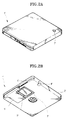
- mini-disks There are two types of mini-disks currently on the market, a recordable type mini-disk 1 shown in Figures 1A and 1B and a reproduction-only type mini-disk 1' shown in Figures 2A and 2B.
- Recordable mini-disk 1 has a cartridge shell 2 on both sides of which openings 3 and 4 are formed and a shutter 5 which shifts along a sliding groove 6forthe simultaneous opening or closing of openings 3 and 4.
- a disk 9 in cartridge shell 2 is exposed through openings 3 and 4 on two opposite sides of the cartridge shell.
- reproduction-only mini-disk 1' has a cartridge cell 2' on one side of which an opening 3' is formed and a shutter 5' which shifts along a sliding groove 6' for the opening of opening 3'.
- a sliding groove 6' for the opening of opening 3'.
- arrow marks 7 and 7' molded into the upper surfaces of cartridge cells 2 and 2'of mini-disks 1 and 1', respectively, indicate the direction in which the mini-disk is to be inserted into a player.
- cartridge shells 2 and 2' have recognition grooves 8 and 8' of different depths, by which the inserted mini-disk can be identified as being a recordable-type mini-disk or a reproduction-only type mini-disk.
- Sony's portable recording and/or reproducing player (model MZ-1) for mini-disks is currently on the market.
- This player comprises a slot for receiving the mini-disk in a slot-in method, a spindle motor for rotating the received mini-disk, an optical pickup for irradiating a focused light beam on one side of the disk, and a magnetic head for applying a magnetic field over the other side of the disk.
- the cartridge shell of the mini-disk which is received in the slot is loaded on a deck, with the shutter thereof slid open so as to open the opening. Simultaneously, the disk in the cartridge shell seats on a turn-table rotated by a spindle motor.
- the magnetic head During the rotation of the disk, if a reproduction mode is selected, the magnetic head remains lifted to an "up" position and the optical pickup alone operates. Here, if a recording mode is selected, the magnetic head is lowered to a "down" position by the motor so as to move together with the optical pickup which nearly contacts the opposite side of the disk. It should be noted thatwhile the reproduction-only mini-disk is loaded, the magnetic head cannot be lowered even if the recording mode is selected.
- Preferred embodiments of the present invention aim to provide a magneto-optical recording and/or reproducing apparatus which is light-weight and small and consumes little power, so as to be suitable for portability.
- a magneto-optical recording and/or reproducing apparatus for recording and/or reproducing information, using a disk cartridge which receives a magneto-optical disk in a rotatable state and having a deck on which the disk cartridge is loaded, an optical pickup assembly movably seated on the deck to project a focused light beam onto one surface of the magneto-optical disk, and a magnetic head for applying a magnetic field onto the other surface of the magneto-optical disk, said apparatus comprising:
- a magnetic head driving apparatus for a magneto-optical disk player using a disk cartridge which receives a magneto-optical disk, and having an optical pickup assembly moving with range of the radius of the magneto-optical disk to project a focused light beam onto one surface of the magneto-optical disk, and a magnetic head for applying a magnetic field onto the other surface of the magneto-optical disk.
- said apparatus comprising:
- said connecting member comprises a pickup connecting portion connected to the optical pickup assembly, a head connecting portion connected to the head. and a hinge for connecting the pickup connecting portion and the head connecting portion.
- An apparatus as above may further comprise a spring member for elastically biasing the head connecting portion in one rotating direction.
- the angle of the head connecting portion is adjustable with respect to the pickup connecting portion so as to adjust the horizontal position of the magnetic head.
- said magnetic head lifting means comprises:
- An apparatus as above may further comprise slide member locking means for locking the moving state of the slide member and releasing the locking state, by being interlocked with the motion of extracting the disk cartridge.
- said slide member locking means comprises a slide locking member moving perpendicularly to the moving direction of the slide member.
- a magneto-optical recording and/or reproducing apparatus as claimed in any of the preceding claims, further comprising extracting means for extracting the disk cartridge received in the cartridge holding member when the cartridge holding member moves from a loaded position to an unloaded position.
- a disk cartridge inserting and extracting apparatus for inserting and extracting a disk cartridge in which a magneto-optical disk is rotatably received, in a magneto-optical disk drive having a turntable on which the magneto-optical disk is seated and a deck on which an optical pickup assembly for projecting a focused light beam onto one surface of the magneto-optical disk is seated, said apparatus comprising:
- said extracting means comprises:
- said extracting member has a contact portion for contact with a disk cartridge inserted into the cartridge holding member, is arranged to move by the contact portion in the inserting direction of the disk cartridge, and is elastically biased to return the moved disk cartridge.
- said locking member is pivotally mounted to be rotatable and to be elastically biased in one direction. having a locking pin interlocked with the extracting member and a releasing pin interlocked with the locking releasing member.
- said locking releasing member is movable and has a one-direction elastic member which operates the locking member when moved in one direction and does not operate the locking member when moved in the opposite direction.
- the cartridge holding member which is simplified and rotatably opens/closes is used so as to load the disk cartridge to the deck. Since the cartridge holding member only has enough receiving space for the disk cartridge loaded on the deck to be seated, the cartridge holding member occupies less space than that of a conventional slot-in configuration. Also, the power consumption is reduced since the member can be manually operated. Further, since the magnetic head is raised/lowered by mechanically engaging with the disk cartridge inserted into the holding member, the space occupied by the motor for raising and lowering the magnetic head is reduced while reducing power consumption. Accordingly, such magneto-optical recording and/or reproducing apparatus can be further minimized, consume less power, and is suitable for portability.
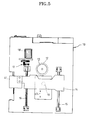
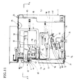
- reference numeral 10 denotes a deck while 20 denotes a cartridge holding member.
- Deck 10 has an upper surface 11 on which a mini-disk 1 of Figure 1 or mini-disk l'of Figure 2 may be loaded.
- a turn-table 12 for receiving the magneto-optical mini-disk is installed on upper surface 11.
- Turn-table 12 connects with a spindle motor 13 established beneath deck 10.
- An optical pickup assembly 14 is installed below deck 10, with the optical pickup assembly supported by a guide bar 15 and screw axis 16 which are parallel to each other so as to be moved in a direction a3 by the rotation of screw axis 16.
- Screw axis 16 connects with a transporting motor 18 via a gear group 17.
- Optical pickup assembly 14 includes an objective lens 19, and irradiates the light beam focussed by objective lens 19 onto the surface of the magneto-optical disk seated on turn- table 12 of deck 10.
- Optical pickup assembly 14 receives the reflected light beam from the magneto-optical disk, and thereby detects an electrical signal, i.e. a reproducing signal.
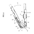
- cartridge holding member 20 receives mini-disk 1 of Figure 1 or mini-disk 1' of Figure 2 which is inserted in a direction al, with the cartridge holding member hinge-combined with deck 10 so as to be rotated in a direction a2 as shown in Figure 4 to meet the upper surface of deck 10.
- Cartridge holding member 20 has on one sidewall thereof a shutter opener 22 for opening a shutter 5 or 5' ( Figure 1 or Figure 2) when mini-disk is inserted and a shutter closure 23 for returning the shutter when the mini-disk is pulled back.
- a magnetic head 30 is installed above cartridge holding member 20. Magnetic head 30 is attached to one end of a flexible plane spring 31 which is supported by a head supporting member 32.
- a connecting member 40 for combining optical pickup assembly 14 and head supporting member 32 comprises a pickup connection portion 41 fixed on optical pickup assembly 14, a head connection portion 42 connected to head supporting member 32, and a hinge portion 43 for combining pickup connection portion 41 and head connection portion 42. Hinge portion 43 and hinge 21 connecting deck 10 with cartridge holding member 20 are on the same axis. Therefore.
- optical pickup assembly 14 and magnetic head 30 can be transported in the a3 direction of Figure 5 by means of connection member 40, and magnetic head 30 can rotate in the a2 direction, which is the same as that of the opening and closing movement of cartridge holding member 20, together with head supporting member 32 and head connection portion 42.
- magnetic head 30 is elastically biased downward by means of a torsion spring 44 which extends to head connection portion 42 and is fitted over hinge portion 43 as a sleeve.
- Head connection portion 42 of connection member40 has a protrusion 45 which protrudes downwardly, for connection with magnetic head lifting means described later.
- controlling screw 46 is screw- coupled with pickup connection portion 41 by boring thereinto, while one end of the controlling screw contacts an end portion of head connection portion 42. The controlling screw is for controlling the horizontal status of head supporting member 32.
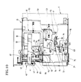
- cartridge holding member 20 has on the upper surface thereof extracting means for ejecting forward the received mini-disk, while the extracting means comprises an extracting member 50, a locking member 60 and a locking releasing member 70.
- Extracting member 50 is supported to be capable of being transported forward or backward by means of a groove 51 and a supporting pin 52, and is elastically biased by spring 53 in a forward direction. Extracting member 50 comprises a contact portion 54 contacting the front of a received mini-disk, a locking end 55 designed to be caught by locking pin 61 of locking member 60, and a head holder 56 extended beside ejection member 50 for holding up head supporting member 32 of magnetic head 30.
- Locking member 60 is supported by a pivot 62 to be capable of being rotated, while being elastically biased counterclockwise by a torsion spring 64, and has a locking releasing pin 63 on the opposing side thereof. Locking releasing pin 63 moves along with protrusion 72 of spring member 71 supported by locking releasing member 70, so that locking pin 61 retreats in the clockwise direction.
- Locking releasing member 70 is supported by groove 73 and supporting pin 74 to be capable of being translated forward or backward, and connects with deck 10 via link 75. Locking releasing member 70 is interlocked with the opening and closing movement of cartridge holding member 20, thereby to move forward or backward on cartridge holding member 20 with spring member 71.
- a slide member 80 is installed on the upper surface of cartridge holding member 20.
- Slide member 80 recognizes whether or not the received mini-disk is the recordable type. If a recordable mini-disk 1 ( Figure 1) is received, the slide member interlocks with mini-disk 1 to raise or lower magnetic head 30.
- Slide member 80 is supported by groove 81 and supporting pin 82 to move a short distance forward or backward, as shown in Figure 9, and is elastically biased forwardly by spring 83. Also, sliding member 80 has a protruded pin 85 on a bent portion 84 thereof.
- Protruded pin 85 is located to meet a recognition groove 8 or 8' ( Figure 1 or Figure 2) of mini-disk 1 or 1', so that the pin cannot be inserted into recognition groove 8 of a recordable mini-disk 1, but can be inserted into recognition groove 8' of reproduction-only mini-disk 1'.
- a head holding bar 86 is installed on slide member 80 and held in place by two fixing plates 87 and 88, and is about the same length as the radius of the magneto-optical disk.
- Slide member 80 has a supporting pin 91, and a locking member 90 having a groove is supported by supporting pin 91 to slightly move latitudinally.
- the locking member is elastically biased toward extracting member 50 by torsion spring 93.
- Slide locking member 90 includes a locking portion 95 which catches on the rear part of a locking pin 94 installed on cartridge holding member 20 and a locking releasing portion 96 triggered by a triggering pin 57 installed on extracting member 50 so as to retreat upwardly to unlock the engagement between locking portion 95 and locking pin 94.
- FIGS 10-14 illustrate the operation of the apparatus, using a recordable mini-disk 1.
- mini-disk 1 is injected into cartridge holding member 20 as shown in Figure 10. Therefore, the front part of mini-disk 1 just injected contacts a contact portion 54 of extracting portion 50.
- extracting portion 50 is slid in a direction a4, thereby to extend spring 53. Consequently, locking part 55 of extracting member 50 is caught and locked by a locking pin 61 of a locking member 60.
- Locking pin 55 one side of which is sloped, advances while pushing locking pin 61 downward, and then locking pin 61 returns back immediately, so that the locking function is completed as shown in Figure 11.
- a protruded pin 85 established in bending portion 84 of sliding member 80 does not enter recognition groove 8 of mini-disk 1, but contacts the forepart of mini-disk 1. Accordingly, slide member 80 is pushed back thereby to retract holding bar 86 which supports protruded portion 45 of head connection portion 42 of connection member 40. Next, magnetic head 30 is lowered to make contact with magneto-optical disk 9 of mini-disk 1.
- slide member 80 is pushed back a short distance from the initial position.
- Locking portion 95 of locking member 90 is locked by locking pin 94, as shown in Figure 11, so that a spring 83 for restoring slide member 80 prevents mini-disk 1 from coming back out via its insertion path.
- triggering pin 57 of extracting member 50 moves along the ejecting direction, while triggering locking releasing portion 96 of slide locking member 90. Therefore, slide locking member 90 is pushed upward so as for the locking portion 95 to be released from locking pin 94, whereby slide member 80 returns to its initial position. Accordingly, holding bar 86 also returns to its initial position, so that magnetic head 30 moves upward.
- Head holder 56 formed on head supporting member 32 of magnetic head 30 of extracting member 50 moves in the ejecting direction as shown in Figures 17 and 18, thereby moving head supporting member 32 upward. Therefore, damage to mini-disk 1 during its ejection is prevented because magnetic head 30 does not come into contact with the surface of the mini-disk.
- protruded pin 85 of slide member 80 is inserted into recognition groove 8' of mini-disk 1', so as not to push slide member 80 as shown in Figure 16.
- protrusion 45 of head connection portion 42 is supported by holding bar 86 coupled with slide member 80, which thereby prevents the downward movement of magnetic head 30.
- slide member 80 remains in an unpushed condition, so that slide locking member 90 supported by slide member 80 can stay in its original location ( Figure 10). All other operations are the same as those of the recordable mini-disk.
- the reproduction-only mini-disk without the shutter on the upper surface thereof avoids contact with the magnetic head. Therefore, recording and reproduction can be performed most optimally.
- FIG 19 shows another embodiment of an extracting means according to the present invention.
- a locking releasing member 70 is combined with a spring member 71'.
- Spring member 71' is shaped into multiple bends along an S-shaped path, whose middle portion 71 a is supported by a fixing pin 76, whose one end 71 b is permanently supported by a fixed protrusion 77 and whose other end 71c is supported by two guide supporting pins 78a and 78b, while fixing pin 76 and fixed protrusion 77 are installed on locking releasing member 70.
- End 71c of spring member 71' is elastically bent only by the movement of locking releasing member 70 in a direction a6, but is not bent by movement in the reverse direction. Therefore, locking releasing pin 63 of locking member 60 is struck so that locking member 60 rotates only during the opening of cartridge holding member 20. However, conversely, locking member 60 does not rotate in the case of closing cartridge holding member 20.
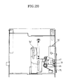
- Figure 20 shows another embodiment of an extracting means according to the present invention.
- the aforementioned spring member is excluded, and instead, an end portion 64 of locking member 60' is formed longer and a contacting member 79 is established on locking releasing member 70' so as to contact end portion 64.
- locking releasing member 70' moves in an a7 direction, and contacting member 79 pushes the end portion of locking member 60'.
- locking member 60' rotates for the unlocking of extracting member 50'.
- examples of the magneto-optical recording and reproducing apparatus have a simple structure by which a disk cartridge is loaded or unloaded with the insertion to a door-type cartridge holding member, and therefore the apparatus can be compacted to a portable size. Also, no power is required for the opening or closing of the cartridge holding member and forthe raising and lowering of the magnetic head, which therefore saves electrical power. Accordingly, examples of the present invention can provide a miniaturized magneto-optical recording and/or reproducing apparatus capable of being mounted on computer systems as well as being conveniently carried and used.
Applications Claiming Priority (8)
| Application Number | Priority Date | Filing Date | Title |
|---|---|---|---|
| KR1019920018175A KR0160617B1 (ko) | 1992-10-05 | 1992-10-05 | 카트리지 취출장치 |
| KR9218175 | 1992-10-05 | ||
| KR939795 | 1993-06-01 | ||
| KR939798 | 1993-06-01 | ||
| KR1019930009800A KR0138344B1 (ko) | 1993-06-01 | 1993-06-01 | 광자기 디스크 플레이어의 자기헤드 승강장치 |
| KR1019930009795A KR950001675A (ko) | 1993-06-01 | 1993-06-01 | 광자기 디스크 플레이어의 디스크 카트리지 삽입 및 취출장치 |
| KR939800 | 1993-06-01 | ||
| KR1019930009798A KR0138364B1 (ko) | 1993-06-01 | 1993-06-01 | 광자기 디스크 플레이어 |
Publications (3)
| Publication Number | Publication Date |
|---|---|
| EP0592192A2 true EP0592192A2 (de) | 1994-04-13 |
| EP0592192A3 EP0592192A3 (de) | 1995-07-26 |
| EP0592192B1 EP0592192B1 (de) | 1998-07-29 |
Family
ID=27482955
Family Applications (1)
| Application Number | Title | Priority Date | Filing Date |
|---|---|---|---|
| EP93307909A Expired - Lifetime EP0592192B1 (de) | 1992-10-05 | 1993-10-05 | Magnetooptisches Aufnehmen und Wiedergabe |
Country Status (4)
| Country | Link |
|---|---|
| US (2) | US5450377A (de) |
| EP (1) | EP0592192B1 (de) |
| JP (2) | JP3103467B2 (de) |
| DE (1) | DE69319986T2 (de) |
Cited By (7)
| Publication number | Priority date | Publication date | Assignee | Title |
|---|---|---|---|---|
| EP0630015A2 (de) * | 1993-06-01 | 1994-12-21 | Samsung Electronics Co., Ltd. | Vorrichtung zum Einzug/Auswurf eines Datenträgers in/aus eine(r) Wiedergabevorrichtung |
| EP0644540A1 (de) * | 1993-09-20 | 1995-03-22 | Sony Corporation | Aufzeichnungs-/Wiedergabegerät für eine Kassette, die ein Aufzeichnungsmedium enthält und Auswurfmechanismus davon |
| DE4443380A1 (de) * | 1993-12-06 | 1995-06-08 | Samsung Electronics Co Ltd | Kartuschen-Einführungs/Herausnahme-Vorrichtung für Abspielgeräte mit einer magnetooptischen Disk |
| EP0657879A2 (de) * | 1993-12-06 | 1995-06-14 | Samsung Electronics Co., Ltd. | Magnetooptischer Plattenspieler |
| EP0992991A2 (de) * | 1998-10-08 | 2000-04-12 | Sanyo Electric Co., Ltd. | Aufnahme- oder Wiedergabegerät für Platte in einer Kassette |
| CN1080427C (zh) * | 1994-06-21 | 2002-03-06 | 索尼公司 | 光拾取器 |
| EP1552523A1 (de) * | 2002-07-25 | 2005-07-13 | Samsung Electronics Co., Ltd. | Datenträgerkassette und datenträgerlaufwerkvorrichtung damit |
Families Citing this family (14)
| Publication number | Priority date | Publication date | Assignee | Title |
|---|---|---|---|---|
| MY123588A (en) * | 1993-08-26 | 2006-05-31 | Sony Corp | Recording and / or reproducing apparatus for recording medium and damper mechanism employed in such apparatus. |
| JPH07262639A (ja) * | 1994-03-18 | 1995-10-13 | Pioneer Electron Corp | 光磁気記録再生装置 |
| MY115952A (en) * | 1994-04-25 | 2003-10-31 | Sony Corp | Cd/cd-rom apparatus |
| WO1997019450A1 (fr) * | 1995-11-17 | 1997-05-29 | Sony Corporation | Appareil a tete magnetique et appareil d'enregistrement et/ou de reproduction sur support du type disque |
| US5666343A (en) * | 1995-12-29 | 1997-09-09 | Samsung Electronics Co., Ltd. | Disk player having a shutter opening structure in which a shutter of the disk cartridge is opened without a cartridge holder |
| US5805553A (en) * | 1996-05-13 | 1998-09-08 | Sony Corporation | Holder device and holder mounting method in holder device |
| JP3394138B2 (ja) * | 1996-09-27 | 2003-04-07 | アルプス電気株式会社 | 記録媒体の駆動装置 |
| JPH10208359A (ja) * | 1997-01-24 | 1998-08-07 | Sony Corp | 電子機器 |
| JP3425336B2 (ja) * | 1997-09-29 | 2003-07-14 | 松下電器産業株式会社 | ディスク装置 |
| JP3425337B2 (ja) | 1997-10-03 | 2003-07-14 | 松下電器産業株式会社 | ディスク装置 |
| KR100504565B1 (ko) * | 1998-06-03 | 2005-10-24 | 엘지전자 주식회사 | 디스크 구동장치 |
| US6526018B1 (en) * | 1999-12-08 | 2003-02-25 | Matsushita Electric Industrial Co., Ltd. | Disk cartridge |
| EP1482484A3 (de) * | 2003-05-28 | 2008-05-28 | Matsushita Electric Industrial Co., Ltd. | Magnetisches Kopfhebe- und Senk-Gerät |
| US7574715B2 (en) * | 2005-07-20 | 2009-08-11 | Apple Inc. | Disk drive media access system |
Citations (7)
| Publication number | Priority date | Publication date | Assignee | Title |
|---|---|---|---|---|
| EP0437091A2 (de) * | 1990-01-09 | 1991-07-17 | Sony Corporation | Plattenspieler |
| EP0439286A2 (de) * | 1990-01-20 | 1991-07-31 | Sony Corporation | Aufzeichnungsgerät für magnetooptische Platte |
| EP0455158A2 (de) * | 1990-04-28 | 1991-11-06 | Sony Corporation | Aufnahme- und Wiedergabegerät für magnetooptische Scheibe |
| JPH0485702A (ja) * | 1990-07-30 | 1992-03-18 | Toshiba Corp | 光磁気ディスク装置 |
| EP0475595A2 (de) * | 1990-08-24 | 1992-03-18 | Sony Corporation | Aufzeichnungs- und/oder Wiedergabegerät für optische Platten |
| EP0501337A2 (de) * | 1991-02-23 | 1992-09-02 | Sony Corporation | Scheibeaufzeichnung- und/oder -wiedergabegerät |
| EP0555815A1 (de) * | 1992-02-10 | 1993-08-18 | Sony Corporation | Plattenaufzeichnungsgerät |
Family Cites Families (4)
| Publication number | Priority date | Publication date | Assignee | Title |
|---|---|---|---|---|
| DE69011759T2 (de) * | 1989-06-15 | 1995-03-16 | Matsushita Electric Ind Co Ltd | Magneto-optisches Aufnahme- und/oder Wiedergabegerät. |
| JP2910114B2 (ja) * | 1990-01-20 | 1999-06-23 | ソニー株式会社 | 電子機器 |
| US5247496A (en) * | 1990-04-28 | 1993-09-21 | Sony Corporation | Recording and/or reproducing apparatus for using magneto-optical disc |
| JP3104884B2 (ja) * | 1991-11-05 | 2000-10-30 | キヤノン株式会社 | 光磁気ディスク装置 |
-
1993
- 1993-10-05 DE DE69319986T patent/DE69319986T2/de not_active Expired - Lifetime
- 1993-10-05 EP EP93307909A patent/EP0592192B1/de not_active Expired - Lifetime
- 1993-10-05 US US08/131,540 patent/US5450377A/en not_active Expired - Lifetime
- 1993-10-05 JP JP05249367A patent/JP3103467B2/ja not_active Expired - Lifetime
-
1995
- 1995-06-06 US US08/470,041 patent/US5590098A/en not_active Expired - Lifetime
-
1999
- 1999-08-16 JP JP22994399A patent/JP3523120B2/ja not_active Expired - Lifetime
Patent Citations (7)
| Publication number | Priority date | Publication date | Assignee | Title |
|---|---|---|---|---|
| EP0437091A2 (de) * | 1990-01-09 | 1991-07-17 | Sony Corporation | Plattenspieler |
| EP0439286A2 (de) * | 1990-01-20 | 1991-07-31 | Sony Corporation | Aufzeichnungsgerät für magnetooptische Platte |
| EP0455158A2 (de) * | 1990-04-28 | 1991-11-06 | Sony Corporation | Aufnahme- und Wiedergabegerät für magnetooptische Scheibe |
| JPH0485702A (ja) * | 1990-07-30 | 1992-03-18 | Toshiba Corp | 光磁気ディスク装置 |
| EP0475595A2 (de) * | 1990-08-24 | 1992-03-18 | Sony Corporation | Aufzeichnungs- und/oder Wiedergabegerät für optische Platten |
| EP0501337A2 (de) * | 1991-02-23 | 1992-09-02 | Sony Corporation | Scheibeaufzeichnung- und/oder -wiedergabegerät |
| EP0555815A1 (de) * | 1992-02-10 | 1993-08-18 | Sony Corporation | Plattenaufzeichnungsgerät |
Non-Patent Citations (1)
| Title |
|---|
| PATENT ABSTRACTS OF JAPAN vol. 16, no. 308 (P-1381) 7 July 1992 & JP-A-04 085 702 (TOSHIBA CORP.) 18 March 1992 * |
Cited By (16)
| Publication number | Priority date | Publication date | Assignee | Title |
|---|---|---|---|---|
| EP0630015A3 (de) * | 1993-06-01 | 1995-02-15 | Samsung Electronics Co Ltd | Vorrichtung zum Einzug/Auswurf eines Datenträgers in/aus eine(r) Wiedergabevorrichtung. |
| EP0630015A2 (de) * | 1993-06-01 | 1994-12-21 | Samsung Electronics Co., Ltd. | Vorrichtung zum Einzug/Auswurf eines Datenträgers in/aus eine(r) Wiedergabevorrichtung |
| US5659530A (en) * | 1993-09-20 | 1997-08-19 | Sony Corporation | Recording and/or reproducing apparatus for a cartridge accomodating a recording medium and an eject mechanism thereof |
| EP0644540A1 (de) * | 1993-09-20 | 1995-03-22 | Sony Corporation | Aufzeichnungs-/Wiedergabegerät für eine Kassette, die ein Aufzeichnungsmedium enthält und Auswurfmechanismus davon |
| US5831958A (en) * | 1993-09-20 | 1998-11-03 | Sony Corporation | Recording and/or reproducing apparatus for a cartridge accommodating a recording medium and an eject mechanism thereof |
| GB2284923B (en) * | 1993-12-06 | 1997-12-17 | Samsung Electronics Co Ltd | Cartridge inserting/extracting apparatus for a magnetooptical disk player |
| EP0657879A3 (de) * | 1993-12-06 | 1995-10-25 | Samsung Electronics Co Ltd | Magnetooptischer Plattenspieler. |
| GB2284923A (en) * | 1993-12-06 | 1995-06-21 | Samsung Electronics Co Ltd | A disk cartridge loading mechanism with locking means to prevent extraction of the cartridge |
| EP0657879A2 (de) * | 1993-12-06 | 1995-06-14 | Samsung Electronics Co., Ltd. | Magnetooptischer Plattenspieler |
| DE4443380A1 (de) * | 1993-12-06 | 1995-06-08 | Samsung Electronics Co Ltd | Kartuschen-Einführungs/Herausnahme-Vorrichtung für Abspielgeräte mit einer magnetooptischen Disk |
| DE4443380B4 (de) * | 1993-12-06 | 2004-06-24 | Samsung Electronics Co., Ltd., Suwon | Kassetten-Einführungs/Herausnahme-Vorrichtung für Abspielgeräte mit einer magnetooptischen Disk |
| CN1080427C (zh) * | 1994-06-21 | 2002-03-06 | 索尼公司 | 光拾取器 |
| EP0992991A2 (de) * | 1998-10-08 | 2000-04-12 | Sanyo Electric Co., Ltd. | Aufnahme- oder Wiedergabegerät für Platte in einer Kassette |
| EP0992991A3 (de) * | 1998-10-08 | 2000-12-06 | Sanyo Electric Co., Ltd. | Aufnahme- oder Wiedergabegerät für Platte in einer Kassette |
| EP1552523A1 (de) * | 2002-07-25 | 2005-07-13 | Samsung Electronics Co., Ltd. | Datenträgerkassette und datenträgerlaufwerkvorrichtung damit |
| EP1552523A4 (de) * | 2002-07-25 | 2007-02-28 | Samsung Electronics Co Ltd | Datenträgerkassette und datenträgerlaufwerkvorrichtung damit |
Also Published As
| Publication number | Publication date |
|---|---|
| DE69319986D1 (de) | 1998-09-03 |
| JP2000076725A (ja) | 2000-03-14 |
| JP3103467B2 (ja) | 2000-10-30 |
| JPH06267124A (ja) | 1994-09-22 |
| EP0592192A3 (de) | 1995-07-26 |
| US5450377A (en) | 1995-09-12 |
| DE69319986T2 (de) | 1999-03-04 |
| EP0592192B1 (de) | 1998-07-29 |
| US5590098A (en) | 1996-12-31 |
| JP3523120B2 (ja) | 2004-04-26 |
Similar Documents
| Publication | Publication Date | Title |
|---|---|---|
| EP0592192B1 (de) | Magnetooptisches Aufnehmen und Wiedergabe | |
| US6411584B2 (en) | Cartridge loading apparatus and methods of manufacturing and operating same | |
| AU711951B2 (en) | Cartridge loading apparatus and method | |
| KR0132857B1 (ko) | 광자기 디스크 플레이어의 자기헤드 승강장치 | |
| EP0855705B1 (de) | Lademechanismus für Speichermedien sowie Aufnahme- und/oder Wiedergabegerät mit einem solchen Mechanismus | |
| US5485329A (en) | Device for inserting/extracting a disk cartridge with locking mechanism | |
| US5610890A (en) | Cartridge inserting/extracting apparatus for a magnetooptical disk player | |
| KR100491575B1 (ko) | 디스크 카트리지 로딩장치 | |
| KR100189882B1 (ko) | 광자기 디스크 플레이어의 자기헤드 승강장치 | |
| KR0141215B1 (ko) | 광자기 디스크 플레이어의 카트리지 삽입인출장치 | |
| WO2001069599A1 (fr) | Memoire de masse a cartouches et dispositif d'enregistrement ou de reproduction sur disque | |
| KR0141216B1 (ko) | 광자기 디스크 플레이어의 카트리지 삽입인출장치 | |
| US8015575B2 (en) | Disk device with insertion slot capable of preventing double loading of disks | |
| KR0138364B1 (ko) | 광자기 디스크 플레이어 | |
| KR0138344B1 (ko) | 광자기 디스크 플레이어의 자기헤드 승강장치 | |
| KR950015201B1 (ko) | 미니디스크 플레이어의 디스크카트리지 삽입, 배출장치 | |
| JP2000123456A (ja) | ディスクドライブ装置 | |
| JP3806570B2 (ja) | カートリッジの収納装置 | |
| JP3754264B2 (ja) | カートリッジの収納装置 | |
| JP3439071B2 (ja) | カートリッジに収納されたディスクの記録装置 | |
| JP2005209232A (ja) | カートリッジの収納装置 | |
| AU6449799A (en) | Cartridge loading apparatus |
Legal Events
| Date | Code | Title | Description |
|---|---|---|---|
| PUAI | Public reference made under article 153(3) epc to a published international application that has entered the european phase |
Free format text: ORIGINAL CODE: 0009012 |
|
| AK | Designated contracting states |
Kind code of ref document: A2 Designated state(s): DE FR GB |
|
| PUAL | Search report despatched |
Free format text: ORIGINAL CODE: 0009013 |
|
| AK | Designated contracting states |
Kind code of ref document: A3 Designated state(s): DE FR GB |
|
| 17P | Request for examination filed |
Effective date: 19960105 |
|
| 17Q | First examination report despatched |
Effective date: 19961126 |
|
| GRAG | Despatch of communication of intention to grant |
Free format text: ORIGINAL CODE: EPIDOS AGRA |
|
| GRAG | Despatch of communication of intention to grant |
Free format text: ORIGINAL CODE: EPIDOS AGRA |
|
| GRAH | Despatch of communication of intention to grant a patent |
Free format text: ORIGINAL CODE: EPIDOS IGRA |
|
| GRAH | Despatch of communication of intention to grant a patent |
Free format text: ORIGINAL CODE: EPIDOS IGRA |
|
| GRAA | (expected) grant |
Free format text: ORIGINAL CODE: 0009210 |
|
| AK | Designated contracting states |
Kind code of ref document: B1 Designated state(s): DE FR GB |
|
| REF | Corresponds to: |
Ref document number: 69319986 Country of ref document: DE Date of ref document: 19980903 |
|
| ET | Fr: translation filed | ||
| PLBE | No opposition filed within time limit |
Free format text: ORIGINAL CODE: 0009261 |
|
| STAA | Information on the status of an ep patent application or granted ep patent |
Free format text: STATUS: NO OPPOSITION FILED WITHIN TIME LIMIT |
|
| 26N | No opposition filed | ||
| REG | Reference to a national code |
Ref country code: GB Ref legal event code: IF02 |
|
| PGFP | Annual fee paid to national office [announced via postgrant information from national office to epo] |
Ref country code: GB Payment date: 20120920 Year of fee payment: 20 |
|
| PGFP | Annual fee paid to national office [announced via postgrant information from national office to epo] |
Ref country code: FR Payment date: 20120927 Year of fee payment: 20 |
|
| PGFP | Annual fee paid to national office [announced via postgrant information from national office to epo] |
Ref country code: DE Payment date: 20120920 Year of fee payment: 20 |
|
| REG | Reference to a national code |
Ref country code: DE Ref legal event code: R071 Ref document number: 69319986 Country of ref document: DE |
|
| REG | Reference to a national code |
Ref country code: GB Ref legal event code: PE20 Expiry date: 20131004 |
|
| PG25 | Lapsed in a contracting state [announced via postgrant information from national office to epo] |
Ref country code: DE Free format text: LAPSE BECAUSE OF EXPIRATION OF PROTECTION Effective date: 20131008 Ref country code: GB Free format text: LAPSE BECAUSE OF EXPIRATION OF PROTECTION Effective date: 20131004 |