EP0591744B1 - Regeleinrichtung für Brennkraftmaschinen - Google Patents
Regeleinrichtung für Brennkraftmaschinen Download PDFInfo
- Publication number
- EP0591744B1 EP0591744B1 EP93115123A EP93115123A EP0591744B1 EP 0591744 B1 EP0591744 B1 EP 0591744B1 EP 93115123 A EP93115123 A EP 93115123A EP 93115123 A EP93115123 A EP 93115123A EP 0591744 B1 EP0591744 B1 EP 0591744B1
- Authority
- EP
- European Patent Office
- Prior art keywords
- fuel
- engine
- amount
- ratio
- butane
- Prior art date
- Legal status (The legal status is an assumption and is not a legal conclusion. Google has not performed a legal analysis and makes no representation as to the accuracy of the status listed.)
- Expired - Lifetime
Links
Images


Classifications
-
- F—MECHANICAL ENGINEERING; LIGHTING; HEATING; WEAPONS; BLASTING
- F02—COMBUSTION ENGINES; HOT-GAS OR COMBUSTION-PRODUCT ENGINE PLANTS
- F02D—CONTROLLING COMBUSTION ENGINES
- F02D41/00—Electrical control of supply of combustible mixture or its constituents
- F02D41/0025—Controlling engines characterised by use of non-liquid fuels, pluralities of fuels, or non-fuel substances added to the combustible mixtures
- F02D41/0047—Controlling exhaust gas recirculation [EGR]
- F02D41/0065—Specific aspects of external EGR control
-
- F—MECHANICAL ENGINEERING; LIGHTING; HEATING; WEAPONS; BLASTING
- F02—COMBUSTION ENGINES; HOT-GAS OR COMBUSTION-PRODUCT ENGINE PLANTS
- F02D—CONTROLLING COMBUSTION ENGINES
- F02D37/00—Non-electrical conjoint control of two or more functions of engines, not otherwise provided for
- F02D37/02—Non-electrical conjoint control of two or more functions of engines, not otherwise provided for one of the functions being ignition
-
- F—MECHANICAL ENGINEERING; LIGHTING; HEATING; WEAPONS; BLASTING
- F02—COMBUSTION ENGINES; HOT-GAS OR COMBUSTION-PRODUCT ENGINE PLANTS
- F02D—CONTROLLING COMBUSTION ENGINES
- F02D41/00—Electrical control of supply of combustible mixture or its constituents
- F02D41/0025—Controlling engines characterised by use of non-liquid fuels, pluralities of fuels, or non-fuel substances added to the combustible mixtures
- F02D41/003—Adding fuel vapours, e.g. drawn from engine fuel reservoir
- F02D41/0042—Controlling the combustible mixture as a function of the canister purging, e.g. control of injected fuel to compensate for deviation of air fuel ratio when purging
-
- F—MECHANICAL ENGINEERING; LIGHTING; HEATING; WEAPONS; BLASTING
- F02—COMBUSTION ENGINES; HOT-GAS OR COMBUSTION-PRODUCT ENGINE PLANTS
- F02D—CONTROLLING COMBUSTION ENGINES
- F02D41/00—Electrical control of supply of combustible mixture or its constituents
- F02D41/0025—Controlling engines characterised by use of non-liquid fuels, pluralities of fuels, or non-fuel substances added to the combustible mixtures
- F02D41/003—Adding fuel vapours, e.g. drawn from engine fuel reservoir
- F02D41/0045—Estimating, calculating or determining the purging rate, amount, flow or concentration
-
- F—MECHANICAL ENGINEERING; LIGHTING; HEATING; WEAPONS; BLASTING
- F02—COMBUSTION ENGINES; HOT-GAS OR COMBUSTION-PRODUCT ENGINE PLANTS
- F02D—CONTROLLING COMBUSTION ENGINES
- F02D41/00—Electrical control of supply of combustible mixture or its constituents
- F02D41/0025—Controlling engines characterised by use of non-liquid fuels, pluralities of fuels, or non-fuel substances added to the combustible mixtures
- F02D41/0047—Controlling exhaust gas recirculation [EGR]
- F02D41/005—Controlling exhaust gas recirculation [EGR] according to engine operating conditions
-
- F—MECHANICAL ENGINEERING; LIGHTING; HEATING; WEAPONS; BLASTING
- F02—COMBUSTION ENGINES; HOT-GAS OR COMBUSTION-PRODUCT ENGINE PLANTS
- F02D—CONTROLLING COMBUSTION ENGINES
- F02D41/00—Electrical control of supply of combustible mixture or its constituents
- F02D41/02—Circuit arrangements for generating control signals
- F02D41/04—Introducing corrections for particular operating conditions
- F02D41/047—Taking into account fuel evaporation or wall wetting
-
- F—MECHANICAL ENGINEERING; LIGHTING; HEATING; WEAPONS; BLASTING
- F02—COMBUSTION ENGINES; HOT-GAS OR COMBUSTION-PRODUCT ENGINE PLANTS
- F02M—SUPPLYING COMBUSTION ENGINES IN GENERAL WITH COMBUSTIBLE MIXTURES OR CONSTITUENTS THEREOF
- F02M25/00—Engine-pertinent apparatus for adding non-fuel substances or small quantities of secondary fuel to combustion-air, main fuel or fuel-air mixture
- F02M25/08—Engine-pertinent apparatus for adding non-fuel substances or small quantities of secondary fuel to combustion-air, main fuel or fuel-air mixture adding fuel vapours drawn from engine fuel reservoir
-
- F—MECHANICAL ENGINEERING; LIGHTING; HEATING; WEAPONS; BLASTING
- F02—COMBUSTION ENGINES; HOT-GAS OR COMBUSTION-PRODUCT ENGINE PLANTS
- F02P—IGNITION, OTHER THAN COMPRESSION IGNITION, FOR INTERNAL-COMBUSTION ENGINES; TESTING OF IGNITION TIMING IN COMPRESSION-IGNITION ENGINES
- F02P5/00—Advancing or retarding ignition; Control therefor
- F02P5/04—Advancing or retarding ignition; Control therefor automatically, as a function of the working conditions of the engine or vehicle or of the atmospheric conditions
- F02P5/045—Advancing or retarding ignition; Control therefor automatically, as a function of the working conditions of the engine or vehicle or of the atmospheric conditions combined with electronic control of other engine functions, e.g. fuel injection
-
- F—MECHANICAL ENGINEERING; LIGHTING; HEATING; WEAPONS; BLASTING
- F02—COMBUSTION ENGINES; HOT-GAS OR COMBUSTION-PRODUCT ENGINE PLANTS
- F02B—INTERNAL-COMBUSTION PISTON ENGINES; COMBUSTION ENGINES IN GENERAL
- F02B2275/00—Other engines, components or details, not provided for in other groups of this subclass
- F02B2275/18—DOHC [Double overhead camshaft]
-
- F—MECHANICAL ENGINEERING; LIGHTING; HEATING; WEAPONS; BLASTING
- F02—COMBUSTION ENGINES; HOT-GAS OR COMBUSTION-PRODUCT ENGINE PLANTS
- F02D—CONTROLLING COMBUSTION ENGINES
- F02D41/00—Electrical control of supply of combustible mixture or its constituents
- F02D41/0025—Controlling engines characterised by use of non-liquid fuels, pluralities of fuels, or non-fuel substances added to the combustible mixtures
- F02D41/0047—Controlling exhaust gas recirculation [EGR]
-
- Y—GENERAL TAGGING OF NEW TECHNOLOGICAL DEVELOPMENTS; GENERAL TAGGING OF CROSS-SECTIONAL TECHNOLOGIES SPANNING OVER SEVERAL SECTIONS OF THE IPC; TECHNICAL SUBJECTS COVERED BY FORMER USPC CROSS-REFERENCE ART COLLECTIONS [XRACs] AND DIGESTS
- Y02—TECHNOLOGIES OR APPLICATIONS FOR MITIGATION OR ADAPTATION AGAINST CLIMATE CHANGE
- Y02T—CLIMATE CHANGE MITIGATION TECHNOLOGIES RELATED TO TRANSPORTATION
- Y02T10/00—Road transport of goods or passengers
- Y02T10/10—Internal combustion engine [ICE] based vehicles
- Y02T10/40—Engine management systems
Definitions
- a control system for an internal combustion engine having an intake passage, a fuel tank, at least one fuel injection valve, at least one combustion chamber, and an evaporative emission control system
- the evaporative emission control system including a canister for adsorbing evaporative fuel generated from the fuel tank, a purging passage connecting between the intake passage and the canister, and a purge control valve for controlling a flow rate of a gas containing the evaporative fuel and purged from the canister into the intake passage.
- an amount of fuel to be injected by the injection valve and the ratio of the amount of fuel to be injected to the amount of fuel to be purged from the canister are calculated based on operating conditions of the engine, and based on this ratio, the purge control valve is controlled and at the same time the amount of fuel to be injected is decreased.
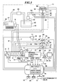
- the atmospheric pressure chamber 34 is communicated to the atmosphere via an air inlet port 34a, while the negative pressure chamber 35 is connected to one end of a negative pressure-introducing passage 36.
- the negative pressure-introducing passage 36 has the other end thereof connected to the intake pipe 2 at a location between the purging passage 9 and the other end of the exhaust gas recirculation passage 25, for introducing the absolute pressure PBA (negative pressure) into the negative pressure chamber 35.
- the negative pressure-introducing passage 36 has an air-introducing passage 37 connected to an intermediate portion thereof, and the air-introducing passage 37 has a pressure control valve 38 arranged in an intermediate portion thereof.
- the pressure control valve 38 is an electromagnetic valve of a normally-closed type, and negative pressure prevailing within the negative pressure-introducing passage 38 is controlled by the pressure control valve 38, whereby a predetermined level of negative pressure is created within the negative pressure chamber 35.
- the leaning correction coefficient KLS is set to "1" when the engine is not in a leaning region in which the air-fuel ratio of a mixture supplied to the engine should be controlled to a lean value, whereas when the engine is in the leaning region, it is set to a predetermined value smaller than "1", which is dependent on the leaning region.
- the valve lift command value LPUCMD is determined by executing the LPUCMD-determining routine (see Fig. 26) mentioned at the step S8 of the Fig. 5 main routine. If none of the three conditions is satisfied, i.e.
- a QBE map is retrieved to determine a first basic flow rate value QBEM.
- the QBE map is set, e.g. as shown in Fig. 10, such that map values QBEM (00, 00) to QBEM (15, 15) are provided in a manner corresponding to predetermined values PBG00 to PBG15 of negative pressure (gauge pressure) within the intake pipe 2 as a difference between the atmospheric pressure PA and the intake pipe absolute pressure PBA, and predetermined values LPACT00 to LPACT15 of the net valve lift value LPACT of the PRG L sensor 52.
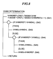
- the injection fuel decremental coefficient KPUN is calculated.
- the injection fuel decremental coefficient decreases the amount of fuel (gasoline) to be injected by the fuel injection valve 6, in view of the fact that butane as evaporative fuel is purged into the intake pipe 2 from the canister 43.
- a basic injected fuel decremental coefficient KPUM is determined by retrieving a KPU map.
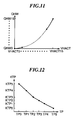
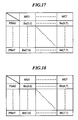
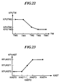
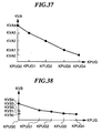
- the KPUAST table is set, e.g. as shown in Fig. 23, such that table values KPUAST0 to KPUAST2 are provided in a manner corresponding to predetermined values KAST0 to KAST4 of an after-start enriching coefficient KAST.
- the after-start enriching coefficient KAST increases an amount of fuel supplied to the engine immediately after the start of the engine, which is set to a smaller value as time elapses after the start of the engine, and when the engine is in a normal operating condition, it is set to "1.0".
- the after-start correction coefficient KPUAST is set to a larger value.
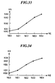
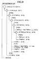
- the KVB table is set, e.g. as shown in Fig. 38, such that table values KVB0 to KVB4 are provided in a manner corresponding to predetermined values KPUG0 to KPUG4 of the injected fuel ratio KPUG.
- the butane correction coefficient KVB is determined by retrieving the KVB table and additionally by interpolation, if required.
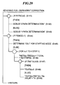
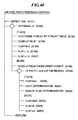
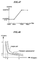
- Fig. 39 shows a TWP-determining routine for determining the amount TWP of adhering fuel, which is executed for each cylinder whenever the crankshaft rotates through a predetermined angle (e.g. 30 degrees).
- step S176 it is determined at a step S176, whether or not the adhering amount TWP(k) of fuel is equal to or smaller than a predetermined very small value TWPLG. If TWP(k) ⁇ TWPLG, it is judged that the adhering amount TWP(k) is negligible or zero, so that the adhering amount TWP(k) is set to "0" and the flag FTWPR is set to "1" at a step S178. Then, at a step S179, the flag FCTWP is set to "1" to indicate completion of the calculation of the adhering amount TWP of fuel, followed by terminating the program.
- the first term on the right side represents an amount of fuel which has not been carried off from the adhering fuel and remains on the inner wall surface of the intake pipe during the present cycle
- the second term on the right side represents an amount of fuel corresponding to a portion of injected fuel which has not been drawn into the combustion chamber and newly adhered to the inner wall surface of the intake pipe 2.
- the program proceeds to a step S203, where the flag FLAFFB is set to "0" and the air-fuel ratio correction coefficient KLAF and the I-term thereof KLAFI are both set to "1.0" at steps S204 and S205, respectively, followed by terminating the program.
- the gain coefficients KP, KI, KD and the thinning-out variable NI are determined by retrieving an Aeg-Me map.
- the flag FIDL is not equal to "0"
- gain coefficients KPI, KII and KDI, and the thinning-out variable NII suitable for idling are read out from the memory means, and set to the gain coefficients KP, KI, KD and the thinning-out variable NI, followed by the program returning to the Fig. 41 main routine.
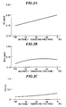
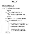
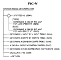
- the optimum ignition timing varies with the ratio of the amount of evaporative fuel to the total amount of fuel supplied to the engine, in other words, with the injection fuel ratio KPUG. Therefore, in the present embodiment, the ignition timing control is performed in a manner responsive to the injection fuel ratio KPUG.
- the correction coefficients ⁇ IGPUT, KIGRTW, KIGRPB, and ⁇ IGCR are commonly used for the low speed V/T and the high speed V/T, this is not limitative, but they may be separately determined depending on the selected one of the low speed V/T and the high speed V/T, if required.
Landscapes
- Engineering & Computer Science (AREA)
- Chemical & Material Sciences (AREA)
- Combustion & Propulsion (AREA)
- Mechanical Engineering (AREA)
- General Engineering & Computer Science (AREA)
- Electrical Control Of Air Or Fuel Supplied To Internal-Combustion Engine (AREA)
- Supplying Secondary Fuel Or The Like To Fuel, Air Or Fuel-Air Mixtures (AREA)
Claims (2)
- Regelsystem einer Brennkraftmaschine (1) mit einer Einlaßpassage (2), einem Kraftstofftank (41), wenigstens einem Kraftstoffeinspritzventil (6), wenigstens einer Brennkammer und einem Dampfemissionsregelsystem (10), wobei das Dampfemissionsregelsystem (10) einen Behälter (43) zur Adsorption von in dem Kraftstofftank (41) erzeugtem Kraftstoffdampf, eine Spülpassage (9), die zwischen der Einlaßpassage und dem Behälter (43) angeschlossen ist, und ein Spülsteuerventil (47) zur Steuerung einer Flußrate von Gas, das den Kraftstoffdampf enthält und aus dem Behälter (43) in die Einlaßpassage (2) gespült wird, umfaßt,
wobei das Regelsystem umfaßt:- ein Betriebszustand-Erfassungsmittel (12, 15, 16) zum Erfassen von Betriebszuständen der Maschine einschließlich wenigstens der Drehzahl der Maschine und der Belastung der Maschine;- ein Kraftstoffeinspritzmengenberechnungsmittel (S93) zur Berechnung einer durch das Kraftstoffeinspritzventil einzuspritzenden Kraftstoffmenge auf Basis von Ergebnissen der Erfassung durch das Maschinenbetriebszustand-Erfassungsmittel (12, 15, 16);- ein Verhältnisberechnungsmittel (S7) zur Berechnung eines Verhältnisses der von dem Kraftstoffeinspritzventil (6) einzuspritzenden Kraftstoffmenge zu einer aus dem Behälter (43) in die Einlaßpassage (2) zu spülenden Kraftstoffmenge auf Basis von Ergebnissen der Erfassung durch das Maschinenbetriebszustand-Erfassungsmittel (12, 14, 15, 16, 23);- ein Spülsteuermittel (10) zur Betriebssteuerung des Spülsteuerventils (47) auf Basis von Ergebnissen der Berechnung durch das Verhältnisberechnungsmittel (S7); und- ein Kraftstoffeinspritzmengenminderungsmittel (S94, S95, S96) zur Minderung der von dem Kraftstoffeinspritzventil einzuspritzenden Kraftstoffmenge auf Basis von Ergebnissen der Berechnung durch das Verhältnisberechnungsmittel (S7);
wobei das Verhältnisberechnungsmittel (S7) ein Grenzsetzmittel (S107) umfaßt, um eine Grenze des Verhältnisses entsprechend einer Untergrenze einer Kraftstoffmenge zu setzen, die von dem Kraftstoffeinspritzventil (6) eingespritzt werden kann, während eine lineare Beziehung zwischen einer Zeitperiode, während der das Kraftstoffeinspritzventil (6) geöffnet ist, und der von dem Einspritzventil (6) einzuspritzenden Kraftstoffmenge gehalten wird. - Regelsystem nach Anspruch 1, in dem die Maschine eine Auslaßpassage (21) und einen in der Auslaßpassage (21) angeordneten katalytischen Wandler (22) aufweist, wobei- das Betriebszustandserfassungsmittel wenigstens ein Aufwärmzustanderfassungsmittel (14) zum Erfassen eines Aufwärmzustands der Maschine, sowie ein Aktivzustanderfassungsmittel (23) zum Erfassen eines aktivierten Zustands des katalytischen Wandlers (22) umfaßt, und wobei- das Verhältnisberechnungsmittel (S7) ein Bestimmungsmittel (S105) umfaßt, um das Verhältnis der von dem Kraftstoffeinspritzventil (6) einzuspritzenden Kraftstoffmenge zu der aus dem Behälter (43) in die Einlaßpassage (2) zu spülenden Kraftstoffmenge, wenigstens auf Basis von Ergebnissen der Erfassung durch das Aufwärmzustanderfassungsmittel (14) und Ergebnissen der Erfassung durch das Aktivzustanderfassungsmittel (23), zu bestimmen.
Priority Applications (1)
| Application Number | Priority Date | Filing Date | Title |
|---|---|---|---|
| EP95105046A EP0675278B1 (de) | 1992-09-18 | 1993-09-20 | Regeleinrichtung für Brennkraftmaschinen |
Applications Claiming Priority (8)
| Application Number | Priority Date | Filing Date | Title |
|---|---|---|---|
| JP275402/92 | 1992-09-18 | ||
| JP04275403A JP3135706B2 (ja) | 1992-09-18 | 1992-09-18 | 内燃エンジンの制御装置 |
| JP275404/92 | 1992-09-18 | ||
| JP27540192A JPH06101542A (ja) | 1992-09-18 | 1992-09-18 | 内燃エンジンの制御装置 |
| JP275403/92 | 1992-09-18 | ||
| JP27540492A JPH06101530A (ja) | 1992-09-18 | 1992-09-18 | 内燃エンジンの制御装置 |
| JP275401/92 | 1992-09-18 | ||
| JP27540292A JPH06101522A (ja) | 1992-09-18 | 1992-09-18 | 内燃エンジンの制御装置 |
Related Child Applications (2)
| Application Number | Title | Priority Date | Filing Date |
|---|---|---|---|
| EP95105046A Division EP0675278B1 (de) | 1992-09-18 | 1993-09-20 | Regeleinrichtung für Brennkraftmaschinen |
| EP95105046.7 Division-Into | 1995-04-04 |
Publications (2)
| Publication Number | Publication Date |
|---|---|
| EP0591744A1 EP0591744A1 (de) | 1994-04-13 |
| EP0591744B1 true EP0591744B1 (de) | 1995-12-20 |
Family
ID=27479048
Family Applications (2)
| Application Number | Title | Priority Date | Filing Date |
|---|---|---|---|
| EP95105046A Expired - Lifetime EP0675278B1 (de) | 1992-09-18 | 1993-09-20 | Regeleinrichtung für Brennkraftmaschinen |
| EP93115123A Expired - Lifetime EP0591744B1 (de) | 1992-09-18 | 1993-09-20 | Regeleinrichtung für Brennkraftmaschinen |
Family Applications Before (1)
| Application Number | Title | Priority Date | Filing Date |
|---|---|---|---|
| EP95105046A Expired - Lifetime EP0675278B1 (de) | 1992-09-18 | 1993-09-20 | Regeleinrichtung für Brennkraftmaschinen |
Country Status (3)
| Country | Link |
|---|---|
| US (2) | US5426938A (de) |
| EP (2) | EP0675278B1 (de) |
| DE (2) | DE69301079T2 (de) |
Cited By (1)
| Publication number | Priority date | Publication date | Assignee | Title |
|---|---|---|---|---|
| US6305360B1 (en) | 1996-07-10 | 2001-10-23 | Oribital Engine Company (Australia) Pty Limited | Fuel purge control |
Families Citing this family (27)
| Publication number | Priority date | Publication date | Assignee | Title |
|---|---|---|---|---|
| GB2309744B (en) * | 1993-07-06 | 1998-03-04 | Ford Motor Co | Controlling ignition timing in an internal combustion engine |
| JPH07208249A (ja) * | 1994-01-12 | 1995-08-08 | Honda Motor Co Ltd | 内燃エンジンの制御装置 |
| US5758308A (en) * | 1994-12-30 | 1998-05-26 | Honda Giken Kogyo Kabushiki Kaisha | Fuel metering control system for internal combustion engine |
| JP3438386B2 (ja) * | 1995-03-16 | 2003-08-18 | 日産自動車株式会社 | エンジンの燃料蒸気処理装置 |
| JP3286492B2 (ja) * | 1995-04-28 | 2002-05-27 | 本田技研工業株式会社 | 車載発電装置の制御装置 |
| JPH09195864A (ja) * | 1996-01-17 | 1997-07-29 | Nippon Soken Inc | 内燃機関の蒸発燃料処理装置 |
| JPH09202131A (ja) * | 1996-01-24 | 1997-08-05 | Fuji Heavy Ind Ltd | フューエル臭の車室内侵入防止装置 |
| JPH09242621A (ja) * | 1996-03-07 | 1997-09-16 | Honda Motor Co Ltd | 内燃機関の蒸発燃料制御装置 |
| JP3651133B2 (ja) * | 1996-08-27 | 2005-05-25 | 株式会社デンソー | 内燃機関の空燃比制御装置 |
| DE19726559A1 (de) * | 1997-06-23 | 1998-12-24 | Bosch Gmbh Robert | Diagnosemodul |
| JP3264221B2 (ja) * | 1997-07-28 | 2002-03-11 | 株式会社デンソー | 内燃機関の空燃比制御装置 |
| JP3361252B2 (ja) * | 1997-08-14 | 2003-01-07 | 本田技研工業株式会社 | 内燃機関の排気ガス浄化装置 |
| US6561166B2 (en) | 2000-06-13 | 2003-05-13 | Visteon Global Technologies, Inc. | Purge fuel canister measurement method and system |
| US6443138B1 (en) * | 2000-07-31 | 2002-09-03 | Daimlerchrysler Corporation | Full range fuel shift determination |
| DE10039952C2 (de) * | 2000-08-16 | 2003-04-24 | Siemens Ag | Verfahren zur Überprüfung einer Abgasrückführanlage |
| DE10141929A1 (de) * | 2001-08-28 | 2003-03-27 | Volkswagen Ag | Verfahren zum Starten eines Ottomotors |
| DE10310109B4 (de) * | 2003-03-06 | 2009-08-20 | Carl Freudenberg Kg | Anordnung zum dosierten Einspeisen von flüchtigen Kraftstoffbestandteilen, insbesondere in das Ansaugrohr einer Verbrennungskraftmaschine eines Kraftfahrzeugs |
| US6868837B2 (en) * | 2003-03-07 | 2005-03-22 | General Motors Corporation | Cold start fuel vapor enrichment |
| US8464518B2 (en) * | 2003-12-18 | 2013-06-18 | GM Global Technology Operations LLC | Fuel vapor enrichment for exhaust exothermic catalyst light-off |
| JP4376723B2 (ja) * | 2004-07-30 | 2009-12-02 | トヨタ自動車株式会社 | 内燃機関の点火時期制御方法 |
| JP4260079B2 (ja) * | 2004-08-06 | 2009-04-30 | 株式会社日本自動車部品総合研究所 | 内燃機関の燃料性状計測装置および内燃機関 |
| ATE419457T1 (de) * | 2007-02-08 | 2009-01-15 | Delphi Tech Inc | Kraftstoffdampf-tankentlüftungssystem für einen fahrzeugkraftstofftank |
| US8666635B2 (en) * | 2010-12-27 | 2014-03-04 | Toyota Jidosha Kabushiki Kaisha | Control device for internal combustion engine |
| FR2989119A1 (fr) * | 2012-04-05 | 2013-10-11 | Peugeot Citroen Automobiles Sa | Procede de commande d'une alimentation en carburant d'un moteur a combustion interne equipant un vehicule automobile |
| JP6669124B2 (ja) * | 2017-04-21 | 2020-03-18 | トヨタ自動車株式会社 | 内燃機関 |
| KR102692479B1 (ko) * | 2018-12-17 | 2024-08-07 | 현대자동차주식회사 | 가변 밸브 듀레이션 기구 및 액티브 퍼지 시스템을 구비한 차량의 공연비 제어 방법 |
| JP2021060025A (ja) * | 2019-10-09 | 2021-04-15 | トヨタ自動車株式会社 | 車両およびその制御方法 |
Family Cites Families (11)
| Publication number | Priority date | Publication date | Assignee | Title |
|---|---|---|---|---|
| JPS5999055A (ja) * | 1982-11-26 | 1984-06-07 | Nippon Soken Inc | 燃料制御装置 |
| US4512317A (en) * | 1984-02-27 | 1985-04-23 | Allied Corporation | Extended range throttle body fuel injection system |
| US4677956A (en) * | 1985-07-19 | 1987-07-07 | Ford Motor Company | Solenoid duty cycle modulation for dynamic control of refueling vapor purge transient flow |
| JPH01136667U (de) * | 1988-03-14 | 1989-09-19 | ||
| US4886026A (en) * | 1988-09-01 | 1989-12-12 | Ford Motor Company | Fuel injection control system |
| JP2909548B2 (ja) * | 1989-03-20 | 1999-06-23 | トヨタ自動車株式会社 | 内燃機関 |
| JP2793273B2 (ja) * | 1989-07-26 | 1998-09-03 | 松下電工株式会社 | コーナ水切り部の構造 |
| US5060621A (en) * | 1989-08-28 | 1991-10-29 | Ford Motor Company | Vapor purge control system |
| US5143040A (en) * | 1990-08-08 | 1992-09-01 | Toyota Jidosha Kabushiki Kaisha | Evaporative fuel control apparatus of internal combustion engine |
| CA2077068C (en) * | 1991-10-03 | 1997-03-25 | Ken Ogawa | Control system for internal combustion engines |
| US5363832A (en) * | 1992-05-14 | 1994-11-15 | Nippondenso Co., Ltd. | Fuel vapor purging control system with air/fuel ratio compensating system for internal combustion engine |
-
1993
- 1993-09-17 US US08/122,190 patent/US5426938A/en not_active Expired - Fee Related
- 1993-09-20 DE DE69301079T patent/DE69301079T2/de not_active Expired - Fee Related
- 1993-09-20 EP EP95105046A patent/EP0675278B1/de not_active Expired - Lifetime
- 1993-09-20 DE DE69316393T patent/DE69316393T2/de not_active Expired - Fee Related
- 1993-09-20 EP EP93115123A patent/EP0591744B1/de not_active Expired - Lifetime
-
1995
- 1995-02-15 US US08/388,836 patent/US5483935A/en not_active Expired - Fee Related
Cited By (1)
| Publication number | Priority date | Publication date | Assignee | Title |
|---|---|---|---|---|
| US6305360B1 (en) | 1996-07-10 | 2001-10-23 | Oribital Engine Company (Australia) Pty Limited | Fuel purge control |
Also Published As
| Publication number | Publication date |
|---|---|
| US5426938A (en) | 1995-06-27 |
| EP0591744A1 (de) | 1994-04-13 |
| EP0675278A2 (de) | 1995-10-04 |
| US5483935A (en) | 1996-01-16 |
| DE69316393T2 (de) | 1998-04-30 |
| DE69316393D1 (de) | 1998-02-19 |
| DE69301079D1 (de) | 1996-02-01 |
| EP0675278A3 (de) | 1995-10-25 |
| EP0675278B1 (de) | 1998-01-14 |
| DE69301079T2 (de) | 1996-06-13 |
Similar Documents
| Publication | Publication Date | Title |
|---|---|---|
| EP0591744B1 (de) | Regeleinrichtung für Brennkraftmaschinen | |
| US5724808A (en) | Air-fuel ratio control system for internal combustion engines | |
| US5611320A (en) | Control system for internal combustion engines | |
| US5655363A (en) | Air-fuel ratio control system for internal combustion engines | |
| US5699778A (en) | Fuel evaporative emission suppressing apparatus | |
| CA2072707C (en) | Air-fuel ratio control system for variable valve timing type internal combustion engines | |
| US5220904A (en) | Air-fuel ratio control system for internal combustion engines | |
| CA2136908C (en) | Fuel injection amount control system for internal combustion engines and intake passage wall temperature-estimating device used therein | |
| US5343846A (en) | Control system for internal combustion engines | |
| US5690074A (en) | Fuel injection control system for internal combustion engines | |
| US5630397A (en) | Control system for internal combustion engines | |
| US4915081A (en) | Method of determining activation of exhaust gas ingredient-concentration sensors for internal combustion engines | |
| US5241943A (en) | Air-fuel ratio control method for internal combustion engines | |
| US5572978A (en) | Fuel injection control system for internal combustion engines | |
| JPH06101522A (ja) | 内燃エンジンの制御装置 | |
| US5209213A (en) | Air-fuel ratio control method for internal combustion engines | |
| US5329909A (en) | Evaporative fuel-purging control system for internal combustion engines | |
| US5186155A (en) | Air-fuel ratio control method for internal combustion engines | |
| US5682866A (en) | Air-fuel ratio control system for internal combustion engines | |
| US5144932A (en) | Air-fuel ratio control method for internal combustion engines | |
| US5778865A (en) | Evaporative fuel control system for internal combustion engines | |
| US11970989B2 (en) | Method and system for improving evaporative emissions of a vehicle | |
| US5165381A (en) | Air-fuel ratio control method for internal combustion engines | |
| JP3135706B2 (ja) | 内燃エンジンの制御装置 | |
| JPH06101542A (ja) | 内燃エンジンの制御装置 |
Legal Events
| Date | Code | Title | Description |
|---|---|---|---|
| PUAI | Public reference made under article 153(3) epc to a published international application that has entered the european phase |
Free format text: ORIGINAL CODE: 0009012 |
|
| AK | Designated contracting states |
Kind code of ref document: A1 Designated state(s): DE FR GB |
|
| 17P | Request for examination filed |
Effective date: 19940420 |
|
| 17Q | First examination report despatched |
Effective date: 19940908 |
|
| GRAA | (expected) grant |
Free format text: ORIGINAL CODE: 0009210 |
|
| AK | Designated contracting states |
Kind code of ref document: B1 Designated state(s): DE FR GB |
|
| XX | Miscellaneous (additional remarks) |
Free format text: TEILANMELDUNG 95105046.7 EINGEREICHT AM 20/09/93. |
|
| REF | Corresponds to: |
Ref document number: 69301079 Country of ref document: DE Date of ref document: 19960201 |
|
| ET | Fr: translation filed | ||
| PLBE | No opposition filed within time limit |
Free format text: ORIGINAL CODE: 0009261 |
|
| 26N | No opposition filed | ||
| PGFP | Annual fee paid to national office [announced via postgrant information from national office to epo] |
Ref country code: FR Payment date: 20000912 Year of fee payment: 8 |
|
| REG | Reference to a national code |
Ref country code: GB Ref legal event code: IF02 |
|
| PG25 | Lapsed in a contracting state [announced via postgrant information from national office to epo] |
Ref country code: FR Free format text: LAPSE BECAUSE OF NON-PAYMENT OF DUE FEES Effective date: 20020531 |
|
| REG | Reference to a national code |
Ref country code: FR Ref legal event code: ST |
|
| PGFP | Annual fee paid to national office [announced via postgrant information from national office to epo] |
Ref country code: GB Payment date: 20030917 Year of fee payment: 11 |
|
| PGFP | Annual fee paid to national office [announced via postgrant information from national office to epo] |
Ref country code: DE Payment date: 20031002 Year of fee payment: 11 |
|
| PG25 | Lapsed in a contracting state [announced via postgrant information from national office to epo] |
Ref country code: GB Free format text: LAPSE BECAUSE OF NON-PAYMENT OF DUE FEES Effective date: 20040920 |
|
| PG25 | Lapsed in a contracting state [announced via postgrant information from national office to epo] |
Ref country code: DE Free format text: LAPSE BECAUSE OF NON-PAYMENT OF DUE FEES Effective date: 20050401 |
|
| GBPC | Gb: european patent ceased through non-payment of renewal fee |
Effective date: 20040920 |