EP0590349B1 - Magnetometersonde - Google Patents
Magnetometersonde Download PDFInfo
- Publication number
- EP0590349B1 EP0590349B1 EP93114161A EP93114161A EP0590349B1 EP 0590349 B1 EP0590349 B1 EP 0590349B1 EP 93114161 A EP93114161 A EP 93114161A EP 93114161 A EP93114161 A EP 93114161A EP 0590349 B1 EP0590349 B1 EP 0590349B1
- Authority
- EP
- European Patent Office
- Prior art keywords
- inductor
- probe
- magnetometer
- axis
- casing
- Prior art date
- Legal status (The legal status is an assumption and is not a legal conclusion. Google has not performed a legal analysis and makes no representation as to the accuracy of the status listed.)
- Expired - Lifetime
Links
Images

Classifications
-
- G—PHYSICS
- G01—MEASURING; TESTING
- G01V—GEOPHYSICS; GRAVITATIONAL MEASUREMENTS; DETECTING MASSES OR OBJECTS; TAGS
- G01V13/00—Manufacturing, calibrating, cleaning, or repairing instruments or devices covered by groups G01V1/00 – G01V11/00
-
- G—PHYSICS
- G01—MEASURING; TESTING
- G01R—MEASURING ELECTRIC VARIABLES; MEASURING MAGNETIC VARIABLES
- G01R33/00—Arrangements or instruments for measuring magnetic variables
- G01R33/02—Measuring direction or magnitude of magnetic fields or magnetic flux
- G01R33/022—Measuring gradient
-
- G—PHYSICS
- G01—MEASURING; TESTING
- G01V—GEOPHYSICS; GRAVITATIONAL MEASUREMENTS; DETECTING MASSES OR OBJECTS; TAGS
- G01V3/00—Electric or magnetic prospecting or detecting; Measuring magnetic field characteristics of the earth, e.g. declination, deviation
- G01V3/08—Electric or magnetic prospecting or detecting; Measuring magnetic field characteristics of the earth, e.g. declination, deviation operating with magnetic or electric fields produced or modified by objects or geological structures or by detecting devices
- G01V3/10—Electric or magnetic prospecting or detecting; Measuring magnetic field characteristics of the earth, e.g. declination, deviation operating with magnetic or electric fields produced or modified by objects or geological structures or by detecting devices using induction coils
- G01V3/104—Electric or magnetic prospecting or detecting; Measuring magnetic field characteristics of the earth, e.g. declination, deviation operating with magnetic or electric fields produced or modified by objects or geological structures or by detecting devices using induction coils using several coupled or uncoupled coils
Definitions
- the invention relates to a magnetometer probe with an arrangement from a tubular probe housing in which each other spaced and substantially coaxial with the probe housing two magnetic inductors are arranged by which a first inductor about a transverse to the axis of the probe housing located pivot axis is pivotally mounted.
- magnetometer probes are known either to find and locate iron parts in the ground or also used for geophysical magnetic field measurements will.
- saturation magnetometers in the manner of a Field strength difference meter enforced.
- Basis of a such a magnetometer probe form two magnetically sensitive Inductors that are coaxial and with a predetermined base distance arranged in a search tube of about 500 to 600 mm in length are.
- Both inductors of such a search arrangement are in Difference switched so that the earth's magnetic field is largely compensated.
- One near the magnetometer located ferromagnetic part causes Disturbance of the magnetic earth field or the own field of the ferromagnetic part overlaps the earth's field.
- Approximation of the magnetometer probe to the ferromagnetic Part as well as by the spatial distance between the inductors creates an electric one according to amount and direction Differential signal that is displayed optically and acoustically.
- Such magnetometer probes are very sensitive; she solve about a hundred thousandth of the total intensity of the earth's field and are therefore able to produce differential field strengths in the nanotesla area and therefore also deep-seated ferromagnetic parts, such as hidden ones Bombs to prove. Essential requirements to achieve such sensitivity are the so-called parallelization and the electrical adjustment of the Inductors.
- the mechanical parallelization of the two Inductors require an accuracy of about 1/100 degrees, so that the inductors occupy the same position in the room so that those exerted by the earth's magnetic field Induction on the respective inductor by the same
- the opposite amount is the same.
- both are inductors in the tubular probe housing by means of one on one Articulated connection provided at the end of the respective inductor pivoted and point to the other Open an externally adjustable worm gear, which can be operated to carry out the parallelization.
- an externally adjustable worm gear which can be operated to carry out the parallelization.
- Magnetometer probes In the generic type adjustable by means of two worm drives Magnetometer probes is parallelization very difficult, if not impossible, for unfamiliar people feasible, especially if the inductors are strongly misaligned and are not reference points for a pre-comparison are given, because an alternate adjustment of the first and the second inductor must necessarily be up to one Point to be carried out in which the desired parallelism the position in the room with sufficient accuracy sets.
- magnetometer probes are particularly useful ball-like joints and with screw-like fine threads mechanically very complex and therefore very expensive.
- all parts are measured mechanically and into one Probe insert can be selected.
- a magnetometer probe is known in which the two inductors each with an adjustment device are provided, the pivoting of the two Inductors relative to the magnetometer housing around each other right-angled transverse axes of the magnetometer housing allow.
- the adjustment devices point a complex structure and are therefore also expensive in the production.
- US-3,961,245 discloses a magnetometer probe with a movable core made of magnetizable Material described. As part of the alignment of the arrangement the entire housing with the inductor structure around an axis rotated perpendicular to the direction of the earth's magnetic field. This will result in a possible adjustment error of the inductors remaining signal determined.
- the Inductors are firmly connected to the housing.
- the GB 2 078 968 A relates to a probe arrangement with two longitudinally in a probe housing arranged inductors.
- a core made of easily magnetizable material which in a cap is arranged at one end of the housing, be moved perpendicular to the longitudinal direction of the housing.
- a compensation is done by moving and rotating the ring on the Housing reached.
- the compensation devices based on the effect of one placed near one of the inductors Based on easily magnetizable material, has the disadvantage that the magnetization of these substances is temperature-dependent to a non-negligible extent. Thus, misalignment often occurs when used off-road due to temperature changes.
- the compensation arrangements, at least on the pivotability one of the inductors are based, not very high Accuracy. To the required accuracy of compensation must achieve a delicacy in the adjustment of the swivel angle be enabled, even with extremely elaborate Adjustment devices is not easily achieved.
- the object of the present invention is to design a generic magnetometer probe in such a way that it is easy and inexpensive to manufacture and can be easily pre-calibrated already in manufacture and permits easy adjustment to be carried out. Another object is to provide a method for calibrating such a magnetometer probe.
- the first task is according to the Claim 1 solved.
- two types of adjustment which are interlinked, can be distinguished in the magnetometer probe arrangement. This is parallelization on the one hand and “swing adjustment” on the other. In the parallelization, the spatial position of the two inductors is aligned so that the voltages induced by the earth's field in the inductors are opposite in the same way. The complete swing adjustment is then usually carried out by electrical balancing of the two inductor windings.
- the impedance of the two inductor windings can be symmetrized from the outside in such a way that an almost complete swing adjustment - with good parallelization - is possible even without electrical adjustment.
- the design of the metal, tubular probe housing with two opposite, longitudinal slots has the effect that, on the one hand, the eddy current losses and the temperature coefficient values decrease. On the other hand, this also means that the short-circuit rings can be used again to intervene more in the electrical adjustment.
- the embodiment according to claim 3 allows a simple Swiveling the first inductor, since this inductor for Panning can be moved at its free end.
- the embodiment according to claim 4 not only allows one easy manufacture of the magnetometer probe, but also a reliable rotatability of the inductors and protects the inductors against mechanical external influences.
- the configuration is also advantageous for production according to claim 14, wherein the plastic insert from a or several plastic bushing (s) can exist on the their inside as a bearing for a rotatable inductor serves or serve.
- a major advantage of designing a plastic insert for holding the inductor holder in a metal tube is also that the eddy current effects are reduced will. This can reduce the eddy current effects be achieved that a larger outer metal pipe with thinner wall thickness is used. Beyond that through the plastic insert and especially its large Surface reached a sliding fit for the inductor holder.
- a construction is particularly expedient in which two or more O-rings are provided in the outer surface of the inductor holder, distributed over its longitudinal extent, for example in grooves, which allow the inductor holder to be guided centrally.
- the O-rings allow the inductor holder to be guided completely free of play and centrally.
- the fit between the inductor holder and the probe housing or a socket provided between them can also be tolerated somewhat larger, since the O-rings can completely absorb the play that may arise.
- the O-rings relax this backlash-free seat so that a high mechanical long-term consistency is created in the parallelization.
- metal short-circuit rings according to claim 15 or claim 16 creates a controllable mutual inductance, which has a particularly strong effect on a probe housing developed from plastic, but also with a probe housing shows effect from a non-magnetic metal.
- By moving these shorting rings is an outer one Fine adjustment of the magnetometer probe possible.
- the at the Execution of the metal probe housing according to claim 13 through the eddy currents induced by the probe winding mutual inductance arising in the metal probe housing causes the outer short-circuit rings at this Execution only a relatively small possibility of influence create.
- a magnetometer probe according to claim 17 with a metal tubular probe housing which in the Area of the inductors at least two in the longitudinal direction of the Probe housing has extending slots is already reliably adjustable on its own and has a high temporal stability of an adjustment.
- the Longitudinal slots interrupt the eddy current flow in the metal probe housing, creating the mutual inductance and the dampening effect can be reduced.
- the change associated with a change in temperature of the electrical resistance of the tubular probe housing is compensated by the provision of the slots, in particular an adjustment of this compensation is possible by longitudinal displacement of the short-circuit rings.
- the method specified in claim 22 for matching a Magnetometer probe according to the invention can already after Manufacture of the magnetometer probe, before delivery, for For the purpose of a rough pre-comparison, where the simplicity of the process a problem-free integration in the manufacturing process.
- the trainings of this Process according to claims 23 and 24 already create during the manufacture or the first adjustment of the magnetometer probe a reliable basis for later fine Readjustments, for which usually only the last step of claim 22 must be carried out. Provides an additional advantageous adjustment option the method step of claim 25.
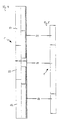
- Fig. 1 is a probe arrangement of a magnetometer probe or a magnetometer according to the invention in part sectioned view.
- the probe assembly has a tubular probe housing 1 into which one Plastic sleeve 11 is inserted.
- Probe housing 1 in the area of its free open ends each also provided with an inserted plastic bushing be.
- the plastic insert 11 (sleeve or socket) has on each of the two open ends of the probe housing 1 a hole on, which runs coaxially to the tubular probe housing 1 and serves to receive an inductor holder 22, 32, the Outer circumference on the inner circumference of the plastic insert 11 is adapted in the area of the assigned hole.
- Any inductor holder 22, 32 has a section at one end enlarged diameter 221, 321, the formation of a radial annular end face 222, 322 in the Sections 223, 323 with the inside diameter of the plastic insert 11 adapted smaller diameter passes.
- the region 223, 323 of smaller diameter is on its Outer circumference with at least two spaced apart Provide circumferential grooves in the O-rings 224, 224 ', 224' ', 324, 324 ', 324' 'are used.
- the O-rings take care of it their internal stress or due to their internal stress resulting surface pressure for an absorbent, play-free Seat in the plastic insert 11 and thus in the probe tube 1.
- the inductor holder 22, 32 By adding a suitable long-term grease, such as e.g. Silicone paste, when inserting the inductor holder 22, 32, the inductor holder 22, 32 becomes free of play and thus also coaxially arranged in the inductor holders respective inductors 2, 3 around the axis 10 of the probe housing 1 guaranteed.
- a suitable long-term grease such as e.g. Silicone paste
- the inductor 2, 3, which is preferably one made of a magnetic strip existing magnet sensitive with primary and secondary winding Element is centered in the inductor holder and thus coaxial to the axis 10 of the probe housing 1 arranged.
- the second inductor holder 32 (upper in FIG. 1) takes the assigned inductor 3 so that it assumes a coaxial fixed position, but around its own Axis, and thus about the axis 10 of the probe housing, rotatable is.
- the first (lower in FIG. 1) is inductor holder 22 formed as a hollow body, the inductor 2 pivotable records.
- the inductor 2 is at its second End 21 facing inductor 3 with a bronze wire 24 connected, which in turn is centered with the inductor holder 22 is connected so that there is one for the inductor 2 centric suspension results.
- End 28 of the pivotable inductor 2 is a central one Axle piece 29 axially out of the inductor 2.
- the free end this axle piece 29 engages in a right angle from the axis 10 of the probe housing 1 and the pivot axis 20 formed plane arranged longitudinal slot 40 of the first inductor holder 22 closing at its free end Cover part 4, so that the axle part 29 at Swiveling the inductor 2 moves along the longitudinal slot 40.
- the axle piece 29 is marked on its end face provided with a scale on the front of the cover part 4 as a display device 26 for the Swing angle of the inductor 2 acts (Fig. 3).
- Another The marking is larger on the outer circumference of section 221 Diameter of the first inductor holder 22 is provided (Fig. 2). This marking acts with one of these located adjacent Graduation on the outer circumference of the probe housing 1 together and forms a display device 27 for the Angle of rotation of the first inductor 2 about the axis 10 of the Probe housing.
- the probe housing 1 can be made of non-ferrous metal, preferably made of thin, high-strength aluminum, as well a high-strength composite plastic, such as glass fiber reinforced Plastic or carbon fiber reinforced plastic consist.
- the metal version is made of metal tubular probe housing 1 starting from the probe winding Eddy currents induced in the probe housing 1, the one cause strong mutual inductance. By a change the temperature becomes a change in electrical resistance causes the metal probe housing, so that a Temperature drift in the probe arrangement can occur which leads to instability of the measurements. For this The reason is the metal probe tube 1 in the area of the inductors 2, 3 provided with longitudinal slots 14, 14 ', 15, wherein each inductor has two radially opposite slots 14, 14 'are assigned.
- the two longitudinal slots 14, 14 'of the first inductor 2 are opposite by 90 ° around the axis 10 of the probe housing 1 the longitudinal slots 15 of the second inductor are rotated arranged.
- Each inductor can also do more than two longitudinal slots may be assigned.
- the longitudinal slots 14, 14 ', 15 the eddy current in the metal tubular probe housing 1 interrupted, so that the Eddy current caused mutual inductance can be influenced. Due to the slot length, the mutual inductance of the probe tube 1 be changed so that the temperature coefficient compensate at both inductor positions.
- the probe housing 1 is encompassing Metal short-circuit rings 12, 13 are provided arranged longitudinally displaceable with respect to the probe housing 1 are what the short-circuit rings have an internal thread can do that with an external thread of the probe housing 1 interacts. This can be moved on the outside of the probe housing 1 arranged arranged metal short-circuit rings a controllable mutual inductance, which in particular with a a special plastic housing shows strong impact. But also in the version with one slotted, metal probe housing can be in the area of the slots reduced mutual inductance by means of the Short-circuit rings can be increased locally for an adjustment to make.
- the well-known evaluation and display electronics of both inductors 2, 3 is in the middle area of the tube or rod-shaped probe housing.
- the ready-to-use probe assembly is attached to one iron-free location rotatable about the axis 10 of the probe housing 1 hung.
- a rough pre-adjustment is achieved that the first (lower) inductor 2 in its central position brought, in which the display device 26 a Displays the middle position.
- the probe is then rotated about its own axis 10 around the To determine the level of non-disclosure due to a lack of parallelization.
- the scale provided on the circumference of the probe tube is attached in such a way that the enlarged circumference 221 provided on the section Ad occupies a center marker.
- the determined Scale values of the display devices 26 and 27 are noted and form the basis for a reproducible Adjustment point in the technical data of the device is recorded. In this way the device service considerably simplified.
- the probe housing any other cross-sectional shape, for example have a rectangular shape, where appropriate also the inductors are arranged such that the Inductor axes parallel to each other and parallel to the axis of the probe housing are aligned or can be aligned.
- FIG. 4 shows another, very advantageous designed probe housing 1, the middle area has an aluminum tube 50, on both sides Plastic tube 51.52 is applied.
- the respective plastic tube 51, 52 in the end region of the aluminum tube 50 is used.
- Suitable for this e.g. a perfect fit with a permanent bond between aluminum tube 50 and plastic tube 51.
- the inside diameter The plastic tube 51, 52 can reach the end area stepped down again, with a slightly larger inner diameter be trained. This area can then the inductor holder can be provided with a sliding fit.
- the example according to FIG. 5 basically shows the same Structure as shown in Fig. 4. However, there is the middle part of the Probe housing 1 is longer than aluminum tube 50, so that shorter plastic tubes 51, 52 on both sides, e.g. from the length of the inductor holder with the aluminum tube 50 are connected.
- FIGS. 4 and 5 therefore show mechanically and constructively inexpensive probe housings, which are also electric, e.g. by avoiding Eddy currents in the inductor zone, excellent properties to have.
Landscapes
- Physics & Mathematics (AREA)
- Life Sciences & Earth Sciences (AREA)
- Engineering & Computer Science (AREA)
- General Physics & Mathematics (AREA)
- Geophysics (AREA)
- General Life Sciences & Earth Sciences (AREA)
- Remote Sensing (AREA)
- Environmental & Geological Engineering (AREA)
- Geology (AREA)
- Electromagnetism (AREA)
- Manufacturing & Machinery (AREA)
- Condensed Matter Physics & Semiconductors (AREA)
- Measuring Magnetic Variables (AREA)
- Investigating Or Analyzing Materials By The Use Of Magnetic Means (AREA)
- Video Image Reproduction Devices For Color Tv Systems (AREA)
Description
Dies ist einerseits die Parallelisierung und andererseits der "Schaukelabgleich".
Bei der Parallelisierung wird die räumlich Lage der beiden Induktoren so ausgerichtet, daß die vom Erdfeld in den Induktoren induzierten Spannungen entgegengesetzt gleich sind. Der vollständige Schaukelabgleich erfolgt dann üblicherweise durch elektrische Symmetrierung der beiden Induktorwicklungen.
Die Ausgestaltung des metallenen, rohrförmigen Sondengehäuses mit zwei gegenüberliegenden, längs verlaufenen Schlitzen, bewirkt, daß zum einen die Wirbelstromverluste und die Temperaturkoeffizientenwerte absinken. Zum anderen wird dadurch auch erreicht, daß mittels der Kurzschlußringe wieder stärker in den elektrischen Abgleich eingegriffen werden kann.
Die O-Ringe gestatten eine völlig spielfreie und zentrische Führung des Induktorhalters. Zum anderen jedoch kann aber auch dadurch die Passung zwischen Induktorhalter und dem Sondengehäuse bzw. einer dazwischen vorgesehen Buchse, etwas größer toleriert werden, da die O-Ringe das eventuell entstehende Spiel völlig aufnehmen können. Weiterhin entspannen die O-Ringe diesen spielfreien Sitz so, daß eine hohe mechanische Langzeitkonstanz in der Parallelisierung entsteht.
- Fig. 1
- eine teilweise geschnittene Seitenansicht einer Anordnung einer erfindungsgemäßen Magnetometersonde,
- Fig. 2
- eine ungeschnittene Seitenansicht einer weiteren Ausführung einer Sondenanordnung,
- Fig. 3
- eine Stirnansicht einer Magnetometersonde gemäß der Erfindung aus Richtung III,
- Fig. 4
- eine Ansicht und einen axialen Schnitt durch ein Sondengehäuse einer weiteren Ausführungsform, die allein im mittleren Bereich ein metallenes Rohr und beidseitig dazu ein aufgebrachtes Kunststoffrohr aufweist, und
- Fig. 5
- eine Ansicht eines Sondengehäuses mit ähnlichem Aufbau wie nach Fig. 4.
Claims (25)
- Magnetometersonde mit einem rohrförmigen Sondengehäuse (1), in dem voneinander beabstandet und im wesentlichen koaxial zum Sondengehäuse (1) zwei Induktoren (2, 3) angeordnet sind, wobei mindestens ein erster Induktor (2) um eine quer zur Achse (10) des Sondengehäuses (1) gelegene Achse (20) schwenkbar gelagert ist und beide Induktoren (2, 3) unabhängig voneinander um die Achse (10) des Sondengehäuses (1) drehbar gelagert sind.
- Magnetometersonde nach Anspruch 1,
dadurch gekennzeichnet,
daß beide Induktoren (2, 3) unabhängig voneinander um eine zur Achse (10) des Sondengehäuses (1) senkrechte Achse schwenkbar gelagert sind. - Magnetometersonde nach Anspruch 2,
dadurch gekennzeichnet,
daß die Schwenkachse (20) des ersten Induktors (2) im Bereich des dem zweiten Induktor (3) zugewandten Endes (21) oder diesem Ende (21) benachbart gelegen ist. - Magnetometersonde nach einem der vorhergehenden Ansprüche,
dadurch gekennzeichnet,
daß zumindest einer der um die Achse (10) des Sondengehäuses (1) drehbaren Induktoren (2, 3) in einem Induktorhalter (22, 32) angeordnet ist und
daß der Induktorhalter (22, 32) im Sondengehäuse (1) um dessen Achse (10) drehbar gelagert ist. - Magnetometersonde nach einem der vorhergehenden Ansprüche,
dadurch gekennzeichnet,
daß der dreh- und schwenkbare erste Induktor (2) innerhalb eines Induktorhalters (22) schwenkbar gelagert ist
und daß der Induktorhalter (22) im Sondengehäuse (1) um dessen Achse (10) drehbar gelagert ist. - Magnetometersonde nach Anspruch 5,
dadurch gekennzeichnet,
daß der schwenkbare Induktor (2) innerhalb des Induktorhalters (22) zentrisch an einem Bronzedraht (24) schwenkbar aufgehängt ist. - Magnetometersonde nach einem der vorhergehenden Ansprüche,
dadurch gekennzeichnet,
daß der schwenkbare Induktor (2) mit einer die Schwenkbewegung beaufschlagenden Justiervorrichtung (25) versehen ist. - Magnetometersonde nach Anspruch 7,
dadurch gekennzeichnet,
daß die Justiervorrichtung (25) mit einer den Grad der Verschwenkung wiedergebenden Anzeigeeinrichtung (26) zusammenwirkt. - Magnetometersonde nach einem der Ansprüche 7 oder 8,
dadurch gekennzeichnet,
daß die Justiervorrichtung (25) zwei entgegengesetzt wirkende, den Induktor arretierende Schrauben (25', 25'') aufweist. - Magnetometersonde nach einem der Ansprüche 7 oder 8,
dadurch gekennzeichnet,
daß die Justiervorrichtung (25) eine den Induktor (2) gegen die Kraft einer Feder arretierende Schraube aufweist. - Magnetometersonde nach einem der vorhergehenden Ansprüche,
dadurch gekennzeichnet,
daß zumindest ein drehbarer Induktor (2, 3) bzw. Induktorhalter (22, 32) mit einer den Grad der Verdrehung wiedergebenden Anzeigeeinrichtung (27) zusammenwirkt. - Magnetometersonde nach einem der vorhergehenden Ansprüche,
dadurch gekennzeichnet,
daß das Sondengehäuse (1) aus einem Kunststoffmaterial besteht. - Magnetometersonde nach einem der Ansprüche 1 bis 11,
dadurch gekennzeichnet,
daß das Sondengehäuse (1) aus einem nichtmagnetischen Metall, vorzugsweise aus Aluminium, besteht. - Magnetometersonde nach Anspruch 13,
dadurch gekennzeichnet,
daß das Sondengehäuse (1) auf seiner Innenseite einen Kunststoffeinsatz (11) aufweist, der den Induktorhalter (22, 32), insbesondere saugend, aufnimmt. - Magnetometersonde nach einem der vorhergehenden Ansprüche,
dadurch gekennzeichnet,
daß im Bereich der Induktoren (2, 3) das Sondengehäuse (1) umgreifende metallene Kurzschlußringe (12, 13) angeordnet sind, die bezüglich des Sondengehäuses (1) längsverschieblich angeordnet sind. - Magnetometersonde nach Anspruch 15,
dadurch gekennzeichnet,
daß die Kurzschlußringe (12, 13) ein Innengewinde aufweisen, das zur Längsverstellung mit einem Außengewinde des Sondengehäuses (1) zusammenwirkt. - Magnetometersonde nach einem der Ansprüche 13 bis 16,
dadurch gekennzeichnet,
daß das metallene rohrförmige Sondengehäuse im Bereich der Induktoren (2, 3) zumindest zwei in Längsrichtung des Sondengehäuses (1) verlaufende Schlitze aufweist. - Magnetometersonde nach einem der Ansprüche 1 bis 17,
dadurch gekennzeichnet,
daß der Induktorhalter (22, 32) mit einer spielfreien und zentrischen Führung (224, 324) im Sondengehäuse (1) oder einem Kunststoffeinsatz (11) des Sondengehäuses (1) angeordnet ist. - Magnetometersonde nach Anspruch 18,
dadurch gekennzeichnet,
daß über die Länge des Induktorhalters (22, 32) verteilt mindestens zwei O-Ringe (224, 324) zur spielfreien Führung im Sondengehäuse (1) vorhanden sind. - Magnetometersonde nach einem der Ansprüche 1 bis 12,
dadurch gekennzeichnet,
daß das rohrförmige Sondengehäuse (1) im axial mittleren Bereich als Aluminiumrohr (50) ausgebildet ist, mit dem beidseitig ein Kunststoffrohr (51, 52) verbunden ist. - Magnetometersonde nach Anspruch 20,
dadurch gekennzeichnet,
daß das jeweilige Kunststoffrohr (51, 52) als Gleitbüchse für einen Induktorhalter (21, 32) ausgeführt und paßgenau in das Aluminiumrohr (50) eingesetzt, insbesondere verklebt, ist. - Verfahren zum Abgleichen einer Magnetometersonde nach einem der Ansprüche 1 bis 21,
gekennzeichnet
durch die folgenden Schritte:die Sonde wird an einem eisenfreien Ort, mit der Achse (10) des Sondengehäuses (1) in vertikaler Richtung, positioniert, wobei der schwenkbare Induktor (2) eine unverschwenkte Mittelposition einnimmt,die Sonde wird im Bereich geringer Empfindlichkeit lichkeit um die Achse (10) gedreht,beide Induktoren (2,3) werden verdreht bis eine auftretende Fehlanzeige minimiert ist,der zweite Induktor (3) wird fixiert, und vorzugsweise wird seine Verdrehposition markiert,der erste Induktor (2) wird abwechselnd verdreht und/oder verschwenkt, bis auch die verbliebene Fehlanzeige minimiert ist. - Verfahren nach Anspruch 22,
dadurch gekennzeichnet,
daß in einem weiteren Schritt die dem ersten Induktor (2) zugeordneten Anzeigeeinrichtungen (26, 27) jeweils den Bezugswert "Null" erhalten. - Verfahren nach einem der Ansprüche 22 oder 23,
dadurch gekennzeichnet,
daß ausgehend von den im Abgleich erhaltenen Werten der Anzeigeeinrichtungen (26, 27) eine Kalibrierkurve der Magnetometersonde erstellt wird. - Verfahren nach einem der Ansprüche 22 bis 24,
dadurch gekennzeichnet,
daß ein elektrischer Schaukelabgleich durch axiales Verlagern der Kurzschlußringe (12, 13) erfolgt.
Applications Claiming Priority (2)
| Application Number | Priority Date | Filing Date | Title |
|---|---|---|---|
| DE4232466 | 1992-09-28 | ||
| DE4232466A DE4232466A1 (de) | 1992-09-28 | 1992-09-28 | Magnetometersonde |
Publications (3)
| Publication Number | Publication Date |
|---|---|
| EP0590349A2 EP0590349A2 (de) | 1994-04-06 |
| EP0590349A3 EP0590349A3 (de) | 1995-04-05 |
| EP0590349B1 true EP0590349B1 (de) | 1998-03-25 |
Family
ID=6469023
Family Applications (1)
| Application Number | Title | Priority Date | Filing Date |
|---|---|---|---|
| EP93114161A Expired - Lifetime EP0590349B1 (de) | 1992-09-28 | 1993-09-03 | Magnetometersonde |
Country Status (3)
| Country | Link |
|---|---|
| EP (1) | EP0590349B1 (de) |
| AT (1) | ATE164455T1 (de) |
| DE (2) | DE4232466A1 (de) |
Cited By (1)
| Publication number | Priority date | Publication date | Assignee | Title |
|---|---|---|---|---|
| DE102014113657A1 (de) * | 2014-09-22 | 2016-03-24 | Hermann Sewerin Gbr (Vertretungsberechtigter Gesellschafter: Dr. Rer. Nat. Swen Sewerin , 33330 Gütersloh) | Vorrichtung zur Ortung ferromagnetischer Objekte |
Families Citing this family (5)
| Publication number | Priority date | Publication date | Assignee | Title |
|---|---|---|---|---|
| DE29805631U1 (de) * | 1998-03-27 | 1998-06-25 | Ebinger, Klaus, 51149 Köln | Magnetometer |
| DE20118655U1 (de) * | 2001-11-15 | 2002-01-31 | Fa. Ing. Klaus Ebinger, 51149 Köln | Magnetometersonde |
| DE102004059199A1 (de) † | 2004-07-02 | 2006-02-09 | OKM Ortungstechnik Krauß & Müller GmbH | Anordnung zum Betreiben eines geophysikalischen Ortungsgeräts |
| EP2012143B1 (de) * | 2007-07-05 | 2014-11-12 | Vallon GmbH | Kompensationsverfahren für die Differenzspannungsabweichung bei unterschiedlicher Ausrichtung eines Sensorrohres von Magnetometern im Erdmagnetfeld und Magnetometer |
| ES2395844T3 (es) * | 2009-10-23 | 2013-02-15 | Klaus Ebinger | Sonda de magnetómetro diferencial |
Family Cites Families (7)
| Publication number | Priority date | Publication date | Assignee | Title |
|---|---|---|---|---|
| US2996663A (en) * | 1944-08-17 | 1961-08-15 | Bell Telephone Labor Inc | Magnetic field gradiometer |
| US3757209A (en) * | 1972-02-11 | 1973-09-04 | E Schonstedt | Compensation for misalignment of magnetic sensors |
| US3961245A (en) * | 1974-11-20 | 1976-06-01 | Schonstedt Instrument Company | Magnetic locator having improved sensors |
| DE2525751C2 (de) * | 1975-06-10 | 1977-06-16 | Foerster Inst Dr Friedrich | Verstelleinrichtung fuer magnetsonde |
| DE2929404C2 (de) * | 1979-07-20 | 1983-10-27 | Licentia Patent-Verwaltungs-Gmbh, 6000 Frankfurt | Differenzfeldsonde |
| GB2078968B (en) * | 1980-06-24 | 1984-07-25 | Schonstedt Instrument Co | Magnetic sensors having misalignment compensating means |
| DE9213051U1 (de) * | 1992-09-28 | 1993-01-28 | Ebinger, Klaus, 5000 Köln | Magnetometersonde |
-
1992
- 1992-09-28 DE DE4232466A patent/DE4232466A1/de not_active Withdrawn
-
1993
- 1993-09-03 AT AT93114161T patent/ATE164455T1/de not_active IP Right Cessation
- 1993-09-03 DE DE59308301T patent/DE59308301D1/de not_active Expired - Lifetime
- 1993-09-03 EP EP93114161A patent/EP0590349B1/de not_active Expired - Lifetime
Cited By (1)
| Publication number | Priority date | Publication date | Assignee | Title |
|---|---|---|---|---|
| DE102014113657A1 (de) * | 2014-09-22 | 2016-03-24 | Hermann Sewerin Gbr (Vertretungsberechtigter Gesellschafter: Dr. Rer. Nat. Swen Sewerin , 33330 Gütersloh) | Vorrichtung zur Ortung ferromagnetischer Objekte |
Also Published As
| Publication number | Publication date |
|---|---|
| DE4232466A1 (de) | 1994-03-31 |
| ATE164455T1 (de) | 1998-04-15 |
| DE59308301D1 (de) | 1998-04-30 |
| EP0590349A3 (de) | 1995-04-05 |
| EP0590349A2 (de) | 1994-04-06 |
Similar Documents
| Publication | Publication Date | Title |
|---|---|---|
| DE69814586T2 (de) | Mechanismus für ein messgerät | |
| DE68918549T2 (de) | Verschiebungsmessapparat. | |
| EP1241437A1 (de) | Magnetischer Positionssensor, Ventilstössel mit Magnethülse ( Ringscheiben ) | |
| WO2011135063A2 (de) | Magnetisches längenmesssystem, längenmessverfahren sowie herstellungsverfahren eines magnetischen längenmesssystems | |
| DE1623119A1 (de) | Verbesserung an suchvorrichtungen | |
| EP0590349B1 (de) | Magnetometersonde | |
| DE3227245C2 (de) | ||
| DE4031931C2 (de) | ||
| EP0028302B1 (de) | Magnetfelddifferenzsonde | |
| EP1721118A1 (de) | Tastkopf f r ein koordinatenmessger t | |
| DE9213051U1 (de) | Magnetometersonde | |
| DE2811202C2 (de) | Vorrichtung zum Erfassen einer Fadenspannung | |
| DE3124255C2 (de) | Magnetisches Sensorgerät | |
| WO2001022100A1 (de) | Wickelkörper für eine rogowsky-spule mit gegenwindung | |
| DE19639060A1 (de) | Schwebekörper-Durchflußmesser | |
| DE3327269C1 (de) | Einrichtung zur Messung der Dicke der Betonüberdeckung von Bewehrungsstäben für Stahlbeton-Bauteile | |
| DE4122081C1 (en) | Hysteresis measurer for permanent magnetic samples - provides reception, measuring gap by pole shoes of electromagnet producing alternating magnetic flux | |
| DE4328712A1 (de) | Verfahren und Einrichtung zum Prüfen von langgestreckten Gegenständen ggf. mit von der Kreisform abweichendem Querschnitt | |
| DE3737461C2 (de) | Führungsvorrichtung für einen Prüfkörper eines Härtemeßgerätes | |
| EP1656537B1 (de) | Positionssensor | |
| EP0764856B1 (de) | Sonde für ein Metallsuchgerät | |
| DE69207280T2 (de) | Winkelgeber mit einem Differentialtransformator | |
| EP1312934A2 (de) | Magnetometersonde | |
| CH251155A (de) | Einrichtung zur Erfassung der Exzentrizität ummantelter Metallstäbe und Drähte in bezug auf die Ummantelung. | |
| DE3142459A1 (de) | Wirbelstromgeberanordnung |
Legal Events
| Date | Code | Title | Description |
|---|---|---|---|
| PUAI | Public reference made under article 153(3) epc to a published international application that has entered the european phase |
Free format text: ORIGINAL CODE: 0009012 |
|
| AK | Designated contracting states |
Kind code of ref document: A2 Designated state(s): AT DE ES FR GB IT |
|
| PUAL | Search report despatched |
Free format text: ORIGINAL CODE: 0009013 |
|
| AK | Designated contracting states |
Kind code of ref document: A3 Designated state(s): AT DE ES FR GB IT |
|
| 17P | Request for examination filed |
Effective date: 19950314 |
|
| 17Q | First examination report despatched |
Effective date: 19960404 |
|
| GRAG | Despatch of communication of intention to grant |
Free format text: ORIGINAL CODE: EPIDOS AGRA |
|
| GRAG | Despatch of communication of intention to grant |
Free format text: ORIGINAL CODE: EPIDOS AGRA |
|
| GRAH | Despatch of communication of intention to grant a patent |
Free format text: ORIGINAL CODE: EPIDOS IGRA |
|
| GRAH | Despatch of communication of intention to grant a patent |
Free format text: ORIGINAL CODE: EPIDOS IGRA |
|
| GRAA | (expected) grant |
Free format text: ORIGINAL CODE: 0009210 |
|
| AK | Designated contracting states |
Kind code of ref document: B1 Designated state(s): AT DE ES FR GB IT |
|
| PG25 | Lapsed in a contracting state [announced via postgrant information from national office to epo] |
Ref country code: ES Free format text: THE PATENT HAS BEEN ANNULLED BY A DECISION OF A NATIONAL AUTHORITY Effective date: 19980325 |
|
| REF | Corresponds to: |
Ref document number: 164455 Country of ref document: AT Date of ref document: 19980415 Kind code of ref document: T |
|
| REF | Corresponds to: |
Ref document number: 59308301 Country of ref document: DE Date of ref document: 19980430 |
|
| GBT | Gb: translation of ep patent filed (gb section 77(6)(a)/1977) |
Effective date: 19980505 |
|
| ITF | It: translation for a ep patent filed | ||
| ET | Fr: translation filed | ||
| PLBE | No opposition filed within time limit |
Free format text: ORIGINAL CODE: 0009261 |
|
| 26N | No opposition filed | ||
| REG | Reference to a national code |
Ref country code: GB Ref legal event code: IF02 |
|
| PGFP | Annual fee paid to national office [announced via postgrant information from national office to epo] |
Ref country code: FR Payment date: 20090728 Year of fee payment: 17 |
|
| PGFP | Annual fee paid to national office [announced via postgrant information from national office to epo] |
Ref country code: GB Payment date: 20090727 Year of fee payment: 17 Ref country code: AT Payment date: 20090923 Year of fee payment: 17 |
|
| PGFP | Annual fee paid to national office [announced via postgrant information from national office to epo] |
Ref country code: DE Payment date: 20090930 Year of fee payment: 17 |
|
| PGFP | Annual fee paid to national office [announced via postgrant information from national office to epo] |
Ref country code: IT Payment date: 20090924 Year of fee payment: 17 |
|
| GBPC | Gb: european patent ceased through non-payment of renewal fee |
Effective date: 20100903 |
|
| PG25 | Lapsed in a contracting state [announced via postgrant information from national office to epo] |
Ref country code: IT Free format text: LAPSE BECAUSE OF NON-PAYMENT OF DUE FEES Effective date: 20100903 |
|
| REG | Reference to a national code |
Ref country code: FR Ref legal event code: ST Effective date: 20110531 |
|
| REG | Reference to a national code |
Ref country code: DE Ref legal event code: R119 Ref document number: 59308301 Country of ref document: DE Effective date: 20110401 |
|
| PG25 | Lapsed in a contracting state [announced via postgrant information from national office to epo] |
Ref country code: FR Free format text: LAPSE BECAUSE OF NON-PAYMENT OF DUE FEES Effective date: 20100930 Ref country code: DE Free format text: LAPSE BECAUSE OF NON-PAYMENT OF DUE FEES Effective date: 20110401 |
|
| PG25 | Lapsed in a contracting state [announced via postgrant information from national office to epo] |
Ref country code: GB Free format text: LAPSE BECAUSE OF NON-PAYMENT OF DUE FEES Effective date: 20100903 Ref country code: AT Free format text: LAPSE BECAUSE OF NON-PAYMENT OF DUE FEES Effective date: 20100903 |