EP0590149A1 - Dichtung zum gebrauch bei hohen temperaturen - Google Patents
Dichtung zum gebrauch bei hohen temperaturen Download PDFInfo
- Publication number
- EP0590149A1 EP0590149A1 EP92908225A EP92908225A EP0590149A1 EP 0590149 A1 EP0590149 A1 EP 0590149A1 EP 92908225 A EP92908225 A EP 92908225A EP 92908225 A EP92908225 A EP 92908225A EP 0590149 A1 EP0590149 A1 EP 0590149A1
- Authority
- EP
- European Patent Office
- Prior art keywords
- base body
- tape
- temperature resistant
- gasket
- inorganic substance
- Prior art date
- Legal status (The legal status is an assumption and is not a legal conclusion. Google has not performed a legal analysis and makes no representation as to the accuracy of the status listed.)
- Granted
Links
Images


Classifications
-
- F—MECHANICAL ENGINEERING; LIGHTING; HEATING; WEAPONS; BLASTING
- F16—ENGINEERING ELEMENTS AND UNITS; GENERAL MEASURES FOR PRODUCING AND MAINTAINING EFFECTIVE FUNCTIONING OF MACHINES OR INSTALLATIONS; THERMAL INSULATION IN GENERAL
- F16J—PISTONS; CYLINDERS; SEALINGS
- F16J15/00—Sealings
- F16J15/02—Sealings between relatively-stationary surfaces
- F16J15/06—Sealings between relatively-stationary surfaces with solid packing compressed between sealing surfaces
- F16J15/10—Sealings between relatively-stationary surfaces with solid packing compressed between sealing surfaces with non-metallic packing
- F16J15/12—Sealings between relatively-stationary surfaces with solid packing compressed between sealing surfaces with non-metallic packing with metal reinforcement or covering
- F16J15/121—Sealings between relatively-stationary surfaces with solid packing compressed between sealing surfaces with non-metallic packing with metal reinforcement or covering with metal reinforcement
- F16J15/126—Sealings between relatively-stationary surfaces with solid packing compressed between sealing surfaces with non-metallic packing with metal reinforcement or covering with metal reinforcement consisting of additions, e.g. metallic fibres, metallic powders, randomly dispersed in the packing
-
- F—MECHANICAL ENGINEERING; LIGHTING; HEATING; WEAPONS; BLASTING
- F16—ENGINEERING ELEMENTS AND UNITS; GENERAL MEASURES FOR PRODUCING AND MAINTAINING EFFECTIVE FUNCTIONING OF MACHINES OR INSTALLATIONS; THERMAL INSULATION IN GENERAL
- F16J—PISTONS; CYLINDERS; SEALINGS
- F16J15/00—Sealings
- F16J15/02—Sealings between relatively-stationary surfaces
- F16J15/06—Sealings between relatively-stationary surfaces with solid packing compressed between sealing surfaces
- F16J15/08—Sealings between relatively-stationary surfaces with solid packing compressed between sealing surfaces with exclusively metal packing
- F16J15/0806—Sealings between relatively-stationary surfaces with solid packing compressed between sealing surfaces with exclusively metal packing characterised by material or surface treatment
- F16J15/0812—Sealings between relatively-stationary surfaces with solid packing compressed between sealing surfaces with exclusively metal packing characterised by material or surface treatment with a braided or knitted body
-
- F—MECHANICAL ENGINEERING; LIGHTING; HEATING; WEAPONS; BLASTING
- F16—ENGINEERING ELEMENTS AND UNITS; GENERAL MEASURES FOR PRODUCING AND MAINTAINING EFFECTIVE FUNCTIONING OF MACHINES OR INSTALLATIONS; THERMAL INSULATION IN GENERAL
- F16J—PISTONS; CYLINDERS; SEALINGS
- F16J15/00—Sealings
- F16J15/02—Sealings between relatively-stationary surfaces
- F16J15/06—Sealings between relatively-stationary surfaces with solid packing compressed between sealing surfaces
- F16J15/10—Sealings between relatively-stationary surfaces with solid packing compressed between sealing surfaces with non-metallic packing
- F16J15/12—Sealings between relatively-stationary surfaces with solid packing compressed between sealing surfaces with non-metallic packing with metal reinforcement or covering
- F16J15/121—Sealings between relatively-stationary surfaces with solid packing compressed between sealing surfaces with non-metallic packing with metal reinforcement or covering with metal reinforcement
-
- F—MECHANICAL ENGINEERING; LIGHTING; HEATING; WEAPONS; BLASTING
- F16—ENGINEERING ELEMENTS AND UNITS; GENERAL MEASURES FOR PRODUCING AND MAINTAINING EFFECTIVE FUNCTIONING OF MACHINES OR INSTALLATIONS; THERMAL INSULATION IN GENERAL
- F16L—PIPES; JOINTS OR FITTINGS FOR PIPES; SUPPORTS FOR PIPES, CABLES OR PROTECTIVE TUBING; MEANS FOR THERMAL INSULATION IN GENERAL
- F16L23/00—Flanged joints
- F16L23/16—Flanged joints characterised by the sealing means
- F16L23/18—Flanged joints characterised by the sealing means the sealing means being rings
Definitions
- the present invention relates to a high-temperature resistant gasket to be used as a seal at connection parts of pipes through which a high-temperature fluid passes, and more particularly a high-temperature resistant gasket to be suitably used as a seal at connection parts of exhaust pipes in a motor vehicle.
- gaskets As a high-temperature resistant gasket to be used as a seal, for example, between opposite surfaces of flanges which connect exhaust pipes in a motor vehicle, the following gaskets are conventionally known.
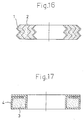
- FIG. 16 A first one of the volute type is shown in Fig. 16, in which a hoop member 1 made of SUS (stainless steel) or the like is rolled up as overlapping a filler member 2 such as a beater sheet of ceramic fibers.
- This gasket is fitted in annular concaves formed in either or both opposite surfaces of flanges for connecting exhaust pipes to each other, and both flanges are clamped and secured to each other with bolts, thus providing a seal between the opposite surfaces of the flanges.
- this gasket is of the metal jacket type in which a metallic line member made of SUS or the like is rolled up at a plurality of times to form a ring-like blank, the ring-like blank is uniformly pressed to form an annular center member 3, and the center member 3 is covered with a covering member 4 comprising a metallic thin plate made of SUS or the like.
- This gasket is fitted in an annular concave formed in one of the opposite surfaces of flanges for connecting exhaust pipes to each other. The flanges are clamped and secured to each other with bolts, thus providing a seal between the opposite surfaces of the flanges.
- this gasket is of the metallic knitted mesh type in which a tape-like member comprising a metallic knitted mesh and an inorganic material such as expanded graphite or the like inserted therein, is rolled up, and the resulting rolled body is put in molds and axially compression-molded.
- the filler member 2 together with the hoop member 1 is strongly clamped. Accordingly, if the gasket is low in density, sufficient sealing properties cannot be obtained. Further, the gasket cannot stand such a great clamping surface pressure. Accordingly, the gasket is generally made high in density, thus lacking flexibility.
- both the center member 3 and the covering member 4 are made of metal. Accordingly, the gasket lacks flexibility, resulting in poor adaptability with respect to the flange surfaces to be sealed, which exert a great influence to the sealing properties.
- each of such conventional gaskets in order to provide a predetermined sealing performance, it is required to remarkably increase a clamp load to be exerted at the time when the flanges are clamped with bolts, and to finish flat the flange surfaces to be sealed. That is, the flange surfaces to be sealed are made flat by machining means such as cutting of a forged product, which is disadvantageous in view of productivity and cost.
- the flanges themselves are required to be thick enough to stand a great clamp load, and the number of bolts to be used is required to be increased. This disadvantageously causes the exhaust pipe portions and the like of a motor vehicle using this gasket to be weighty.
- the conventional gasket of the metallic knitted mesh type is improved in rigidity and is therefore advantageous in view of handling convenience.
- the inserted metallic knitted mesh is moved to readily form leak passages of a fluid in the molded body of the inorganic material such as expanded graphite.
- portions of the molded body of the inorganic material such as expanded graphite or the like, are compressed and moved inwardly. This causes the metallic knitted mesh to be relatively exposed to the gasket surfaces.
- the exposed portions may come in contact with the flange surfaces to be sealed, or may be vibrated as coming in contact therewith.
- leak passages of a fluid are more readily formed. This disadvantageously remarkably lowers the sealing performance and readily causes the inorganic material to come off.
- the present invention is proposed with the object of providing a high-temperature resistant gasket which can exhibit, with a less clamp load, a sealing performance equal to or more than that of a conventional gasket, with the use of which the exhaust pipes and the like can be made lightweight, and which can be used with flanges mass-produced with less cost.
- the present invention provides a high-temperature resistant gasket comprising an annular base body made from a molded article of an inorganic substance, the annular base body being provided at each of the inner and outer peripheral surfaces thereof or at each of both axial end surfaces thereof with a covering layer made of a metallic mesh member integral with the base body.
- the annular base body is made from a molded article of an inorganic substance and is covered, at each of the inner and outer peripheral surfaces thereof or at each of both axial end surfaces thereof, with the metallic mesh member. Accordingly, while giving a suitable rigidity to the gasket, the gasket density can be readily controlled at the time of molding. In particular, when the base body is low in density, there can be readily obtained a gasket excellent in flexibility and adaptability with respect to flange surfaces to be sealed. Further, the metallic mesh member is integral with the base body. This not only prevents the base body and the metallic mesh member from being relatively moved at the time when vibration is exerted to the gasket, but also restrains the base body from creeping.
- the gasket can produce sealing properties equal to or more than those of a conventional gasket.
- the flange surfaces to be sealed may be roughly finished more or less. Therefore, there may be employed machining means such as pressing which is excellent in productivity and low in cost. Further, it is not required to thicken the flanges themselves in order to deal with a clamp load. Also, the number of bolts to be used can be reduced. Thus, the entire pipe connection parts can be made lightweight.
- the base body made from the molded article of the inorganic substance is covered, at each of the inner and outer peripheral surfaces thereof or at each of both axial end surfaces thereof, with a metallic mesh member.
- a metallic mesh member is made in a unitary structure. This prevents the base body made from the molded body of the inorganic substance from coming off and falling off due to vibration or an external force exerted at the time of replacement. This remarkably improves the entire gasket in durability.
- a metallic mesh may be disposed inside of the base body. In such an arrangement, the gasket can be further improved in handling convenience at the time of mounting or replacement thereof.
- the inorganic substance forming the base body may be selected from the group consisting of expanded graphite, mica, a beater sheet of cramic fibers and vermiculite. In such a case, by controlling the molding density, there can be readily produced a low-density base body.
- the gasket may be produced in the manner that: a tape of a metallic mesh member overlaps a tape of an inorganic substance forming the base body in the longitudinal direction thereof, the tape of the metallic mesh member being longer in length than the tape of the inorganic substance, the tape of the metallic mesh member having widths equal to and smaller than the width of the tape of the inorganic substance; the both tapes are rolled up; and the rolled body is molded in the form of a predetermined ring.
- the gasket may be produced in the manner that: a tape of a metallic mesh member overlaps a tape of an inorganic substance forming the base body at the center thereof in the longitudinal direction thereof, the tape of the metallic mesh member being wider in width and shorter in length than the tape of the inorganic substance; the both tapes are rolled up; both transverse ends of the tape of the metallic mesh member projecting from both transverse ends of the tape of the inorganic substance, are turned on both axial end surfaces of the rolled body; and the rolled body is molded in the form of a predetermined ring.
- the base member and the metalllic mesh member serving as a covering member can be readily and securely made in a unitary structure, and the base body can be covered at each of the inner and outer peripheral surfaces thereof or at each of the axial end surfaces thereof with the covering member in the course of the gasket producing process. Further, by suitably changing the length and width of each of the tape of the metallic mesh member and the tape of the inorganic substance forming the base body, the gasket may be optionally changed in section.
- annular projection may be formed at at least one of the axial end surfaces of the base body or at at least one of the inner and outer peripheral surfaces of the base body.
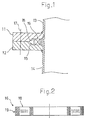
- Fig. 1 is a section view of a high-temperature resistant gasket of the present invention, illustrating how the gasket is mounted on connection parts of exhaust pipes.
- connection flanges 11, 12 are secured to exhaust pipes 13, 14 to be connected to each other, and an annular high-temperature resistant gasket 16 is fitted in annular concaves 15 formed in the opposite surfaces of the flanges 11, 12.
- the flanges 11, 12 are clamped and secured to each other at a plurality of circumferential positions thereof with bolts 17.
- Fig. 2 shows the arrangement of the high-temperature resistant gasket 16 fitted in the concaves 15.
- an annular base body 18 having a rectangular section is made from a molded article of an inorganic substance.
- the base body 18 is covered at each of the inner and outer peripheral surfaces thereof with a metallic mesh member 19. That is, the metallic mesh member 19 is rolled up in and together with the base body 18 so that the metallic mesh member 19 and the base body 18 are made in a unitary structure.
- the inorganic substance forming the base body 18 there is used one or more substances selected from the group consisting of expanded graphite, mica, a beater sheet of ceramic fibers and vermiculite.
- the metallic mesh member 19 may be made of, for example, SUS (stainless steel).
- a tape 18 made of expanded graphite As the inorganic substance forming the base body.
- the tape 19 has a narrow width at the center portion thereof, and a width equal to that of the expanded graphite tape 18, at each of the both ends of the tape 19.
- the tape 19 is longer than the expanded graphite tape 18.
- the knitted tape 19 of SUS 304 overlaps the expanded graphite tape 18 in the vicinity of the center thereof in the longitudinal direction thereof. From one end in the longitudinal direction, the knitted tape 19 is rolled up, and the expanded graphite tape 18 is also rolled up together with the knitted tape 19.
- an annular base body 18 in which the knitted tape 19 has been rolled up singly at the starting and terminating steps of the tape rolling operation, and in which the knitted tape 19 has been rolled up together with the expanded graphite tape 18 in the intermediate course of the tape rolling operation.
- the annular base body 18 is put between a center mold 20 and an outer mold 21 and pressed between a bottom mold 22 and a pressing mold 23.
- a gasket in which the annular base body 18 is covered at each of the inner and outer peripheral surfaces thereof with the metallic knitted tape 19 and in which the sealing portions adapted to be opposite to flanges, are made of expanded graphite.
- Fig. 6 is a schematic view of a basic device for measuring the amount of a fluid leaking through a sample of high-temperature resistant gasket.
- a pair of holding jigs 24, 25 are disposed for holding a sample of high-temperature resistant gasket M therebetween, and a casing body 26 is fitted on the holding jigs 24, 25.
- One holding jig 25 has a passage 27 through which a measuring fluid, for example N2 gas, passes and is injected inside of the gasket sample M.
- a measuring cylinder 29 Connected to a detection port 28 of the casing body 26 is a measuring cylinder 29 having a soapy water film for detecting the leakage of N2 gas through the gasket sample M.
- O-rings 30, 31 are interposed between the outer peripheral surfaces of the holding jigs 24, 25 and the inner peripheral surface of the casing body 26.
- the test for leakage amount above-mentioned may be conducted in a manner shown in Fig. 7, in which with one ends of exhaust pipes 13, 14 closed, a gasket sample is mounted between flanges 11, 12 of the exhaust pipes 13, 14.
- a flow meter 32 for air serving as a measuring fluid there may be used.
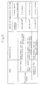
- each of the conventional gaskets of the volute type and of the metal jacket type could not restrain the leakage in the practically allowable range unless there was generated a clamping pressure as great as about 200 to about 340 kgf/cm2.
- the example of the present invention could restrain the leakage more effectively than each conventional gasket, with a clamping pressure of 120 Kgf/cm2 which was much smaller than that requried in each conventional gasket.
- a clamping pressure of 120 Kgf/cm2 which was much smaller than that requried in each conventional gasket.
- the expanded graphite tape forming the base body 18 is a molded article. More specifically, a low-density molded article can be readily formed by controlling the molding density, and it is possible to dispose layers of an inorganic substance liable to be readily fit to the contact surfaces of the flanges. This produces a good sealing effect.
- the flanges 11, 12 can be reduced in thickness and the number of bolts 17 to be used can be reduced. This contributes to reduction in weight of the exhaust pipe portions. Further, since high sealing properties can be obtained even with a small clamping pressure, it is not required that the opposite surfaces of the flanges 11, 12 are specially finished, but there may be used pressed articles as the flanges 11, 12.
- the knitted tape of SUS 304 serving as the covering member 19 is integrally rolled up in the expanded graphite tape forming the base body 18. Accordingly, the base body 18 is reinforced and therefore presents a suitable rigidity. This not only prevents the base body 18 from coming off, but also improves the base body in handling convenience and resistance to vibration.
- the base body 18 When removing the high-temperature resistant gasket 16 at the time of maintenance or the like, or when the high-temperature resistant gasket 16 is mounted on a part to be strongly vibrated, there is the likelihood that the base body 18 is rubbed and damaged at the inner and outer peripheral surfaces thereof, in particular at the ends of the inner and outer peripheral surfaces thereof.
- the base body 18 is covered with the covering member 19 of a SUS-304 knitted tape as mentioned earlier. This prevents such damages. Further, since the covering member 19 is integrated in the base body 18, there is no possibility of the covering member 19 being separated or coming off.
- the expanded graphite tape forming the base body 18 has the same length and the same width as those of the SUS-304 knitted tape serving as the covering member 19, and both the base body 18 and the covering member 19 are rolled up in the same width from the beginning to the end.
- a fluid to be sealed is liable to flow in the axial direction of the base body 18.
- the knitted tape is exposed to the axial end surfaces of the base body 18, such exposed portions are adapted to come in contact with the surfaces to be sealed when clamped. This causes a fluid to leak more readily.
- the base body 18 comprising the expanded graphite tape and the covering member 19 comprising the narrow-width knitted tape of SUS 304 are made in a unitary structure with the covering member 19 disposed only at the center portion of the base body 18.
- Such an arrangement remarkably reduces the leakage of a fluid in the axial direction of the base body 18. Further, this prevents the knitted tape from being exposed to the both axial ends of the base body 18, thus enabling the excellent sealing properties to be stably maintained for a long period of time.
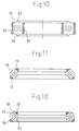
- Fig. 10 is a section view of a high-temperature resistant gasket according to a second embodiment of the present invention.
- the base body 18 comprising expanded graphite or the like is provided at each of both axial end surfaces thereof with an annular projection 33.
- the annular projection 33 may be formed at one of the axial end surfaces of the base body 18.
- a tape 18 made of expanded graphite as the inorganic substance forming the base body
- a tape 19 serving as the metallic mesh member as obtained by knittiong a line member of SUS 304 having a diameter of 0.15 mm, the tape 19 being wider and shorter than the expanded graphite tape 18.
- the inorganic substance forming the base body there are used one or more substances selected from the group consisting of expanded graphite, mica, a beater sheet of ceramic fibers and vermiculite.
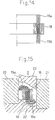
- the knitted tape 19 of SUS 304 overlaps the expanded graphite tape 18 in the vicinity of the center thereof in the longitudinal direction thereof. From one end in the longitudinal direction, the expanded graphite tape 18 is rolled up, and the knitted tape 19 is also rolled up together with the tape 18. Thus, there is formed an annular base body 18 in which the expanded graphite tape 18 has been rolled up singly at the starting and terminating steps of the rolling operation, and in which the expanded graphite tape 18 has been rolled up together with the knitted tape 19 in the intermediate course of the rolling operation. As shown in Fig. 14, the transverse ends 19a, 19b of the knitted tape 19 project from the base body 18 made of the expanded graphite tape, in the axial directions thereof.
- the base body 18 with the transverse ends 19a, 19b projecting therefrom is put between a center mold 20 and an outer mold 21 and pressed between a bottom mold 22 and a pressing mold 23.
- the base body 18 is covered at each of the axial end surfaces thereof with the knitted tape 19.
- Fig. 9 shows the results of room-temperature sealing tests, which represent the relationship between clamping surface pressure and leakage amount. More specifically, the tests were conducted on (i) an example of the gasket according to the second embodiment of the present invention and (ii) an example of the conventional gasket of the metallic knitted mesh type obtained in the manner that a tape-like member comprising a metallic knitted mesh and an inorganic material such as expanded graphite or the like inserted therein, was rolled up, and the rolled body was put in molds and axially compression-molded. With each of the gaskets fitted between opposite flange surfaces, nitrogen gas was caused to flow at 0.5 Kgf/cm2 in the connected pipes, and there were measured the clamping surface pressures and the leakage amounts.
- the leakage amounts are less by one digit, regardless of the clamping surface pressure value, than those of the example of the conventional gasket of the metal knitted mesh type.
- the leakage amount is remarkably restrained when the clamping surface pressure is small. This is because, in the conventional gasket of the metallic knitted mesh type, the metallic knitted mesh is exposed to the gasket surfaces which come in contact with the flanges, so that the fluid to be sealed is liable to leak.
- the gasket of the present invention can be applied to any of a variety of connection structures, in addition to flanged structures.
- the high-temperature resistant gasket of the present invention is improved in the materials and shapes of the annular base body and the covering member which covers each of the specific portions of the base body. Accordingly, without a great clamping pressure required, the gasket of the present invention can assure high sealing properties so that pipe connection parts can be made lightweight.
- the gasket of the present invention can be suitably used as a seal at connection parts of pipes through which any of a variety of high-temperature fluids passes.
- the gasket of the present invention can be suitably used as a seal device at connection parts of exhaust pipes in a motor vehicle.
Landscapes
- Engineering & Computer Science (AREA)
- General Engineering & Computer Science (AREA)
- Mechanical Engineering (AREA)
- Gasket Seals (AREA)
Applications Claiming Priority (1)
| Application Number | Priority Date | Filing Date | Title |
|---|---|---|---|
| PCT/JP1992/000482 WO1993021463A1 (en) | 1992-04-15 | 1992-04-15 | Gasket for high-temperature use |
Publications (3)
| Publication Number | Publication Date |
|---|---|
| EP0590149A1 true EP0590149A1 (de) | 1994-04-06 |
| EP0590149A4 EP0590149A4 (de) | 1994-10-19 |
| EP0590149B1 EP0590149B1 (de) | 1997-08-20 |
Family
ID=14042288
Family Applications (1)
| Application Number | Title | Priority Date | Filing Date |
|---|---|---|---|
| EP92908225A Expired - Lifetime EP0590149B1 (de) | 1992-04-15 | 1992-04-15 | Dichtung zum gebrauch bei hohen temperaturen |
Country Status (4)
| Country | Link |
|---|---|
| EP (1) | EP0590149B1 (de) |
| JP (1) | JP3286790B2 (de) |
| DE (1) | DE69221729T2 (de) |
| WO (1) | WO1993021463A1 (de) |
Cited By (1)
| Publication number | Priority date | Publication date | Assignee | Title |
|---|---|---|---|---|
| EP2801739A3 (de) * | 2013-05-10 | 2015-04-29 | FOCE Technology International B.V. | Dichtungsdrucksensor |
Families Citing this family (2)
| Publication number | Priority date | Publication date | Assignee | Title |
|---|---|---|---|---|
| JP6511349B2 (ja) * | 2015-07-01 | 2019-05-15 | 日本ピラー工業株式会社 | 排気管継手シール体 |
| JP7267782B2 (ja) * | 2019-03-07 | 2023-05-02 | 株式会社Ihi回転機械エンジニアリング | ガスケット及び流体装置 |
Family Cites Families (2)
| Publication number | Priority date | Publication date | Assignee | Title |
|---|---|---|---|---|
| JPS6123715Y2 (de) * | 1980-05-30 | 1986-07-16 | ||
| JPS5731975A (en) * | 1980-08-01 | 1982-02-20 | Chuo Spring Co Ltd | Molding method of heat-resistant gasket |
-
1992
- 1992-04-15 EP EP92908225A patent/EP0590149B1/de not_active Expired - Lifetime
- 1992-04-15 JP JP50777692A patent/JP3286790B2/ja not_active Expired - Fee Related
- 1992-04-15 WO PCT/JP1992/000482 patent/WO1993021463A1/ja active IP Right Grant
- 1992-04-15 DE DE69221729T patent/DE69221729T2/de not_active Expired - Fee Related
Non-Patent Citations (2)
| Title |
|---|
| No further relevant documents disclosed * |
| See also references of WO9321463A1 * |
Cited By (1)
| Publication number | Priority date | Publication date | Assignee | Title |
|---|---|---|---|---|
| EP2801739A3 (de) * | 2013-05-10 | 2015-04-29 | FOCE Technology International B.V. | Dichtungsdrucksensor |
Also Published As
| Publication number | Publication date |
|---|---|
| EP0590149A4 (de) | 1994-10-19 |
| DE69221729D1 (de) | 1997-09-25 |
| WO1993021463A1 (en) | 1993-10-28 |
| DE69221729T2 (de) | 1997-12-18 |
| JP3286790B2 (ja) | 2002-05-27 |
| EP0590149B1 (de) | 1997-08-20 |
Similar Documents
| Publication | Publication Date | Title |
|---|---|---|
| JP3112118B2 (ja) | 自動車排気系用の渦巻形ガスケット | |
| EP0590149B1 (de) | Dichtung zum gebrauch bei hohen temperaturen | |
| US5997007A (en) | Spiral wound type gasket | |
| EP0573383A1 (de) | Abdichtungselement | |
| EP0470830B1 (de) | Metallischer hohler O-Ring und Verfahren zu seiner Herstellung | |
| AU664905B2 (en) | Method for forming PTFE membrane/gasket assembly | |
| JP4172691B2 (ja) | 膨張黒鉛製シール材 | |
| JPS62155378A (ja) | 外周金属嵌合型オイルシール | |
| CN2339345Y (zh) | 薄板精密真空装焊胎具用的密封圈的改进 | |
| JP5336944B2 (ja) | 渦巻形ガスケット | |
| JP5031951B2 (ja) | 渦巻形ガスケット | |
| JP2568886B2 (ja) | 金属ガスケット | |
| JPS6043155A (ja) | エンジンオイルパンの取付方法 | |
| US3998347A (en) | Creep resistant sealing arrangement for bell jar | |
| JP2579175B2 (ja) | 金属ガスケット | |
| KR20030053060A (ko) | 냉각된 링 캐리어를 가지는 피스톤의 주조에 의한 제조방법 | |
| JPH09264427A (ja) | メタルガスケット | |
| JP2003194225A (ja) | 金属ガスケット | |
| JPH0221071A (ja) | シール装置 | |
| EP0803666A2 (de) | Spiralförmige Dichtung | |
| JP2001349435A (ja) | 自動緊塞ガスケット | |
| JPH0253671B2 (de) | ||
| JPH02194107A (ja) | 複合合金シリンダの製造方法 | |
| GB2344147A (en) | Encasing tubular component | |
| FI78772C (fi) | Ventil. |
Legal Events
| Date | Code | Title | Description |
|---|---|---|---|
| PUAI | Public reference made under article 153(3) epc to a published international application that has entered the european phase |
Free format text: ORIGINAL CODE: 0009012 |
|
| 17P | Request for examination filed |
Effective date: 19931112 |
|
| AK | Designated contracting states |
Kind code of ref document: A1 Designated state(s): DE FR GB |
|
| A4 | Supplementary search report drawn up and despatched | ||
| AK | Designated contracting states |
Kind code of ref document: A4 Designated state(s): DE FR GB |
|
| 17Q | First examination report despatched |
Effective date: 19960119 |
|
| GRAG | Despatch of communication of intention to grant |
Free format text: ORIGINAL CODE: EPIDOS AGRA |
|
| GRAH | Despatch of communication of intention to grant a patent |
Free format text: ORIGINAL CODE: EPIDOS IGRA |
|
| GRAH | Despatch of communication of intention to grant a patent |
Free format text: ORIGINAL CODE: EPIDOS IGRA |
|
| GRAA | (expected) grant |
Free format text: ORIGINAL CODE: 0009210 |
|
| AK | Designated contracting states |
Kind code of ref document: B1 Designated state(s): DE FR GB |
|
| ET | Fr: translation filed | ||
| REF | Corresponds to: |
Ref document number: 69221729 Country of ref document: DE Date of ref document: 19970925 |
|
| PGFP | Annual fee paid to national office [announced via postgrant information from national office to epo] |
Ref country code: GB Payment date: 19980401 Year of fee payment: 7 |
|
| PGFP | Annual fee paid to national office [announced via postgrant information from national office to epo] |
Ref country code: FR Payment date: 19980417 Year of fee payment: 7 |
|
| PGFP | Annual fee paid to national office [announced via postgrant information from national office to epo] |
Ref country code: DE Payment date: 19980428 Year of fee payment: 7 |
|
| PLBE | No opposition filed within time limit |
Free format text: ORIGINAL CODE: 0009261 |
|
| STAA | Information on the status of an ep patent application or granted ep patent |
Free format text: STATUS: NO OPPOSITION FILED WITHIN TIME LIMIT |
|
| 26N | No opposition filed | ||
| PG25 | Lapsed in a contracting state [announced via postgrant information from national office to epo] |
Ref country code: GB Free format text: LAPSE BECAUSE OF NON-PAYMENT OF DUE FEES Effective date: 19990415 |
|
| GBPC | Gb: european patent ceased through non-payment of renewal fee |
Effective date: 19990415 |
|
| PG25 | Lapsed in a contracting state [announced via postgrant information from national office to epo] |
Ref country code: FR Free format text: LAPSE BECAUSE OF NON-PAYMENT OF DUE FEES Effective date: 19991231 |
|
| REG | Reference to a national code |
Ref country code: FR Ref legal event code: ST |
|
| PG25 | Lapsed in a contracting state [announced via postgrant information from national office to epo] |
Ref country code: DE Free format text: LAPSE BECAUSE OF NON-PAYMENT OF DUE FEES Effective date: 20000201 |