EP0588596B1 - Raccord de tuyaux, également en combinaison avec un outil de démontage - Google Patents
Raccord de tuyaux, également en combinaison avec un outil de démontage Download PDFInfo
- Publication number
- EP0588596B1 EP0588596B1 EP93307229A EP93307229A EP0588596B1 EP 0588596 B1 EP0588596 B1 EP 0588596B1 EP 93307229 A EP93307229 A EP 93307229A EP 93307229 A EP93307229 A EP 93307229A EP 0588596 B1 EP0588596 B1 EP 0588596B1
- Authority
- EP
- European Patent Office
- Prior art keywords
- tubular member
- wall portion
- lock ring
- assembly according
- annular
- Prior art date
- Legal status (The legal status is an assumption and is not a legal conclusion. Google has not performed a legal analysis and makes no representation as to the accuracy of the status listed.)
- Expired - Lifetime
Links
- 230000008878 coupling Effects 0.000 title claims description 19
- 238000010168 coupling process Methods 0.000 title claims description 19
- 238000005859 coupling reaction Methods 0.000 title claims description 19
- 238000007789 sealing Methods 0.000 claims description 13
- 239000002131 composite material Substances 0.000 claims description 6
- 238000003780 insertion Methods 0.000 claims description 5
- 230000037431 insertion Effects 0.000 claims description 5
- 239000000463 material Substances 0.000 claims description 4
- 230000006835 compression Effects 0.000 claims description 3
- 238000007906 compression Methods 0.000 claims description 3
- 230000000149 penetrating effect Effects 0.000 claims description 2
- 239000012530 fluid Substances 0.000 description 4
- 239000000853 adhesive Substances 0.000 description 3
- 230000001070 adhesive effect Effects 0.000 description 3
- 239000002184 metal Substances 0.000 description 3
- 229910052751 metal Inorganic materials 0.000 description 3
- 238000000034 method Methods 0.000 description 3
- 239000004033 plastic Substances 0.000 description 3
- 230000000712 assembly Effects 0.000 description 2
- 238000000429 assembly Methods 0.000 description 2
- 230000035515 penetration Effects 0.000 description 2
- 238000005476 soldering Methods 0.000 description 2
- 238000003466 welding Methods 0.000 description 2
- 230000015556 catabolic process Effects 0.000 description 1
- 239000013043 chemical agent Substances 0.000 description 1
- 238000006731 degradation reaction Methods 0.000 description 1
- 238000005868 electrolysis reaction Methods 0.000 description 1
- 230000002708 enhancing effect Effects 0.000 description 1
- 150000002739 metals Chemical class 0.000 description 1
- 230000005012 migration Effects 0.000 description 1
- 238000013508 migration Methods 0.000 description 1
- 238000009428 plumbing Methods 0.000 description 1
- 238000000926 separation method Methods 0.000 description 1
- 238000007493 shaping process Methods 0.000 description 1
- 229920001169 thermoplastic Polymers 0.000 description 1
- 239000004416 thermosoftening plastic Substances 0.000 description 1
- XLYOFNOQVPJJNP-UHFFFAOYSA-N water Substances O XLYOFNOQVPJJNP-UHFFFAOYSA-N 0.000 description 1
Images


Classifications
-
- F—MECHANICAL ENGINEERING; LIGHTING; HEATING; WEAPONS; BLASTING
- F16—ENGINEERING ELEMENTS AND UNITS; GENERAL MEASURES FOR PRODUCING AND MAINTAINING EFFECTIVE FUNCTIONING OF MACHINES OR INSTALLATIONS; THERMAL INSULATION IN GENERAL
- F16L—PIPES; JOINTS OR FITTINGS FOR PIPES; SUPPORTS FOR PIPES, CABLES OR PROTECTIVE TUBING; MEANS FOR THERMAL INSULATION IN GENERAL
- F16L37/00—Couplings of the quick-acting type
- F16L37/08—Couplings of the quick-acting type in which the connection between abutting or axially overlapping ends is maintained by locking members
- F16L37/084—Couplings of the quick-acting type in which the connection between abutting or axially overlapping ends is maintained by locking members combined with automatic locking
- F16L37/092—Couplings of the quick-acting type in which the connection between abutting or axially overlapping ends is maintained by locking members combined with automatic locking by means of elements wedged between the pipe and the frusto-conical surface of the body of the connector
- F16L37/0925—Couplings of the quick-acting type in which the connection between abutting or axially overlapping ends is maintained by locking members combined with automatic locking by means of elements wedged between the pipe and the frusto-conical surface of the body of the connector with rings which bite into the wall of the pipe
Definitions
- the invention relates generally to an improved pipe coupling assembly and, more particularly, to an easily assembled and disassembled pipe coupling assembly, also in combination with a disengagement tool.
- Non-metallic pipe such as thermoplastic pipe, may also be joined by adhesives.
- the invention is directed to a coupling assembly of the general type disclosed in US-A-4,068,866, for use in connecting one end of a first tubular member to a component of a piping system, which comprises: a receiving tubular member on said component and defining an opening adapted to receive said first tubular member, said receiving tubular member having an inner portion defining an inner bore dimensioned to receive said one end and an outer portion defining an internal annular cavity intersecting said inner bore and projecting radially outwardly therefrom, said annular cavity comprising an annular tapered wall portion tapered radially inwardly and projecting longitudinally toward said opening; a split lock ring formed from spring material having a substantially circular cross-section and disposed in said annular cavity between said first tubular member and said receiving tubular member, said lock ring having an outer circumferential surface portion adapted to engage said tapered wall portion and an inner circumferential surface portion adapted to engage an external wall portion of said first tubular member, said lock ring being adapted to expand circumferentially into said
- the prior coupling assemblies each employ a lock ring which has a relatively complex cross-section that requires shaping to fit the shape of the recess in which it sits.
- the object of this invention is to provide a simplified and less costly pipe coupling assembly, as well as an assembly that can be easily assembled and disassembled by unskilled workers.
- the coupling assembly is characterised in that: the locking ring has a circular cross-section except that said inner circumferential surface portion includes a knife edge comprising a circumferential edge formed by a circumferential groove in said lock ring for penetrating said external wall portion of said first tubular member so as to prevent said longitudinal separating movement between said first tubular member and said receiving tubular member.
- the circumferential groove in the lock ring defines one wall terminated by the circumferential edge and oriented substantially perpendicular to the external wall portion of the first tubular member, and another wall substantially perpendicular to the one wall and extending between the one wall and an outer surface of the lock ring.
- An effective knife edge is formed by the one and another walls.
- the lock ring has an inner diameter less than the outer diameter of the first tubular member, has first and second ends normally axially displaced, and the first and second ends are forced into substantial alignment in response to compression of the lock ring between the tapered wall portion and the external wall portion.
- the spring characteristics of the split ring facilitate its expansion into the annular cavity and create a longitudinally directed force that restricts movement of the first tubular member into the receiving tubular member.
- the assembly includes an auxiliary ring having separated ends and disposed in the annular cavity between said lock ring and the sealing member, the auxiliary ring being engaged between an inner surface of the cavity and the external wall portion, and an inner circumference of the auxiliary ring defining longitudinal edges projecting substantially parallel to a longitudinal axis of the first tubular member and adapted to penetrate the outer surface thereof.
- the auxiliary ring prevents rotation of the first tubular member within the receiving tubular member.
- the annular cavity further comprises a cylindrical wall portion extending between the tapered wall portion and the inner bore, the auxiliary ring and the sealing member are adapted for engagement between the cylindrical wall portion and the first tubular member, and the lock ring is dimensioned so as to prevent engagement thereof with the cylindrical wall portion during its circumferential expansion by the first tubular member.
- the tapered wall portion terminates with a radially inwardly directed rim forming a shoulder stop portion at an outer end of the receiving tubular member, and the stop portion is adapted to engage the lock ring in response to the separating movement.
- the stop portion positively retains the lock ring within the completed assembly.
- the invention also encompasses a disengagement tool in combination with the above assembly and including first and second arcuately shaped parts attached by a flexible connector and each having a longitudinally extending inner cylindrical surface conforming to the outer surface of the first tubular member and adapted for engagement therewith in a juxtaposed relationshiptoform a composite outer tube, the composite outer tube being adapted for sliding movement on the first tubular member and having an actuator annular end adapted to be pushed through the opening into the annular cavity and into forcible engagement with the lock ring so as to cause circumferential expansion thereof.
- the disengagement tool eliminates engagement between the knife edge and the first tubular member to permit removal thereof.
- a pipe coupling assembly 11 including an inner first tubular member 12 and an outer receiving tubular member 13.
- the tubular member 12 generally will be a length of pipe or tubing such as commonly employed for the delivery of fluids.
- the embracing tubular member 13 will generally form a part of a pipe fitting, such as an elbow, tee, or the like, or will form a part of some other component of a piping system, such as a valve.
- the receiving tubular member 13 includes an inner portion 14, an outer portion 15 and an end portion 16 with a radially inwardly directed rim 18 that defines a circular opening 17 and an inwardly directed shoulder 19.
- an inner bore 21 dimensioned to snugly receive the outer surface of the first tubular member 12.
- the outer portion 15 of the receiving tubular member 13 defines an annular cavity 22 intercepting the inner bore 21 and projecting radially outwardly therefrom.
- Forming the annular cavity 22 is a cylindrical wall portion 24 and an annular' tapered wall portion 25 joining the cylindrical wall portion 24 and the shoulder 19 surrounding the opening 17.
- An annular gap 27 is formed between the first tubular member 12 and the rim 17 which has a diameter larger than the outer surface of the member 12.
- annular shoulder 28 on the receiving tubular member 13 is a counterbore 29.
- An annular rib 31 on the receiving tubular member 13 projects inwardly from the cylindrical portion 24 and separates the cavity 22 into longitudinally separated cavity portions 32 and 33.
- Projecting inwardly from the cylindrical wall portion 24 in the cavity portion 32 is a longitudinally disposed ridge 34.
- the pipe coupling assembly 11 also includes a split lock ring 35 disposed in the cavity portion 32, a sealing member 36 such as a resilient O-ring disposed in the cavity portion 33, and a split auxiliary ring 37 disposed in the cavity portion between the lock ring 35 and the annular rib 31.
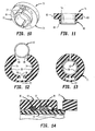
- the lock ring 35 is made from a material suitable to establish a good spring characteristic. As shown in Figs. 3-5, the lock ring 35 has a circular cross-section, an outer circumferential surface portion 41 of diameter D less than the diameter of the adjacent cylindrical wall portion 24, and an inner circumferential surface portion 42 of diameter d less than the outer diameter of the first tubular member 12. Cut in the inner surface portion 42 is a circumferential groove 44 formed by one wall 43 oriented perpendicular to an outer surface 45 of the first tubular member 12, and another wall 47 extending between the outer surface of the ring 35 and the one wall 43 and oriented perpendicular thereto. The another wall 47 extends from the one wall 43 away from the opening 17 in the tubular member 13.
- a circumferential knife edge 48 Formed by the periphery of the one wall 43 is a circumferential knife edge 48 extending parallel to the outer surface 45 of the first tubular member 12.
- First and second ends 51, 52 of the lock ring 35 straddle a split therein and, as shown in Fig. 3, the second end 52 is axially displaced from the first end 51 which is circumferentially aligned with the major portion of the ring 35.
- the auxiliary ring 37 also is formed from a suitable spring material and has separated ends 54, 55 straddling a gap 56.
- An outer circumference 61 of the auxiliary ring 37 engages the cylindrical surface portion 24 of the cavity portion 32.
- Cut into an inner circumference 62 are circumferentially spaced apart teeth 63 that form longitudinally disposed edges 64 oriented parallel to the axis of the first tubular member 12.
- the first tubular member 12 is inserted through the opening 17 in the receiving tubular member 13 as shown in Fig. 8, until an inner end 68 of the member 12 engages the annular shoulder 28.
- the first tubular member 12 moves through the annular cavity 22, its external surface engages the knife edge inner surface 48 of the lock ring 35 expanding it outwardly into the cavity portion 32 of the annular cavity 22.
- the outer diameter D of the lock ring 35 is less than that of the cylindrical wall portion 24, inward axial movement of the first tubular member 12 is not restricted.
- the auxiliary ring 37 is compressed between the cylindrical surface portion 24 and the outer surface of the first tubular member 12, which outer surface is scored by the longitudinal projecting edges 64.
- a tapered annular transitional surface 69 between the cylindrical surface portion 24 and the inner bore 21 accommodates longitudinal migration of the sealing member 36 so as to prevent damage thereto during insertion of the first tubular member 12 as shown in Fig. 8.
- the first tubular member 12 is partially withdrawn to produce a longitudinal separation movement relative to the receiving tubular member 13.
- the lock ring 35 is forced longitudinally outwardly in the annular cavity 22 and tightly compressed therein between the shoulder stop 19, the tapered wall portion 25 and the outer surface of the first tubular member 12 as shown in Fig. 9. Because of the penetration of the outer surface of the first tubular member 12 by the knife edge 48 on the lock ring 35, further relative longitudinal movement between the member 12 and the receiving tubular member 13 is prevented.
- the second end 52 of the lock ring 35 is forced into circumferential alignment with the first end 51 creating an axially directed force that biases the member 12 inwardly in the member 13.
- Fluid pressure within the coupling 11 exerts on the first member 12 a longitudinally outwardly directed force F that is transferred by the tapered wall portion 25 radially inwardly on the lock ring 35. Consequently, the knife edge 48 is driven further into the outer surface of the first member 12 and enhancing the securement thereof to the receiving member 13.
- the O-ring 36 is engaged between the cylindrical surface portion 24 and the outer surface of the first tubular member 12 to create a fluid tight seal therebetween.
- the anniilar rib 31 prevents damage of the annular sealing member 36 by the teeth 63 on the auxiliary ring 37.
- the disengagement tool 51 consists of first and second identically shaped arcuate parts 72, 73, respectively.
- Each of the parts 72, 73 has a longitudinally extending inner cylindrical surface 74 conforming to the outer surface of the first tubular member 12.
- One end 75 of the part 72 is connected to one end 76 of the part 73 by a flexible connection portion 77 that permits relative pivotal movement therebetween as shown in Fig. 12.
- the parts 72, 73 When positioned on the outer surface of the first tubular member 12, the parts 72, 73 form a composite tube 78 that defines an outer actuator end 80 having an outwardly facing, annular tapered surface 81.
- Extending radially outwardly from each of the parts 72, 73 is a shoulder or flange portion 82, 83, respectively.
- the opposite ends 84, 85 of the parts 72, 73, respectively, are separated as shown in Fig. 12 allowing the tool 71 to be positioned around the member 12 with the surfaces 74 engaging the outer surface thereof.
- the flange portions 82, 83 of the parts 72, 73 are pushed to produce sliding movement of the cylindrical surfaces 74 on the outer surface of the first tubular member 12. That sliding movement is continued to move the annular actuator end 80 of the composite tube 78 through the annular gap 27 until the flange portions 82, 83 engage the outer end 16 of the receiving tubular member 13.
- the annular tapered surface 81 engages and forces the lock ring 35 into an inward position as shown in Fig. 14.
Claims (18)
- Assemblage de couplage destiné à être utilisé pour connecter une extrémité d'un premier élément tubulaire (12) à un composant d'un système de tuyauterie, ledit assemblage (11) comprenant :un élément tubulaire de réception (13) sur ledit composant et définissant une ouverture (17) destinée à recevoir ledit premier élément tubulaire (12), ledit élément tubulaire de réception ayant une partie interne (14) définissant un alésage interne (21) dimensionné pour recevoir ladite une extrémité et une partie externe (15) définissant une cavité annulaire interne (22) coupant ledit alésage interne et se projetant radialement vers l'extérieur à partir de celui-ci, ladite cavité annulaire comprenant une partie de paroi annulaire conique (25) s'évasant radialement vers l'intérieur et se projetant longitudinalement en direction de ladite ouverture (17) ;un anneau de verrouillage fendu (35) formé à partir d'un matériau à ressort et disposé dans ladite cavité annulaire (22) entre ledit premier élément tubulaire (12) et ledit élément tubulaire de réception (13), ledit anneau de verrouillage (35) ayant une partie de surface circonférentielle externe (41) adaptée à venir en prise avec ladite partie de paroi conique (25) et une partie de surface circonférentielle interne (42) adapté à venir en prise avec une partie de paroi externe (45) dudit premier élément tubulaire, ledit anneau de verrouillage étant adapté à s'agrandir circonférentiellement dans ladite cavité annulaire pendant l'insertion dudit premier élément tubulaire dans ledit élément tubulaire de réception et à être comprimé entre ladite partie de paroi conique (25) et ladite partie de paroi externe (45) en réponse à un mouvement relatif de séparation longitudinale entre ledit premier élément tubulaire et ledit élément tubulaire de réception de telle manière à empêcher un mouvement longitudinal dudit premier élément tubulaire par rapport audit élément tubulaire de réception ; etun élément d'étanchéité annulaire (36) disposé dans ladite cavité annulaire (22) entre ledit anneau de verrouillage (35) et ledit alésage interne (21), ledit élément d'étanchéité étant dimensionné pour venir en prise entre ledit élément tubulaire et ledit élément tubulaire de réception ;caractérisé en ce que :
ledit anneau de verrouillage (35) a une section transversale circulaire excepté que ladite partie de surface circonférentielle interne (42) comprend une arête vive comprenant une arête circonférentielle (48) formée par une rainure circonférentielle (44) dans ledit anneau de verrouillage pour pénétrer dans ladite partie de paroi externe (45) dudit premier élément tubulaire de telle manière à empêcher ledit mouvement de séparation longitudinal entre ledit élément tubulaire (12) et ledit élément tubulaire de réception (13). - Assemblage selon la revendication 1, dans lequel ladite rainure (44) définit une paroi (43) terminée par ladite arête circonférentielle (48) et orientée transversalement à ladite partie de paroi externe (45).
- Assemblage selon la revendication 2, dans lequel ladite une paroi (43) est sensiblement perpendiculaire à ladite partie de paroi externe (45).
- Assemblage selon la revendication 1, 2 ou 3, dans lequel ladite rainure (44) définit en outre une autre paroi (47) s'étendant entre ladite une paroi (43) et une surface externe dudit anneau de verrouillage (35).
- Assemblage selon la revendication 4, dans lequel ladite autre paroi (47) est sensiblement perpendiculaire à ladite une paroi (43).
- Assemblage selon l'une quelconque des revendications précédentes, dans lequel ledit anneau de verrouillage (35) comporte des première et seconde extrémités (51, 52) déplaçables normalement axialement et lesdites première et seconde extrémités sont forcées en alignement substantiel en réponse à une compression dudit anneau de verrouillage entre ladite partie de paroi conique (25) et ladite partie de paroi externe (45).
- Assemblage selon l'une quelconque des revendications précédentes, dans lequel ledit anneau de verrouillage (35) comporte un diamètre interne inférieur au diamètre externe dudit premier élément tubulaire.
- Assemblage selon l'une quelconque des revendications précédentes, comprenant un anneau auxiliaire (37) disposé dans ladite cavité annulaire (22) entre ledit anneau de verrouillage (35) et ledit élément d'étanchéité (36), ledit anneau auxiliaire étant en prise entre une surface interne (24) de ladite cavité et ladite partie de paroi externe, et dans lequel une circonférence interne (62) dudit anneau auxiliaire définit des arêtes longitudinales (63) se projetant sensiblement parallèlement à un axe longitudinal dudit premier élément tubulaire et adapté à pénétrer dans la surface externe de celui-ci.
- Assemblage selon la revendication 8, dans lequel ledit anneau auxiliaire (37) est un anneau fendu ou coupé ayant des extrémités séparées (54, 55).
- Assemblage selon la revendication 9, dans lequel ladite cavité annulaire (22) comprend une nervure longitudinale (34), et les extrémités séparées (51, 52 ; 54, 55) des anneaux de verrouillage et auxiliaire (35 ; 37) sont disposées sur de côtés opposés de ladite nervure.
- Assemblage selon la revendication 8, 9 ou 10, dans lequel ledit élément tubulaire de réception définit une nervure annulaire (31) se projetant radialement dans ladite cavité annulaire (22) et disposé entre ledit anneau auxiliaire (37) et ledit élément d'étanchéité (36).
- Assemblage selon l'une quelconque des revendications 8 à 11, dans lequel ladite cavité annulaire (22) comprend en outre une partie de paroi cylindrique (24) s'étendant entre ladite partie de paroi conique (25) et ledit alésage interne (21), ledit anneau auxiliaire (37) et ledit élément d'étanchéité (36) sont adaptés pour venir en prise entre ladite partie de paroi cylindrique et ledit premier élément tubulaire.
- Assemblage selon la revendication 12, dans lequel ledit élément tubulaire de réception définit en outre une partie de paroi de transition annulaire (69) qui est conique entre ladite partie de paroi cylindrique (24) et ledit alésage interne (21).
- Assemblage selon la revendication 12 ou 13, dans lequel ledit anneau de verrouillage (35) est dimensionné de telle manière à empêcher qu'il vienne en prise avec ladite partie de paroi cylindrique (24) pendant ledit agrandissement circonférentiel par ledit premier élément tubulaire.
- Assemblage selon l'une quelconque des revendications précédentes, dans lequel ladite partie de paroi conique (25) se termine avec un bord (18) dirigé radialement vers l'intérieur formant une partie d'épaulement d'arrêt (18) à une extrémité externe dudit élément tubulaire de réception, et ladite partie d'arrêt est adaptée à venir en prise avec ledit anneau de verrouillage en réponse audit mouvement de séparation.
- Assemblage de couplage selon l'une quelconque des revendications précédentes, en combinaison avec un outil de démontage (71) comprenant :
des première et seconde parties de forme arquée (72, 73) fixées par un connecteur flexible (77) et ayant chacune une surface cylindrique interne s'étendant longitudinalement (74) se conformant à la surface externe dudit premier élément tubulaire (12) et adapté à venir en prise avec celui-ci dans une relation juxtaposée pour former un tube externe composite, ledit tube externe composite étant adapté pour un mouvement de glissement sur ledit premier élément tubulaire et ayant une extrémité annulaire d'actionnement (80) adaptée à être poussée à travers ladite ouverture (17) dans ladite cavité annulaire (22) et en prise forcée avec ledit anneau de verrouillage (35) de telle manière à entraîner son agrandissement circonférentiel et par conséquent à éliminer la prise entre ladite arête vive (48) et ledit premier élément tubulaire (12). - Combinaison d'assemblage et d'outil selon la revendication 16, dans laquelle ladite extrémité annulaire (80) de l'outil comprend une surface annulaire conique (81).
- Combinaison d'assemblage et d'outil selon la revendication 17, dans laquelle chacune desdites parties de l'outil définit une partie d'épaulement s'étendant radialement vers l'extérieur (82, 83).
Applications Claiming Priority (2)
| Application Number | Priority Date | Filing Date | Title |
|---|---|---|---|
| US07/944,373 US5328215A (en) | 1992-09-14 | 1992-09-14 | Pipe joint assembly |
| US944373 | 1992-09-14 |
Publications (2)
| Publication Number | Publication Date |
|---|---|
| EP0588596A1 EP0588596A1 (fr) | 1994-03-23 |
| EP0588596B1 true EP0588596B1 (fr) | 1997-07-16 |
Family
ID=25481277
Family Applications (1)
| Application Number | Title | Priority Date | Filing Date |
|---|---|---|---|
| EP93307229A Expired - Lifetime EP0588596B1 (fr) | 1992-09-14 | 1993-09-14 | Raccord de tuyaux, également en combinaison avec un outil de démontage |
Country Status (5)
| Country | Link |
|---|---|
| US (1) | US5328215A (fr) |
| EP (1) | EP0588596B1 (fr) |
| JP (1) | JP3646185B2 (fr) |
| CA (1) | CA2106120A1 (fr) |
| DE (1) | DE69312194T2 (fr) |
Families Citing this family (32)
| Publication number | Priority date | Publication date | Assignee | Title |
|---|---|---|---|---|
| GB9314094D0 (en) * | 1993-07-08 | 1993-08-18 | Angell Jonathan G C | Releasable coupling |
| US5496073A (en) * | 1993-11-29 | 1996-03-05 | Rovac Corporation | Disengagement tool for use with a pipe joint assembly |
| AU684975B2 (en) * | 1994-06-28 | 1998-01-08 | Eisenwerke Fried. Wilh. Duker Gmbh & Co. | Tension-resisting pipe connection and method of making same |
| DE4430858A1 (de) * | 1994-06-28 | 1996-03-07 | Ritz Reinert Gmbh | Zugfeste Rohrverbindung und Verfahren zu ihrer Herstellung |
| US5820167A (en) * | 1995-12-22 | 1998-10-13 | Kelsey-Hayes Company | Quick-connect arrangement for high density hydraulic lines for anti-lock brake and/or traction control systems |
| AU3612399A (en) * | 1998-02-28 | 1999-09-15 | Linkindex Limited | Pipe connection system |
| JP2001193885A (ja) * | 1999-11-05 | 2001-07-17 | Togo Seisakusho Corp | 管継手 |
| US7108289B1 (en) | 2000-06-08 | 2006-09-19 | United States Pipe And Foundry Company, Llc | Restraining gasket for mechanical joints of pipes |
| US7104573B2 (en) * | 2000-06-08 | 2006-09-12 | United States Pipe And Foundy Company, Llc | Energized restraining gasket for mechanical joints of pipes |
| US6568658B2 (en) | 2000-12-22 | 2003-05-27 | Craneveyor Corporation | Quick-connect railing connector |
| US6688652B2 (en) * | 2001-12-12 | 2004-02-10 | U.S. Pipe And Foundry Company | Locking device and method for securing telescoped pipe |
| US7021672B2 (en) * | 2003-05-29 | 2006-04-04 | Orbit Irrigation Products, Inc. | Irrigation coupling apparatus and method |
| US20090160178A1 (en) * | 2003-05-29 | 2009-06-25 | Ericksen Kent C | Centering system for coupling for irrigation system |
| US9604404B2 (en) | 2003-05-29 | 2017-03-28 | Orbit Irrigation Products, Inc. | Conduit coupling apparatus and method |
| US9429262B2 (en) | 2003-05-29 | 2016-08-30 | Orbit Irrigation Products, Inc. | Conduit coupling apparatus and method |
| US20090160179A1 (en) * | 2003-05-29 | 2009-06-25 | Ericksen Kent C | Coupling release mechanism for irrigation system |
| US7137653B2 (en) * | 2003-09-25 | 2006-11-21 | United States Pipe And Foundry Company, Llc | Centroidally twistable compression ring for pipe joints |
| AU2003279379A1 (en) * | 2003-11-11 | 2005-06-17 | Hans Oetiker Ag Maschinen- Und Apparatefabrik | Quick-fit coupling |
| NO20051920L (no) * | 2005-04-20 | 2006-10-23 | Kongsberg Automotive As | Utloserklips. |
| CA2614127A1 (fr) * | 2005-07-03 | 2007-01-11 | Widee B.V. | Accouplement entre deux tubes |
| US20100171302A1 (en) * | 2009-01-05 | 2010-07-08 | Nibco Inc. | Push-twist connector |
| GB201104229D0 (en) * | 2011-03-14 | 2011-04-27 | Harris Andrew D | Pipe fittings |
| US11384872B1 (en) | 2011-05-24 | 2022-07-12 | Husqvarna Ab | Conduit coupling apparatus and method |
| US9086179B1 (en) * | 2011-06-16 | 2015-07-21 | Naris Komolrochanaporn | Quick coupling pipe fitting system |
| USD732359S1 (en) | 2012-08-21 | 2015-06-23 | Orbit Irrigation Products, Inc. | Conduit removal tool |
| US9541228B2 (en) | 2013-12-11 | 2017-01-10 | Nibco Inc. | Push-to-connect fitting |
| US9447906B2 (en) | 2013-12-11 | 2016-09-20 | Nibco Inc. | Self-locking push-to-connect insert |
| US10006575B2 (en) | 2013-12-11 | 2018-06-26 | Nibco Inc. | Modular push-to-connect assembly |
| US9777875B2 (en) | 2014-02-26 | 2017-10-03 | Nibco Inc. | Clam shell push-to-connect assembly |
| US10161551B2 (en) | 2015-07-09 | 2018-12-25 | A. Raymond Et Cie | Quick-connector |
| US9964243B1 (en) * | 2017-03-23 | 2018-05-08 | Wen Sheng Fu Co. Ltd. | Pipe joint structure |
| US11267236B2 (en) * | 2018-03-16 | 2022-03-08 | Divergent Technologies, Inc. | Single shear joint for node-to-node connections |
Family Cites Families (14)
| Publication number | Priority date | Publication date | Assignee | Title |
|---|---|---|---|---|
| US2478127A (en) * | 1944-12-14 | 1949-08-02 | Parker Appliance Co | Emergency repair coupling |
| DE1954247A1 (de) * | 1969-10-28 | 1971-05-06 | Georg Seiler | Schubsicherung der Steckmuffenverbindung bei Druckrohren bzw. Formstuecken |
| DE2034325C3 (de) * | 1970-07-10 | 1974-03-07 | Georg 8000 Muenchen Seiler | Zug- und Schubsicherung für Steckmuffen- Verbindungen |
| US3815940A (en) * | 1971-07-22 | 1974-06-11 | Mueller Co | Joint for smooth end or flareless pipe |
| US4068866A (en) * | 1976-03-25 | 1978-01-17 | Mueller Co. | Stab-type joint for smooth end or flareless pipe |
| DE2851661A1 (de) * | 1978-11-29 | 1980-06-12 | Michigan Hanger Co | Rohrverbinder |
| US4586734A (en) * | 1982-12-08 | 1986-05-06 | General Industries, Inc. | Pipe joint assembly |
| GB2166508B (en) * | 1984-11-05 | 1989-04-05 | Paragon Plastics Limited | Pipe joints |
| LU86357A1 (fr) * | 1986-03-14 | 1987-11-11 | Buchholz Fernand | Bague pour raccord aut-bloquant et raccord auto-bloquant comportant une telle bague et destine notamment a des tubes en matiere plastique |
| JP2561694B2 (ja) * | 1988-03-26 | 1996-12-11 | 積水化学工業株式会社 | 管継手 |
| JP2547237B2 (ja) * | 1988-03-26 | 1996-10-23 | 積水化学工業株式会社 | 管継手 |
| JP2563986B2 (ja) * | 1988-08-09 | 1996-12-18 | 積水化学工業株式会社 | 管継手 |
| JPH0251693A (ja) * | 1988-08-09 | 1990-02-21 | Sekisui Chem Co Ltd | 管継手 |
| DE4134089C2 (de) * | 1991-10-15 | 1994-10-13 | Dueker Eisenwerk | Schubgesicherte Muffenverbindung |
-
1992
- 1992-09-14 US US07/944,373 patent/US5328215A/en not_active Expired - Lifetime
-
1993
- 1993-09-14 JP JP25229193A patent/JP3646185B2/ja not_active Expired - Fee Related
- 1993-09-14 CA CA002106120A patent/CA2106120A1/fr not_active Abandoned
- 1993-09-14 EP EP93307229A patent/EP0588596B1/fr not_active Expired - Lifetime
- 1993-09-14 DE DE69312194T patent/DE69312194T2/de not_active Expired - Fee Related
Also Published As
| Publication number | Publication date |
|---|---|
| DE69312194D1 (de) | 1997-08-21 |
| JPH06193786A (ja) | 1994-07-15 |
| DE69312194T2 (de) | 1998-02-19 |
| US5328215A (en) | 1994-07-12 |
| CA2106120A1 (fr) | 1994-03-15 |
| JP3646185B2 (ja) | 2005-05-11 |
| EP0588596A1 (fr) | 1994-03-23 |
Similar Documents
| Publication | Publication Date | Title |
|---|---|---|
| EP0588596B1 (fr) | Raccord de tuyaux, également en combinaison avec un outil de démontage | |
| US5496073A (en) | Disengagement tool for use with a pipe joint assembly | |
| US4586734A (en) | Pipe joint assembly | |
| US5509699A (en) | Mechanical joint pipe adapter with inserted flexible spline | |
| US5662360A (en) | Interlocked restraint for a plastic pipe joining system | |
| EP0515490B1 (fr) | Jonction pour tubes | |
| CA2358120C (fr) | Accouplement de tubes | |
| US5695224A (en) | Pipe joint assembly | |
| US4050722A (en) | Joint for conduit | |
| WO1995033948A9 (fr) | Adapateur mecanique pour le raccordement de tuyaux | |
| MXPA02003910A (es) | Aparato para conectar cuerpos tubulares. | |
| EP0857273B1 (fr) | Raccord de tuyauterie d'ecoulement | |
| CA2012494C (fr) | Element d'accouplement de conduit, comportant une lievre en saillie, et ensemble- integrant ces element | |
| US20110204624A1 (en) | Universal connection socket | |
| US11920706B2 (en) | Method of using a mechanical joint restraint | |
| US7021392B2 (en) | Body with couplings | |
| US11808386B2 (en) | Mechanical joint restraint | |
| EP0418434B1 (fr) | Dispositif de raccord ajustable | |
| US3984130A (en) | Pipe joint for an intermediate metal conduit | |
| US4629220A (en) | Method and apparatus for quick-coupling connecting nipple for plastic pipe | |
| US5219186A (en) | Tube union | |
| US4786089A (en) | Automatically locking tubing coupler | |
| US5842726A (en) | Preformed transition pipe coupling | |
| EP0819879B1 (fr) | Moyeu avec une pluralité de trous non-orientés | |
| US20240159336A1 (en) | Mechanical joint restraint |
Legal Events
| Date | Code | Title | Description |
|---|---|---|---|
| PUAI | Public reference made under article 153(3) epc to a published international application that has entered the european phase |
Free format text: ORIGINAL CODE: 0009012 |
|
| AK | Designated contracting states |
Kind code of ref document: A1 Designated state(s): DE FR GB IT |
|
| 17P | Request for examination filed |
Effective date: 19940915 |
|
| 17Q | First examination report despatched |
Effective date: 19950619 |
|
| GRAG | Despatch of communication of intention to grant |
Free format text: ORIGINAL CODE: EPIDOS AGRA |
|
| GRAH | Despatch of communication of intention to grant a patent |
Free format text: ORIGINAL CODE: EPIDOS IGRA |
|
| GRAH | Despatch of communication of intention to grant a patent |
Free format text: ORIGINAL CODE: EPIDOS IGRA |
|
| GRAA | (expected) grant |
Free format text: ORIGINAL CODE: 0009210 |
|
| AK | Designated contracting states |
Kind code of ref document: B1 Designated state(s): DE FR GB IT |
|
| REF | Corresponds to: |
Ref document number: 69312194 Country of ref document: DE Date of ref document: 19970821 |
|
| ITF | It: translation for a ep patent filed |
Owner name: LUNATI & MAZZONI S.A.S. |
|
| ET | Fr: translation filed | ||
| PLBE | No opposition filed within time limit |
Free format text: ORIGINAL CODE: 0009261 |
|
| STAA | Information on the status of an ep patent application or granted ep patent |
Free format text: STATUS: NO OPPOSITION FILED WITHIN TIME LIMIT |
|
| 26N | No opposition filed | ||
| REG | Reference to a national code |
Ref country code: GB Ref legal event code: IF02 |
|
| PGFP | Annual fee paid to national office [announced via postgrant information from national office to epo] |
Ref country code: FR Payment date: 20041118 Year of fee payment: 12 |
|
| PGFP | Annual fee paid to national office [announced via postgrant information from national office to epo] |
Ref country code: DE Payment date: 20041122 Year of fee payment: 12 |
|
| PGFP | Annual fee paid to national office [announced via postgrant information from national office to epo] |
Ref country code: GB Payment date: 20041201 Year of fee payment: 12 |
|
| PG25 | Lapsed in a contracting state [announced via postgrant information from national office to epo] |
Ref country code: IT Free format text: LAPSE BECAUSE OF NON-PAYMENT OF DUE FEES Effective date: 20050914 Ref country code: GB Free format text: LAPSE BECAUSE OF NON-PAYMENT OF DUE FEES Effective date: 20050914 |
|
| PG25 | Lapsed in a contracting state [announced via postgrant information from national office to epo] |
Ref country code: DE Free format text: LAPSE BECAUSE OF NON-PAYMENT OF DUE FEES Effective date: 20060401 |
|
| GBPC | Gb: european patent ceased through non-payment of renewal fee |
Effective date: 20050914 |
|
| PG25 | Lapsed in a contracting state [announced via postgrant information from national office to epo] |
Ref country code: FR Free format text: LAPSE BECAUSE OF NON-PAYMENT OF DUE FEES Effective date: 20060531 |
|
| REG | Reference to a national code |
Ref country code: FR Ref legal event code: ST Effective date: 20060531 |