EP0586342A1 - Procédé d'avancement de plusieurs tiges, en particulier pour distributeurs manuels - Google Patents
Procédé d'avancement de plusieurs tiges, en particulier pour distributeurs manuels Download PDFInfo
- Publication number
- EP0586342A1 EP0586342A1 EP93810592A EP93810592A EP0586342A1 EP 0586342 A1 EP0586342 A1 EP 0586342A1 EP 93810592 A EP93810592 A EP 93810592A EP 93810592 A EP93810592 A EP 93810592A EP 0586342 A1 EP0586342 A1 EP 0586342A1
- Authority
- EP
- European Patent Office
- Prior art keywords
- feed
- clamping
- slide
- rods
- levers
- Prior art date
- Legal status (The legal status is an assumption and is not a legal conclusion. Google has not performed a legal analysis and makes no representation as to the accuracy of the status listed.)
- Granted
Links
Images


Classifications
-
- B—PERFORMING OPERATIONS; TRANSPORTING
- B05—SPRAYING OR ATOMISING IN GENERAL; APPLYING FLUENT MATERIALS TO SURFACES, IN GENERAL
- B05C—APPARATUS FOR APPLYING FLUENT MATERIALS TO SURFACES, IN GENERAL
- B05C17/00—Hand tools or apparatus using hand held tools, for applying liquids or other fluent materials to, for spreading applied liquids or other fluent materials on, or for partially removing applied liquids or other fluent materials from, surfaces
- B05C17/005—Hand tools or apparatus using hand held tools, for applying liquids or other fluent materials to, for spreading applied liquids or other fluent materials on, or for partially removing applied liquids or other fluent materials from, surfaces for discharging material from a reservoir or container located in or on the hand tool through an outlet orifice by pressure without using surface contacting members like pads or brushes
- B05C17/00553—Hand tools or apparatus using hand held tools, for applying liquids or other fluent materials to, for spreading applied liquids or other fluent materials on, or for partially removing applied liquids or other fluent materials from, surfaces for discharging material from a reservoir or container located in or on the hand tool through an outlet orifice by pressure without using surface contacting members like pads or brushes with means allowing the stock of material to consist of at least two different components
-
- B—PERFORMING OPERATIONS; TRANSPORTING
- B05—SPRAYING OR ATOMISING IN GENERAL; APPLYING FLUENT MATERIALS TO SURFACES, IN GENERAL
- B05C—APPARATUS FOR APPLYING FLUENT MATERIALS TO SURFACES, IN GENERAL
- B05C17/00—Hand tools or apparatus using hand held tools, for applying liquids or other fluent materials to, for spreading applied liquids or other fluent materials on, or for partially removing applied liquids or other fluent materials from, surfaces
- B05C17/005—Hand tools or apparatus using hand held tools, for applying liquids or other fluent materials to, for spreading applied liquids or other fluent materials on, or for partially removing applied liquids or other fluent materials from, surfaces for discharging material from a reservoir or container located in or on the hand tool through an outlet orifice by pressure without using surface contacting members like pads or brushes
- B05C17/01—Hand tools or apparatus using hand held tools, for applying liquids or other fluent materials to, for spreading applied liquids or other fluent materials on, or for partially removing applied liquids or other fluent materials from, surfaces for discharging material from a reservoir or container located in or on the hand tool through an outlet orifice by pressure without using surface contacting members like pads or brushes with manually mechanically or electrically actuated piston or the like
- B05C17/0116—Hand tools or apparatus using hand held tools, for applying liquids or other fluent materials to, for spreading applied liquids or other fluent materials on, or for partially removing applied liquids or other fluent materials from, surfaces for discharging material from a reservoir or container located in or on the hand tool through an outlet orifice by pressure without using surface contacting members like pads or brushes with manually mechanically or electrically actuated piston or the like characterised by the piston driving means
- B05C17/012—Stepwise advancing mechanism, e.g. pawl and ratchets
- B05C17/0123—Lever actuated
- B05C17/0126—Lever actuated comprising an element, e.g. an arc compensating element, articulated at one end on the lever and at the other end on the piston rod driving means, e.g. a pawl
-
- B—PERFORMING OPERATIONS; TRANSPORTING
- B05—SPRAYING OR ATOMISING IN GENERAL; APPLYING FLUENT MATERIALS TO SURFACES, IN GENERAL
- B05C—APPARATUS FOR APPLYING FLUENT MATERIALS TO SURFACES, IN GENERAL
- B05C17/00—Hand tools or apparatus using hand held tools, for applying liquids or other fluent materials to, for spreading applied liquids or other fluent materials on, or for partially removing applied liquids or other fluent materials from, surfaces
- B05C17/005—Hand tools or apparatus using hand held tools, for applying liquids or other fluent materials to, for spreading applied liquids or other fluent materials on, or for partially removing applied liquids or other fluent materials from, surfaces for discharging material from a reservoir or container located in or on the hand tool through an outlet orifice by pressure without using surface contacting members like pads or brushes
- B05C17/01—Hand tools or apparatus using hand held tools, for applying liquids or other fluent materials to, for spreading applied liquids or other fluent materials on, or for partially removing applied liquids or other fluent materials from, surfaces for discharging material from a reservoir or container located in or on the hand tool through an outlet orifice by pressure without using surface contacting members like pads or brushes with manually mechanically or electrically actuated piston or the like
- B05C17/014—Hand tools or apparatus using hand held tools, for applying liquids or other fluent materials to, for spreading applied liquids or other fluent materials on, or for partially removing applied liquids or other fluent materials from, surfaces for discharging material from a reservoir or container located in or on the hand tool through an outlet orifice by pressure without using surface contacting members like pads or brushes with manually mechanically or electrically actuated piston or the like comprising means for preventing oozing
Definitions
- the present invention relates to a method for advancing two or more bars according to the preamble of claim 1 and a device for carrying out the method, in particular for use in a manual discharge device for two-component materials.
- a device for carrying out the method in particular for use in a manual discharge device for two-component materials.
- a device is known for example from DE-A-3 128 611.
- the push rods can be actuated by a clamping jaw and a bracket by a hand lever, and a counter bearing is provided for lateral support of the push rods, on which the clamping jaws are pivotally mounted and the feed drive contains a relatively complex slide.
- EP-A-408 494 discloses a hand-held device in which bending and tilting of the push rods is effectively prevented by the feed drive acting on a push element which acts essentially only in the direction of the push rods, but the force is transmitted via racks.
- the feed rods are guided in a slide which can be moved in the direction of the feed of the squeezing pistons and which contains two clamping levers which are held only loosely in the slide.
- the clamping levers each have a bushing for one of the feed rods.
- the bending moment on the push rods which occurs during the clamping is almost completely absorbed in the slide, ie the guide of the slide is not loaded by the clamping alone.
- the additional friction generated by the bending of the feed rod does not make the forward movement more difficult, but rather an even firmer mechanical one Contact between slide and feed rod.
- the slide guide only has to absorb the difference between the forces acting on the pistons and transfer them to the housing. This difference disappears for cartridges with a mixing ratio of 1: 1.
- slide guide it can be sufficient to guide only the push rods in the housing, for example when entering and exiting the latter. It is often advisable to provide separate guides for the sled. The more precisely this guide works, the less the slide can jam under the different piston pressures, and the deviations in the mixing ratio that would result from this are minimized.
- the slide guide can also be better adapted to the stresses that occur, as a result of which the frictional forces that occur are reduced compared to a guide via the push rods.
- the push rods, the passage openings of the clamping levers and possibly also the guides of the push rods in the slide have a hard and smooth surface.
- the high clamping forces nevertheless ensure that the push rods are carried safely.
- Smooth surfaces allow the push rods to be pulled back with less effort despite the relatively large number of guides.
- propulsion device With the propulsion device according to the invention, further devices, some of which are known and advantageous in practice, can be easily combined. Examples of this are the backstop (s), unlocking the backstop (s) and Locking of the clamping levers to allow the push rods to be pulled back.
- Figure 1 shows a first embodiment of a hand-held device according to the invention with a housing 21, a handle 2, a trigger 3, and the double cartridge 4 with the two cylinders 5 and 6, which are only partially drawn, as known.
- the two components of the double cartridge are mixed in an upstream static mixer during the discharge process, whereupon they react chemically and harden or solidify.
- the two components should be removed from the cylinders by simultaneously pressing in each cylinder arranged squeeze pistons take place, whereby the masses are squeezed through the end opening (not shown) of the static mixer.
- the double cartridge 4 is not actually the subject of the present invention and has been described in detail, for example, in EP-A-294 672 by the same applicant.
- the hand-held device according to the invention is not limited to the operation of such double cartridges, but is particularly suitable for this.
- the masses to be discharged can be quite viscous, relatively high forces have to be used to discharge them.
- the ejection pistons 110 located in the cartridges are actuated by the tappet plates 7 at the ends of the push rods 8. These push rods are driven by the trigger 3 via a lever mechanism.
- the trigger lever 3 fastened to an axis of rotation 9 is connected via the bearing pin 10 to a first pull tab 11 of a pull lever 13, which is connected to the pull tab 11 via a bearing pin 14 and is rotatably held in the bearing block 16 via a fixed axis of rotation 15.
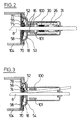
- the sections of FIGS. 2 and 3 show that the pull lever 13 consists of two legs 100 and 101 which are connected by the axes 14 and 15 (FIG. 5).
- the projection 27 on the carriage 26 has a bore 32.
- the tension lever parts 100 and 101 are each provided with a long bore 28.
- a flattened on both sides runs through the bores 28 and the bore 32
- Bolt 103 the component of movement of which is received transversely to the direction of advance of the slide 26 through the long bores 28, and which is rotatable in the bore 32.
- the spring 29 causes the entire feed device to be returned to the illustrated starting position when the trigger 3 is released.
- the carriage guide can be designed as shown in FIG. 6.
- Devices 111 in which inserts 112 are inserted, are present in the housing 21 of the discharge device.
- Corresponding devices 113 of the slide 26 slide in the inserts 112.
- the devices 111 with the inserts 112 and the devices 113 form a tongue and groove sliding system.
- the inserts 112 serve to increase the service life and improve the mechanical properties, such as reduced friction and more precise guidance.
- the clamping levers 30 and 31 are held in the slide 26. As particularly shown in FIG. 5, these each have a bore 43, 44 through which a feed rod 8 passes.
- the bore 43 or 44 is partially towards the front, ie towards the cartridge 4, with a larger cross section.
- the compression spring 34 or 39 is inserted, which is supported and guided by the bore wall in the carriage 26.
- the compression springs 35 and 38 are inserted in a second bore, which press the clamping lever against the opposite pins 41 and 42 with a cambered surface and are also supported on the carriage 26 to the front.
- the bore 43 and 44 may be lined with a material in the area where the feed rod 8 is clamped, for. B. in the form of a socket, which guarantees a long life with good clamping effect.
- release pins 46 and 47 are slidably guided in the feed direction and interact with the release slide 48 resting on the back of the hand-held device.
- the release rod 50 which can be pivoted laterally around the shaft 52 according to FIG. 3, runs under the release slide 48.
- the locking lever 53, 54 In the front part of the housing 21 are in the space between the support plate 18, which is connected to the cartridge holder 104, and the cover plate 58, the locking lever 53, 54. They are set by the springs 74, 75 against the feed rods 8 running through holes in them . Tongues 55, 56 of the locking levers 53, 54 extend into recesses in the shaft 52.
- the feed rods 8 are connected at the rear end by a bridge 17.
- the bridge 17 serves on the one hand from a safety point of view to terminate the feed rods 8 to the rear, prevents a permanent displacement of the feed rods 8 against one another and serves, e.g. when changing the cartridge 4, as a handle for pulling back the feed rods 8.
- the slide 26 is also pulled forward.
- the pins 41 and 42 press eccentrically to the bore 43 and 44 from the rear against the clamping levers 30 and 31. Since in the idle state these always rest against the pins 41 and 42 on the one hand because of the springs 35 and 38, on the other hand the springs 34 and 39 are slightly pretensioned with regard to the clamping of the feed rods 8, a clamp connection between the slide 26 and feed rods 8 is hereby built up without play and evenly by both clamping levers 30 and 31 during the feed.
- the clamping levers 30, 31 move around the Edges 105 and 106, respectively.
- the further forward movement of the slide 26 is then converted into an equal forward movement of the feed rods 8, the tappet plates 7 and finally the squeeze-out piston 110 in the cartridge cylinders 5 and 6, respectively.
- the uniformity of the clamping, and thus ultimately the same advance of the squeezing pistons, is particularly important in multi-component discharge systems for maintaining a constant mixing ratio.
- the construction according to the invention also compensates for different manufacturing play and signs of wear in the clamping elements.
- the trigger 3 is released and the entire feed device automatically returns to the rest position under the action of the spring 29. Since the clamping is released by the clamping levers 30 and 31 during the return movement of the slide 26, the feed rods 8 are not necessarily taken along by this return.
- the clamping levers 30, 31 lie against the wall 108 or 109 of the slide 26 lying in front of them, thereby preventing jamming during the backward movement of the push rods 8.
- the residual friction that still exists between the clamping levers 30, 31 and the feed rods 8 when the carriage 26 runs backward can, in connection with a residual pressure of the cartridge content, lead to a backward entrainment of the feed rods 8.
- a friction brake 65 which is known per se, e.g. B. from the European patent application EP-A-0,408,494 of the applicant, consisting of a slide with a certain friction on one of the feed rods 8 slider 65, the movement of which is limited by a stop 66 relative to the housing 21. Because of a small free path length corresponding to a short retraction of the feed rods 8, running can occur of discharge mass can be prevented.
- the friction brake as shown, only needs to be present on one side, since the stability of the bridge 17 is sufficient to distribute the braking force over both feed rods 8.
- This task is performed by the locking levers 53 and 54, which are shown in another view in FIGS. 2 and 3.
- the locking levers 53 and 54 are pressed backward by the pressure springs 74 and 75, respectively, by rotation about the edge 70.
- any play of the feed rods 8 in the bores of the locking levers 53, 54 is thereby rendered ineffective, and thus both feed rods are locked as precisely as possible at the same time.
- the smallest backward movement of the feed rods 8 then immediately causes the locking levers 53, 54 to jam due to the offset retaining force of the edge 70, which results in a further Backward movement of the feed rods 8 is safely avoided.
- the release rod 50 is pivoted out of the position shown in FIG. 3.
- the slider 48 is moved upwards by sliding the bevel 49 (see FIG. 4) over the release rod 50, as a result of which the pins 46 and 47 (see FIG. 5) are pushed forward over the bevels 107 of the slider 48 and so that the clamping levers 30 and 31 press into the freewheel position. Since the locking levers 53, 54 still absorb the backward pressure, only little force is required for this.
- both of the two backstops specified in the exemplary embodiment may be present or one may be omitted, ie only the friction brake or only the locking lever brake can be present.
- the friction brake could also be used several times, especially for everyone Feed rods are available. It could then consist of several friction bodies or a single larger one, which grips the feed rods.
- the friction brake could also be attached to the housing of the discharge device without play in order to prevent any free return.
- a further position of the release rod could be provided, in which the locking levers 53, 54 are pressed into the freewheel position, but the clamping levers 30, 31 are released, i. H. the slider 48 is not pushed up. In this position, only the friction backstop is effective, as a result of which the discharge device can be quickly switched from the discharge of highly viscous to the discharge of low-viscosity masses.
- locking devices such as Clamping screws that push the locking levers 53, 54 into the freewheel position.
- the exemplary embodiment according to FIG. 7 has some simplifications.
- the handle 2 with the trigger 3 and the double cartridge with the two cylinders 5 and 6 are the same as in the previous example. The same applies to the other components 7-11.
- the pull tab 11 acts via the bearing pin 120 on the pull lever 121, which is rotatably held in the housing via a fixed axis of rotation 122 and is connected to the slide 125 via a bolt 124 sliding in the elongated hole 123.
- a second bore is provided in the housing in order to achieve the gear ratio to be able to change.
- the slide guide is designed similar to that illustrated in FIG. 6.
- the two clamping levers 126 and 127 are arranged in the carriage 125 at the same height, but obliquely with respect to the plane of the push rod, that is, the clamping lever 126 points to the rear in the arrangement of FIG.
- the actuation and action of the clamping levers via pins 41 with a convex surface and the bore 43 with compression spring 34 is the same as in the previous examples, but tension springs 128 fastened to the slide act on the ends of the clamping levers on the push rod side instead of compression springs 35.
- the friction brake 129 is similar in effect and structure to the friction brake 65.
- the exemplary embodiment according to FIG. 7 has above all a more effective unlocking of the backstop containing the locking levers 53 and 54 and the clamping lever.
- This unlocking mechanism which is effective for changing the cartridge or relieving the cartridge against reflowing, contains a first unlocking rocker 130 acting on the clamping levers and a second unlocking rocker 132 acting on the locking levers.
- the first rocker is connected to the second rocker approximately in the middle via a guided rod 133.
- An unlocking lever 134 which is mounted about axis 135 and has a high transmission ratio, engages on the first rocker 130.
- a return spring 136 is connected to the release lever.
- the first rocker 130 has two adjustable threaded bolts 137 which, when the unlocking lever 134 is actuated, act on pressure pins 131 in the slide, and these in turn act on the clamping levers in order to bring them straight, ie into the inactive position.
- the second rocker 132 has a compression spring 138 which is supported on the housing.
- the first rocker 130 acts on the one hand via the threaded bolts 137 on the pressure pins 131 in the slide and these on the outer ends of the clamping levers, and on the other hand directly via the rod 133 on the second rocker 132, which acts on the locking levers, thereby both the Clamping levers as well as the locking levers can be unlocked to enable the push rods to be pulled freely or the cartridges to be relieved.
- the bridge 139 is produced from two shaped pieces which grasp the push rods 8 axially without any play and radially with some play and are screwed together.
- Conventional lightweight materials preferably plastics or light metals, can be used as the material for the housing of the discharge device and for almost all internal parts.
- the more heavily loaded parts such as the lever 13 and its mounting in the housing, the pins 41 and 42 etc. can be made of metal, for example.
- the bearings and also the through bores in the clamping and locking levers 30, 31 or 53, 54 and the slide 26 can be equipped with metal bushings, the feed rods, in order to avoid indentations, to be made of correspondingly hard or surface-hardened material.
- the inside of the guides and the surface of the feed rods can be smoothed or polished to allow the rods to slide easily in the guides. The large clamping forces still ensure sufficient driving force.
Landscapes
- Engineering & Computer Science (AREA)
- Mechanical Engineering (AREA)
- Coating Apparatus (AREA)
- Feeding, Discharge, Calcimining, Fusing, And Gas-Generation Devices (AREA)
- Containers And Packaging Bodies Having A Special Means To Remove Contents (AREA)
Applications Claiming Priority (2)
| Application Number | Priority Date | Filing Date | Title |
|---|---|---|---|
| CH758/92 | 1992-03-10 | ||
| CH275892 | 1992-09-02 |
Publications (2)
| Publication Number | Publication Date |
|---|---|
| EP0586342A1 true EP0586342A1 (fr) | 1994-03-09 |
| EP0586342B1 EP0586342B1 (fr) | 1996-12-27 |
Family
ID=4240956
Family Applications (1)
| Application Number | Title | Priority Date | Filing Date |
|---|---|---|---|
| EP93810592A Expired - Lifetime EP0586342B1 (fr) | 1992-09-02 | 1993-08-23 | Procédé d'avancement de plusieurs tiges, en particulier pour distributeurs manuels |
Country Status (4)
| Country | Link |
|---|---|
| US (1) | US5392956A (fr) |
| EP (1) | EP0586342B1 (fr) |
| JP (1) | JP3591852B2 (fr) |
| DE (1) | DE59304874D1 (fr) |
Cited By (2)
| Publication number | Priority date | Publication date | Assignee | Title |
|---|---|---|---|---|
| US5477987A (en) * | 1993-01-15 | 1995-12-26 | Keller; Wilhelm A. | Dispensing appliance for at least two components |
| US5546996A (en) * | 1994-08-09 | 1996-08-20 | Minnesota Mining And Manufacturing Company | Dispensing cartridge refillng system |
Families Citing this family (7)
| Publication number | Priority date | Publication date | Assignee | Title |
|---|---|---|---|---|
| WO1997026086A2 (fr) * | 1996-01-19 | 1997-07-24 | S.C. Johnson & Son, Inc. | Systeme de dosage variable a deux pistons |
| CN2598664Y (zh) * | 2003-03-11 | 2004-01-14 | 李�杰 | 打胶枪的进给装置 |
| US6938799B1 (en) * | 2003-08-11 | 2005-09-06 | Kenneth R. Berntsen | Sealant/adhesive gun |
| US20050103809A1 (en) * | 2003-11-13 | 2005-05-19 | Mixpac Systems Ag | Electrically operated cartridge dispensing appliance |
| CA2741062C (fr) * | 2011-05-20 | 2013-11-26 | Jdi Design Inc. | Systeme de distribution de substances fluentes a dispositif de mesure de portions ergonomiques |
| DE102012201295A1 (de) * | 2012-01-31 | 2013-08-01 | Hilti Aktiengesellschaft | Auspressgerät |
| EP3251755A1 (fr) | 2016-05-31 | 2017-12-06 | Sulzer Mixpac AG | Distributeur à deux composants |
Citations (1)
| Publication number | Priority date | Publication date | Assignee | Title |
|---|---|---|---|---|
| DE3128611A1 (de) * | 1981-07-20 | 1983-01-27 | Hilti AG, 9494 Schaan | Dosiergeraet fuer mehrkomponenten-massen |
Family Cites Families (10)
| Publication number | Priority date | Publication date | Assignee | Title |
|---|---|---|---|---|
| GB1011470A (en) * | 1963-11-06 | 1965-12-01 | Expandite Ltd | Improvements relating to guns for applying viscous materials such as mastics |
| US3311265A (en) * | 1965-06-03 | 1967-03-28 | Chem Dev Corp | Double-barreled dispensing gun |
| DE3234250A1 (de) * | 1982-09-15 | 1984-03-15 | Hilti AG, 9494 Schaan | Handgeraet zum abgeben von mehrkomponenten-massen |
| US4655372A (en) * | 1984-09-21 | 1987-04-07 | The Joy Of Painting | Paint dispenser |
| DE3873628D1 (de) * | 1987-06-10 | 1992-09-17 | Wilhelm A Keller | Doppel-austragkartusche fuer zweikomponentenmassen. |
| EP0408494B1 (fr) * | 1989-07-13 | 1994-02-09 | Wilhelm A. Keller | Dispositif pour éjection manuelle pour une cartouche double par mélange à deux composants |
| EP0463990B1 (fr) * | 1990-06-22 | 1994-07-20 | Wilhelm A. Keller | Appareil de distribution entraîné électriquement |
| US5137181A (en) * | 1990-07-18 | 1992-08-11 | Wilhelm A. Keller | Manually operated appliance, in particular for a double dispensing cartridge for two-component substances |
| US5197635A (en) * | 1990-11-16 | 1993-03-30 | Chang Peter J Y | Variable thrust caulk dispensing device |
| US5263614A (en) * | 1992-05-14 | 1993-11-23 | Jacobsen Kenneth H | Material dispensing tool for tubular cartridges |
-
1993
- 1993-08-23 EP EP93810592A patent/EP0586342B1/fr not_active Expired - Lifetime
- 1993-08-23 DE DE59304874T patent/DE59304874D1/de not_active Expired - Lifetime
- 1993-09-02 US US08/114,903 patent/US5392956A/en not_active Expired - Lifetime
- 1993-09-02 JP JP21887993A patent/JP3591852B2/ja not_active Expired - Lifetime
Patent Citations (1)
| Publication number | Priority date | Publication date | Assignee | Title |
|---|---|---|---|---|
| DE3128611A1 (de) * | 1981-07-20 | 1983-01-27 | Hilti AG, 9494 Schaan | Dosiergeraet fuer mehrkomponenten-massen |
Cited By (2)
| Publication number | Priority date | Publication date | Assignee | Title |
|---|---|---|---|---|
| US5477987A (en) * | 1993-01-15 | 1995-12-26 | Keller; Wilhelm A. | Dispensing appliance for at least two components |
| US5546996A (en) * | 1994-08-09 | 1996-08-20 | Minnesota Mining And Manufacturing Company | Dispensing cartridge refillng system |
Also Published As
| Publication number | Publication date |
|---|---|
| JPH07797A (ja) | 1995-01-06 |
| US5392956A (en) | 1995-02-28 |
| EP0586342B1 (fr) | 1996-12-27 |
| JP3591852B2 (ja) | 2004-11-24 |
| DE59304874D1 (de) | 1997-02-06 |
Similar Documents
| Publication | Publication Date | Title |
|---|---|---|
| DE3128611C2 (de) | Dosiergerät für Mehrkomponenten-Massen | |
| EP0589828B1 (fr) | Mécanisme d'avancement d'un appareil d'extrusion | |
| DE3234250C2 (fr) | ||
| DE2546696C3 (de) | Medizinisches Klammerinstrument zum Verschließen von schlauchförmigen organischen Gebilden, wie Blutgefäßen | |
| EP0615787B1 (fr) | Distributeur manuel pour cartouche double | |
| EP0507147A1 (fr) | Accouplement | |
| EP0956908A1 (fr) | Extrudeur électrique pour cartouches | |
| EP0463990A1 (fr) | Appareil de distribution entraîné électriquement | |
| EP0791404A1 (fr) | Dispositif manuel de décharge pour une cartouche double | |
| EP0586342B1 (fr) | Procédé d'avancement de plusieurs tiges, en particulier pour distributeurs manuels | |
| DE10020591B4 (de) | Ausgabevorrichtung für viskoses Dentalmaterial | |
| DE1515360B2 (de) | Preßwerkzeug zum Andrucken elektn scher Verbindungsklemmen | |
| EP0408494B1 (fr) | Dispositif pour éjection manuelle pour une cartouche double par mélange à deux composants | |
| DE1627730A1 (de) | Vorrichtung fuer den Zusammenbau von Muttern und Unterlegscheiben od.dgl. mit Schraubenbolzen od.dgl. | |
| EP1101538A2 (fr) | Appareil d'extrusion électrique pour cartouches | |
| DE3610060A1 (de) | Spannvorrichtung | |
| EP0621083A1 (fr) | Dispositif pour vider des cartouches | |
| EP1633418A1 (fr) | Dispositif d'entrainement et procede permettant de faire avancer un element de deplacement en avant | |
| EP0736333A2 (fr) | Dispositif manuel d'extrusion de produit pâteux | |
| EP0274746B1 (fr) | Etrier de tension avec mâchoire de serrage réglable | |
| DE2659768A1 (de) | Zuspannvorrichtung fuer reibungsbremsen, insbesondere von schienenfahrzeugen | |
| DE3941752A1 (de) | Drehmomentvorrichtung | |
| DE3306524A1 (de) | Dosiervorrichtung | |
| DE3112809C2 (fr) | ||
| DE4223230C1 (de) | Klemmeinrichtung für eine Druckplatte |
Legal Events
| Date | Code | Title | Description |
|---|---|---|---|
| PUAI | Public reference made under article 153(3) epc to a published international application that has entered the european phase |
Free format text: ORIGINAL CODE: 0009012 |
|
| AK | Designated contracting states |
Kind code of ref document: A1 Designated state(s): CH DE FR GB IT LI |
|
| 17P | Request for examination filed |
Effective date: 19940822 |
|
| GRAG | Despatch of communication of intention to grant |
Free format text: ORIGINAL CODE: EPIDOS AGRA |
|
| GRAH | Despatch of communication of intention to grant a patent |
Free format text: ORIGINAL CODE: EPIDOS IGRA |
|
| 17Q | First examination report despatched |
Effective date: 19960529 |
|
| GRAH | Despatch of communication of intention to grant a patent |
Free format text: ORIGINAL CODE: EPIDOS IGRA |
|
| GRAA | (expected) grant |
Free format text: ORIGINAL CODE: 0009210 |
|
| ITF | It: translation for a ep patent filed |
Owner name: BARZANO' E ZANARDO MILANO S.P.A. |
|
| AK | Designated contracting states |
Kind code of ref document: B1 Designated state(s): CH DE FR GB IT LI |
|
| REG | Reference to a national code |
Ref country code: CH Ref legal event code: NV Representative=s name: AMMANN PATENTANWAELTE AG BERN |
|
| REF | Corresponds to: |
Ref document number: 59304874 Country of ref document: DE Date of ref document: 19970206 |
|
| GBT | Gb: translation of ep patent filed (gb section 77(6)(a)/1977) |
Effective date: 19970303 |
|
| ET | Fr: translation filed | ||
| PLBE | No opposition filed within time limit |
Free format text: ORIGINAL CODE: 0009261 |
|
| STAA | Information on the status of an ep patent application or granted ep patent |
Free format text: STATUS: NO OPPOSITION FILED WITHIN TIME LIMIT |
|
| 26N | No opposition filed | ||
| REG | Reference to a national code |
Ref country code: GB Ref legal event code: IF02 |
|
| REG | Reference to a national code |
Ref country code: GB Ref legal event code: 732E |
|
| REG | Reference to a national code |
Ref country code: FR Ref legal event code: TP |
|
| REG | Reference to a national code |
Ref country code: CH Ref legal event code: PUE Owner name: MIXPAC SYSTEMS AG Free format text: KELLER, WILHELM A.#OBSTGARTENWEG 9#CH-6402 MERLISCHACHEN (CH) -TRANSFER TO- MIXPAC SYSTEMS AG#GRUNDSTRASSE 12#6343 ROTKREUZ (CH) |
|
| PGFP | Annual fee paid to national office [announced via postgrant information from national office to epo] |
Ref country code: CH Payment date: 20110824 Year of fee payment: 19 |
|
| PGFP | Annual fee paid to national office [announced via postgrant information from national office to epo] |
Ref country code: GB Payment date: 20120821 Year of fee payment: 20 |
|
| PGFP | Annual fee paid to national office [announced via postgrant information from national office to epo] |
Ref country code: FR Payment date: 20120906 Year of fee payment: 20 Ref country code: IT Payment date: 20120822 Year of fee payment: 20 Ref country code: DE Payment date: 20120822 Year of fee payment: 20 |
|
| REG | Reference to a national code |
Ref country code: DE Ref legal event code: R071 Ref document number: 59304874 Country of ref document: DE |
|
| REG | Reference to a national code |
Ref country code: CH Ref legal event code: PL |
|
| REG | Reference to a national code |
Ref country code: GB Ref legal event code: PE20 Expiry date: 20130822 |
|
| PG25 | Lapsed in a contracting state [announced via postgrant information from national office to epo] |
Ref country code: DE Free format text: LAPSE BECAUSE OF EXPIRATION OF PROTECTION Effective date: 20130824 |
|
| PG25 | Lapsed in a contracting state [announced via postgrant information from national office to epo] |
Ref country code: GB Free format text: LAPSE BECAUSE OF EXPIRATION OF PROTECTION Effective date: 20130822 |