EP0585577B1 - Abgasanlage für eine Brennkraftmaschine eines Fahrzeugs mit einem Katalysator - Google Patents
Abgasanlage für eine Brennkraftmaschine eines Fahrzeugs mit einem Katalysator Download PDFInfo
- Publication number
- EP0585577B1 EP0585577B1 EP93111352A EP93111352A EP0585577B1 EP 0585577 B1 EP0585577 B1 EP 0585577B1 EP 93111352 A EP93111352 A EP 93111352A EP 93111352 A EP93111352 A EP 93111352A EP 0585577 B1 EP0585577 B1 EP 0585577B1
- Authority
- EP
- European Patent Office
- Prior art keywords
- piston
- fuel
- housing
- exhaust system
- guide housing
- Prior art date
- Legal status (The legal status is an assumption and is not a legal conclusion. Google has not performed a legal analysis and makes no representation as to the accuracy of the status listed.)
- Expired - Lifetime
Links
Images

Classifications
-
- F—MECHANICAL ENGINEERING; LIGHTING; HEATING; WEAPONS; BLASTING
- F01—MACHINES OR ENGINES IN GENERAL; ENGINE PLANTS IN GENERAL; STEAM ENGINES
- F01N—GAS-FLOW SILENCERS OR EXHAUST APPARATUS FOR MACHINES OR ENGINES IN GENERAL; GAS-FLOW SILENCERS OR EXHAUST APPARATUS FOR INTERNAL COMBUSTION ENGINES
- F01N3/00—Exhaust or silencing apparatus having means for purifying, rendering innocuous, or otherwise treating exhaust
- F01N3/08—Exhaust or silencing apparatus having means for purifying, rendering innocuous, or otherwise treating exhaust for rendering innocuous
- F01N3/10—Exhaust or silencing apparatus having means for purifying, rendering innocuous, or otherwise treating exhaust for rendering innocuous by thermal or catalytic conversion of noxious components of exhaust
- F01N3/24—Exhaust or silencing apparatus having means for purifying, rendering innocuous, or otherwise treating exhaust for rendering innocuous by thermal or catalytic conversion of noxious components of exhaust characterised by constructional aspects of converting apparatus
- F01N3/36—Arrangements for supply of additional fuel
-
- F—MECHANICAL ENGINEERING; LIGHTING; HEATING; WEAPONS; BLASTING
- F01—MACHINES OR ENGINES IN GENERAL; ENGINE PLANTS IN GENERAL; STEAM ENGINES
- F01N—GAS-FLOW SILENCERS OR EXHAUST APPARATUS FOR MACHINES OR ENGINES IN GENERAL; GAS-FLOW SILENCERS OR EXHAUST APPARATUS FOR INTERNAL COMBUSTION ENGINES
- F01N3/00—Exhaust or silencing apparatus having means for purifying, rendering innocuous, or otherwise treating exhaust
- F01N3/08—Exhaust or silencing apparatus having means for purifying, rendering innocuous, or otherwise treating exhaust for rendering innocuous
- F01N3/10—Exhaust or silencing apparatus having means for purifying, rendering innocuous, or otherwise treating exhaust for rendering innocuous by thermal or catalytic conversion of noxious components of exhaust
- F01N3/18—Exhaust or silencing apparatus having means for purifying, rendering innocuous, or otherwise treating exhaust for rendering innocuous by thermal or catalytic conversion of noxious components of exhaust characterised by methods of operation; Control
- F01N3/20—Exhaust or silencing apparatus having means for purifying, rendering innocuous, or otherwise treating exhaust for rendering innocuous by thermal or catalytic conversion of noxious components of exhaust characterised by methods of operation; Control specially adapted for catalytic conversion ; Methods of operation or control of catalytic converters
- F01N3/2006—Periodically heating or cooling catalytic reactors, e.g. at cold starting or overheating
- F01N3/2033—Periodically heating or cooling catalytic reactors, e.g. at cold starting or overheating using a fuel burner or introducing fuel into exhaust duct
-
- F—MECHANICAL ENGINEERING; LIGHTING; HEATING; WEAPONS; BLASTING
- F01—MACHINES OR ENGINES IN GENERAL; ENGINE PLANTS IN GENERAL; STEAM ENGINES
- F01N—GAS-FLOW SILENCERS OR EXHAUST APPARATUS FOR MACHINES OR ENGINES IN GENERAL; GAS-FLOW SILENCERS OR EXHAUST APPARATUS FOR INTERNAL COMBUSTION ENGINES
- F01N2610/00—Adding substances to exhaust gases
- F01N2610/14—Arrangements for the supply of substances, e.g. conduits
-
- Y—GENERAL TAGGING OF NEW TECHNOLOGICAL DEVELOPMENTS; GENERAL TAGGING OF CROSS-SECTIONAL TECHNOLOGIES SPANNING OVER SEVERAL SECTIONS OF THE IPC; TECHNICAL SUBJECTS COVERED BY FORMER USPC CROSS-REFERENCE ART COLLECTIONS [XRACs] AND DIGESTS
- Y02—TECHNOLOGIES OR APPLICATIONS FOR MITIGATION OR ADAPTATION AGAINST CLIMATE CHANGE
- Y02A—TECHNOLOGIES FOR ADAPTATION TO CLIMATE CHANGE
- Y02A50/00—TECHNOLOGIES FOR ADAPTATION TO CLIMATE CHANGE in human health protection, e.g. against extreme weather
- Y02A50/20—Air quality improvement or preservation, e.g. vehicle emission control or emission reduction by using catalytic converters
-
- Y—GENERAL TAGGING OF NEW TECHNOLOGICAL DEVELOPMENTS; GENERAL TAGGING OF CROSS-SECTIONAL TECHNOLOGIES SPANNING OVER SEVERAL SECTIONS OF THE IPC; TECHNICAL SUBJECTS COVERED BY FORMER USPC CROSS-REFERENCE ART COLLECTIONS [XRACs] AND DIGESTS
- Y02—TECHNOLOGIES OR APPLICATIONS FOR MITIGATION OR ADAPTATION AGAINST CLIMATE CHANGE
- Y02T—CLIMATE CHANGE MITIGATION TECHNOLOGIES RELATED TO TRANSPORTATION
- Y02T10/00—Road transport of goods or passengers
- Y02T10/10—Internal combustion engine [ICE] based vehicles
- Y02T10/12—Improving ICE efficiencies
Definitions
- the invention relates to an exhaust system of the type mentioned in the preamble of claim 1 and resulting from DE-OS 41 34 449.
- a burner known from this publication serves to bring the catalytic converter up to its operating temperature more quickly and essentially consists of a combustion chamber and a jacket housing surrounding it via an annular space, into which air is pressed via an air supply line. Furthermore, the fuel is fed into the combustion chamber via a fuel line and is sucked up by a fiberglass mat in this and finally burned by an electrical ignition device provided on the burner.
- such a burner can be operated with any combustible liquid, but usually the fuel present in the vehicle is used for this purpose, which is introduced into the combustion chamber at about 3 to 4 bar via the pump which is also present. Since this pressure is relatively low, combustion in the combustion chamber is relatively poor.
- the object of the invention is therefore to provide a device in an exhaust system of the type mentioned in the preamble of claim 1 without an additional pump specifically assigned to the burner, through which the fuel is supplied to the burner at a pressure which ensures optimum atomization and combustion .
- the pressure of the fuel which is usually around 3 bar, can be increased considerably, namely to about 10 bar, without an additional pump.
- a power amplifier is much cheaper, lighter and more robust in operation, and considerably less noisy than a correspondingly powerful electric pump assigned to the burner (features of claims 1 and 2).
- the power amplifier expediently consists of a stepped piston, the large and small pistons of which can each be moved longitudinally in a housing.
- the housing surrounding the small piston is connected to the burner so that the fuel is introduced into it at the desired high pressure of approximately 10 bar (features of patent claim 3).
- the large piston of the stepped piston is provided so as to be longitudinally displaceable in a hollow cylindrical receiving housing, a guide housing for receiving the small piston being arranged at an end region via an annular flange. Furthermore, an embodiment of the invention is that of the housing housing containing the large piston the guide housing protrudes axially in the region of an end wall, the small piston also being arranged to be longitudinally displaceable therein.
- the stepped piston is penetrated by a central through-bore, which at the free end of the small piston passes into a check valve that opens towards the guide housing (when the stepped piston moves back).
- This advantageously consists of a spring-loaded ball or the like closure element.
- the receiving housing is expediently arranged within a fuel tank, the pressure chamber of the large piston being connected to a fuel line fed by the fuel pump via a fuel line.
- the receiving housing, the guide housing and / or the stepped piston can be made of metal, plastic or ceramic (features of claim 8).
- An exhaust gas catalytic converter is usually only preheated by the burner for about a minute after a cold start; because the operating temperature of the exhaust gas catalytic converter is then maintained by the exhaust gas flow. However, if the engine is switched off shortly after a cold start If the fuel is to be fed to the burner again for repeated - or possibly repeated (i.e. at intervals) - preheating of the exhaust gas catalytic converter.
- a flow valve is provided in the large piston of the stepped piston or an axially displaceable control ring with at least one lateral passage opening is provided in the high-pressure chamber of the guide housing.
- the stepped piston is pushed out again immediately after its insertion by pressurizing the inside end face of the large piston and by spring action, so that a fuel can again flow into the high-pressure chamber of the guide housing. This process can be repeated as often as required, depending on the design and design of the booster.
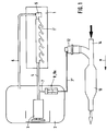
- the system shown in Fig. 1 for supplying the internal combustion engine 1 of a passenger car with fuel has a fuel tank 2 with an electrically operated fuel pump 3, from which the fuel via a feed line 4 with a system pressure of about 3 bar into the injection bar 1 'of the internal combustion engine 1 is funded.
- a pressure regulator 5 is provided at the end region of the injection bar 1 ′, with which a return line 6 is connected, which in turn opens into the fuel tank 2.
- a first fuel line 7 branches off from the supply line 4 and is connected to a hollow cylindrical receptacle housing 8 arranged inside the fuel tank 2.
- the fuel (fuel) flowing from the supply line 4 via the fuel lines 7 and 7 ′ and the receiving housing 8 into the burner 12 is provided by a burner 12 when the internal combustion engine 1 is started , electric igniter burned and thereby the catalytic converter 13 for a period preheated for about a minute.
- the operating temperature of the exhaust gas catalytic converter 13 is then maintained by the exhaust gas flow of the exhaust gas line 14.
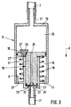
- the large piston 16 of a stepped piston 15 is arranged to be longitudinally displaceable in the hollow cylindrical receiving housing 8, a small piston 17 projecting axially from the large piston 16. This in turn is arranged to be longitudinally displaceable in the guide housing 9.
- a compression spring 18 is supported on the ring flange 11 and acts with a prestress against the opposite end face of the large piston 16. This is displaced by the action of the compression spring 18 close to the end wall 19 of the receiving housing 8 provided with the first fuel line 7 via a connecting piece 31.
- a connecting piece 32 projects from the end wall of the guide housing 9, to which the second fuel line 7 'is attached.
- the stepped piston 15 is penetrated by a central through bore 20, which opens out at the free end of the small piston 17 into a check valve opening towards the high pressure chamber 21 of the guide housing 9.
- the check valve has a ball 22 which, in the rest position, is pressed by a leaf spring 23 attached to the end face of the small piston 17 against the bottom of a recess 24 which is formed at the free end region of the small piston 17 and into which the through hole 20 opens .
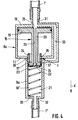
- the receptacle housing 8 a shown in FIGS. 4 and 5 is largely identical in construction to the receptacle housing 8 explained in FIGS. 2 and 3. The same components are therefore provided with the same reference numerals.
- the small piston 17 of the stepped piston 15 is, however, formed on a holding projection 29 which projects centrally from the large piston 16 and which has a substantially smaller diameter than the small piston 17.
- the hollow cylindrical guide housing 9 a protrudes axially outward, the compression spring 18 'being supported on the end wall 30 of the guide housing 9 a facing the burner 12, which acts with prestress against the small piston 17.
- a connecting piece 32 for the second fuel line 7 ' is provided on the end wall 30.
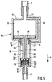
- a flow channel 33 is formed on the receiving housing 8 a, which branches off from the region of the opening of the connecting piece 31 of the first fuel line 7 into the pressure chamber 25, runs along a side wall of the receiving housing 8 a and finally opens into the high-pressure chamber 21 of the guide housing 9 a ( in the open position b of the control ring 34). Furthermore, in the mouth area of the flow channel 33 there is a control ring 34 surrounding the holding extension 29 of the stepped piston 15 with a large radial distance and having a radially extending through opening 35.
- the control ring 34 is axially displaceable over its circumferential wall along the wall of the high pressure chamber 21 of the guide housing 9 a between an open position b (FIG. 5) and a closed position c (FIG. 4).
- a guide lug 36 projects radially from the control ring 34 and engages in an associated, longitudinal recess of the guide housing 9 a.
- the large piston 16 of the stepped piston 15 is displaced by the action of the compression spring 18 'up to the end wall 19 of the receiving housing 8 a and thereby also the control ring 34 is shifted into its closed position c , in which it covers the mouth of the flow channel 33 in the high pressure chamber 21 of the guide housing 9 a sealing (Fig. 4).
- the receiving housing 8 and 8 a provided with the stepped piston 15 and guide housing 9 and 9 a forms a power amplifier, the fuel flowing into the receiving housing 8 and 8 a at about 3 bar being increased to about 10 bar for introduction into the burner 12.
- the large piston 16 can for example have a diameter of approximately 50 mm, while the small piston 17 can have a diameter of approximately 20 mm, for example.
- the receiving housing 8 and 8 a and the stepped piston 15 can be made entirely or partially, as well as the respective individual parts made of plastic, metal or ceramic.
- the housing 8 can also be equipped without the flow valve 27 or the housing 8 a without the control ring 34 be. When the stepped piston 15 is displaced, the fuel can finally flow into the fuel tank 2 via an opening 37 provided on the receiving housing 8 and 8 a.
- the mode of operation of the power amplifier according to the invention is as follows with reference to FIGS. 1 to 5:
- a fuel is fed into the supply line 4 from the fuel tank 2 by the fuel pump 3, the pressure present being regulated by the pressure regulator 5; in the present exemplary embodiment it is approximately 3 bar.
- the fuel (fuel) is also fed into the pressure chamber 25 of the receiving housing 8 via the first fuel line 7 (FIG. 2) and the large piston 16 of the stepped piston 15 is thereby displaced in the direction of arrow d against the action of the compression spring 18 (FIG. 3) .
- the area ratios of the large piston 16 and the small piston 17 are coordinated with one another in such a way that the fuel that flows into the high-pressure chamber 21 when the stepped piston 15 is displaced against the direction of the arrow d through the through bore 20 and with the check valve (ball 22) open - as explained below -
- the stepped piston 15 is moved further in the direction of arrow d to a pressure of about 10 bar; with this pressure, the fuel finally reaches the burner 12 via the second fuel line 7 '.
- a temperature sensor which measures the preheating temperature of the exhaust gas catalytic converter 13 to be reached and switches off the burner 12 when this temperature is reached; After a cold start, the preheating time of the exhaust gas catalytic converter 13 is approximately one minute, depending on the outside temperature.
- the preheating time of the exhaust gas catalytic converter 13 is approximately one minute, depending on the outside temperature.
- the large piston 16 Due to the prevailing flow pressure, the large piston 16 is pressurized on the back, so that it is pushed out by it and by the action of the relaxing compression spring 18 against arrow direction d and finally reaches the end position shown in FIG. 2.
- the flow valve 27 is also closed. During this process, i.e. when the stepped piston 15 is displaced in the direction of the arrow d, the through bore 20 of the stepped piston 15 is flowed through by the fuel and the ball 22 is lifted from the bottom of the recess 24 against the action of the leaf spring 23, so that the fuel flows into the high pressure chamber 21 of the guide housing 9 can flow.
- the stepped piston 15 is again displaced in the direction of arrow d, the ball 22 is pressed against the bottom of the recess 24 by the action of the leaf spring 23 and by the fuel present in the high-pressure chamber 21, ie the check valve is closed.
- fuel can be fed repeatedly into the burner 12 from the high pressure chamber 21 of the receiving housing 8 and the second fuel line 7 '.
- Whose temperature sensor responds when the preheating temperature of the exhaust gas catalytic converter 13 is reached and at the same time closes the fuel supply valve in the burner 12.
- a liquid backflow builds up in the second fuel line 7 ', which causes the stepped piston 15 to remain in its respective sliding position in the receiving housing 8.
- the receiving housing 8 a shown in FIGS. 4 and 5 with stepped piston 15 is largely functionally identical to the receiving housing 8 explained with reference to FIGS. 2 and 3. Therefore, only the functional differences in the operation of the receiving housing 8 a are explained below.
- the stepped piston 15 is displaced in the direction of the arrow d against the action of the compression spring 18', the control ring 34 being in its closed position c and thus in the flow channel 33 inflowing fuel can not drain.
- the high-pressure chamber 21 can be filled with fuel only once after a cold start of the internal combustion engine 1.
Applications Claiming Priority (2)
| Application Number | Priority Date | Filing Date | Title |
|---|---|---|---|
| DE4229595 | 1992-09-04 | ||
| DE4229595A DE4229595C1 (ko) | 1992-09-04 | 1992-09-04 |
Publications (3)
| Publication Number | Publication Date |
|---|---|
| EP0585577A2 EP0585577A2 (de) | 1994-03-09 |
| EP0585577A3 EP0585577A3 (de) | 1994-10-19 |
| EP0585577B1 true EP0585577B1 (de) | 1996-01-10 |
Family
ID=6467253
Family Applications (1)
| Application Number | Title | Priority Date | Filing Date |
|---|---|---|---|
| EP93111352A Expired - Lifetime EP0585577B1 (de) | 1992-09-04 | 1993-07-15 | Abgasanlage für eine Brennkraftmaschine eines Fahrzeugs mit einem Katalysator |
Country Status (3)
| Country | Link |
|---|---|
| US (1) | US5435130A (ko) |
| EP (1) | EP0585577B1 (ko) |
| DE (2) | DE4229595C1 (ko) |
Families Citing this family (9)
| Publication number | Priority date | Publication date | Assignee | Title |
|---|---|---|---|---|
| DE19944388A1 (de) * | 1999-09-16 | 2001-03-22 | Bosch Gmbh Robert | Vorrichtung zum Aufheizen eines Schadstoff-Katalysators |
| DE10123914B4 (de) * | 2001-05-17 | 2005-10-20 | Bosch Gmbh Robert | Kraftstoffeinspritzeinrichtung mit Druckübersetzungseinrichtung und Druckübersetzungseinrichtung |
| US7118352B2 (en) * | 2003-09-17 | 2006-10-10 | Oil-Rite Corporation | Hydraulic metering device |
| US7762060B2 (en) * | 2006-04-28 | 2010-07-27 | Caterpillar Inc. | Exhaust treatment system |
| US7849679B2 (en) * | 2008-12-04 | 2010-12-14 | Caterpillar Inc | Fuel delivery system having multi-output pump |
| US7845336B2 (en) * | 2008-12-18 | 2010-12-07 | Caterpillar Inc | Fuel delivery system having electric pump |
| US20110232270A1 (en) * | 2010-03-23 | 2011-09-29 | Burkitt Joseph S | Fuel system having multi-functional electric pump |
| US10473223B2 (en) | 2017-03-02 | 2019-11-12 | Oil-Rite Corporation | Evacuation valve |
| IT202100020318A1 (it) * | 2021-07-29 | 2023-01-29 | Marelli Europe Spa | Metodo di controllo di un sistema di post-trattamento dei gas di scarico per un impianto di scarico dei gas esausti di un motore a combustione interna |
Family Cites Families (11)
| Publication number | Priority date | Publication date | Assignee | Title |
|---|---|---|---|---|
| US2789510A (en) * | 1954-03-11 | 1957-04-23 | Black Sivalls & Bryson Inc | Liquid injector |
| GB784122A (en) * | 1955-01-12 | 1957-10-02 | British Thomson Houston Co Ltd | Apparatus for generating a flow of gaseous working fluid for a prime mover |
| FR1400585A (fr) * | 1964-04-16 | 1965-05-28 | Gullick Ltd | Appareil multiplicateur de pression et ses applications |
| DE2129023A1 (de) * | 1971-06-11 | 1972-12-28 | Volkswagenwerk Ag, 3180 Wolfsburg | Anordnung zur Abgasreinigung |
| US3761229A (en) * | 1971-07-19 | 1973-09-25 | Ford Motor Co | Engine exhaust gas purification system |
| DE2158119A1 (de) * | 1971-11-24 | 1973-05-30 | Bosch Gmbh Robert | Abgasentgiftungsanlage |
| JPS5440691B2 (ko) * | 1972-05-31 | 1979-12-05 | ||
| CA1321110C (en) * | 1988-11-29 | 1993-08-10 | Philip G. Hill | Intensifier-injector for gaseous fuel for positive displacement engine |
| DE4134449A1 (de) * | 1990-10-23 | 1992-04-30 | Gerd Waschkuttis | Kaltstartbrenner |
| US5211009A (en) * | 1990-12-17 | 1993-05-18 | Kloeckner-Humboldt-Deutz Ag | Method for the regeneration of particulate-filter systems |
| DE4132814C2 (de) * | 1991-10-02 | 1994-02-17 | Pierburg Gmbh | Verfahren und Vorrichtung zur Abgasentgiftung einer Brennkraftmaschine |
-
1992
- 1992-09-04 DE DE4229595A patent/DE4229595C1/de not_active Expired - Fee Related
-
1993
- 1993-07-15 EP EP93111352A patent/EP0585577B1/de not_active Expired - Lifetime
- 1993-07-15 DE DE59301400T patent/DE59301400D1/de not_active Expired - Fee Related
- 1993-09-07 US US08/116,830 patent/US5435130A/en not_active Expired - Fee Related
Also Published As
| Publication number | Publication date |
|---|---|
| EP0585577A3 (de) | 1994-10-19 |
| US5435130A (en) | 1995-07-25 |
| DE59301400D1 (de) | 1996-02-22 |
| EP0585577A2 (de) | 1994-03-09 |
| DE4229595C1 (ko) | 1993-08-19 |
Similar Documents
| Publication | Publication Date | Title |
|---|---|---|
| EP3090164B1 (de) | Dual-fuel-kraftstoffinjektor | |
| EP1636485B1 (de) | Injektor für kraftstoff-einspritzsysteme von brennkraftmaschinen, insbesondere von direkteinspritzenden dieselmotoren | |
| DE102014225167A1 (de) | Kraftstoffzumessventil für eine Brennkraftmaschine und Verfahren zum Betreiben desselben | |
| US4339080A (en) | Fuel injection nozzle | |
| DE19706591A1 (de) | Druckventil | |
| EP0585577B1 (de) | Abgasanlage für eine Brennkraftmaschine eines Fahrzeugs mit einem Katalysator | |
| DE102017201275B4 (de) | Verbrennungskraftmaschine mit kraftstoff-einspritzsüde mit zusätzlicher zuführung eines verbrennungsfördernden mediums in den brennraum | |
| EP2027386B1 (de) | Einspritzinjektor für brennkraftmaschinen | |
| DE102006049885A1 (de) | Injektor zur Einspritzung von Kraftstoff in Brennräume von Brennkraftmaschinen | |
| WO2019233768A1 (de) | Verfahren zum betreiben eines kraftstoffinjektors | |
| DE3150883A1 (de) | "brennstoff-einspritzduese" | |
| DE10229413A1 (de) | Druckübersetzersteuerung durch Bewegung eines Einspritzventilgliedes | |
| EP1682769B1 (de) | Kraftstoffinjektor mit mehrteiligem, direktgesteuertem einspritzventilglied | |
| EP1088985A3 (de) | Injektor für eine Brennkraftmaschine mit Direkteinspritzung | |
| DE19929473B4 (de) | Kraftstoffeinspritzventil | |
| DE10032517A1 (de) | Injektor mit Steuerteilführung | |
| DE19618650B4 (de) | Verfahren zur Herstellung eines Kraftstoffeinspritzventils für Brennkraftmaschinen | |
| DE3928912A1 (de) | Kraftstoffeinspritzduese fuer brennkraftmaschinen | |
| EP1260700A1 (de) | Kraftstoffeinspritzeinrichtung für eine Brennkraftmaschine | |
| DE102018206101A1 (de) | Düsenbaugruppe für einen Kraftstoffinjektor, Kraftstoffinjektor | |
| DE10337893A1 (de) | Brennstoffeinspritzanlage und Verfahren zum Einspritzen von Brennstoff | |
| DE102012022498A1 (de) | Zweistoff-Injektor | |
| DE4426946A1 (de) | Vorrichtung zum Fördern von Kraftstoff aus einem Vorratsbehälter zur Brennkraftmaschine eines Kraftfahrzeugs | |
| EP1260702A2 (de) | Kraftstoffeinspritzeinrichtung für eine Brennkraftmaschine | |
| DE10132450B4 (de) | Kraftstoffeinspritzventil für Brennkraftmaschinen |
Legal Events
| Date | Code | Title | Description |
|---|---|---|---|
| PUAI | Public reference made under article 153(3) epc to a published international application that has entered the european phase |
Free format text: ORIGINAL CODE: 0009012 |
|
| AK | Designated contracting states |
Kind code of ref document: A2 Designated state(s): DE FR GB IT |
|
| PUAL | Search report despatched |
Free format text: ORIGINAL CODE: 0009013 |
|
| AK | Designated contracting states |
Kind code of ref document: A3 Designated state(s): DE FR GB IT |
|
| 17P | Request for examination filed |
Effective date: 19941007 |
|
| 17Q | First examination report despatched |
Effective date: 19950301 |
|
| GRAA | (expected) grant |
Free format text: ORIGINAL CODE: 0009210 |
|
| AK | Designated contracting states |
Kind code of ref document: B1 Designated state(s): DE FR GB IT |
|
| GBT | Gb: translation of ep patent filed (gb section 77(6)(a)/1977) |
Effective date: 19960106 |
|
| REF | Corresponds to: |
Ref document number: 59301400 Country of ref document: DE Date of ref document: 19960222 |
|
| ET | Fr: translation filed | ||
| ITF | It: translation for a ep patent filed |
Owner name: STUDIO JAUMANN |
|
| PLBE | No opposition filed within time limit |
Free format text: ORIGINAL CODE: 0009261 |
|
| STAA | Information on the status of an ep patent application or granted ep patent |
Free format text: STATUS: NO OPPOSITION FILED WITHIN TIME LIMIT |
|
| 26N | No opposition filed | ||
| PGFP | Annual fee paid to national office [announced via postgrant information from national office to epo] |
Ref country code: DE Payment date: 19980701 Year of fee payment: 6 |
|
| PGFP | Annual fee paid to national office [announced via postgrant information from national office to epo] |
Ref country code: GB Payment date: 19990715 Year of fee payment: 7 |
|
| PGFP | Annual fee paid to national office [announced via postgrant information from national office to epo] |
Ref country code: FR Payment date: 19990730 Year of fee payment: 7 |
|
| PG25 | Lapsed in a contracting state [announced via postgrant information from national office to epo] |
Ref country code: DE Free format text: LAPSE BECAUSE OF NON-PAYMENT OF DUE FEES Effective date: 20000503 |
|
| PG25 | Lapsed in a contracting state [announced via postgrant information from national office to epo] |
Ref country code: GB Free format text: LAPSE BECAUSE OF NON-PAYMENT OF DUE FEES Effective date: 20000715 |
|
| GBPC | Gb: european patent ceased through non-payment of renewal fee |
Effective date: 20000715 |
|
| PG25 | Lapsed in a contracting state [announced via postgrant information from national office to epo] |
Ref country code: FR Free format text: LAPSE BECAUSE OF NON-PAYMENT OF DUE FEES Effective date: 20010330 |
|
| REG | Reference to a national code |
Ref country code: FR Ref legal event code: ST |
|
| PG25 | Lapsed in a contracting state [announced via postgrant information from national office to epo] |
Ref country code: IT Free format text: LAPSE BECAUSE OF NON-PAYMENT OF DUE FEES;WARNING: LAPSES OF ITALIAN PATENTS WITH EFFECTIVE DATE BEFORE 2007 MAY HAVE OCCURRED AT ANY TIME BEFORE 2007. THE CORRECT EFFECTIVE DATE MAY BE DIFFERENT FROM THE ONE RECORDED. Effective date: 20050715 |