EP0583064B1 - Récepteur d'appel radio avec unité d'affichage - Google Patents
Récepteur d'appel radio avec unité d'affichage Download PDFInfo
- Publication number
- EP0583064B1 EP0583064B1 EP93305359A EP93305359A EP0583064B1 EP 0583064 B1 EP0583064 B1 EP 0583064B1 EP 93305359 A EP93305359 A EP 93305359A EP 93305359 A EP93305359 A EP 93305359A EP 0583064 B1 EP0583064 B1 EP 0583064B1
- Authority
- EP
- European Patent Office
- Prior art keywords
- message
- memory
- item
- information item
- information
- Prior art date
- Legal status (The legal status is an assumption and is not a legal conclusion. Google has not performed a legal analysis and makes no representation as to the accuracy of the status listed.)
- Expired - Lifetime
Links
- 230000015654 memory Effects 0.000 claims description 83
- 230000008859 change Effects 0.000 claims description 14
- 238000010586 diagram Methods 0.000 description 5
- 230000005540 biological transmission Effects 0.000 description 2
- 239000000872 buffer Substances 0.000 description 1
- 230000006870 function Effects 0.000 description 1
- 239000004973 liquid crystal related substance Substances 0.000 description 1
- 230000004048 modification Effects 0.000 description 1
- 238000012986 modification Methods 0.000 description 1
- 230000003252 repetitive effect Effects 0.000 description 1
- 230000004044 response Effects 0.000 description 1
Images


Classifications
-
- H—ELECTRICITY
- H04—ELECTRIC COMMUNICATION TECHNIQUE
- H04B—TRANSMISSION
- H04B5/00—Near-field transmission systems, e.g. inductive or capacitive transmission systems
-
- G—PHYSICS
- G08—SIGNALLING
- G08B—SIGNALLING OR CALLING SYSTEMS; ORDER TELEGRAPHS; ALARM SYSTEMS
- G08B5/00—Visible signalling systems, e.g. personal calling systems, remote indication of seats occupied
- G08B5/22—Visible signalling systems, e.g. personal calling systems, remote indication of seats occupied using electric transmission; using electromagnetic transmission
- G08B5/222—Personal calling arrangements or devices, i.e. paging systems
- G08B5/223—Personal calling arrangements or devices, i.e. paging systems using wireless transmission
- G08B5/224—Paging receivers with visible signalling details
- G08B5/227—Paging receivers with visible signalling details with call or message storage means
Definitions
- the present invention relates to a radio paging receiver with a display unit and, more particularly, to a radio paging receiver with a display unit which can effectively use a limited memory area.
- a received message is stored in a memory and can be displayed upon reception. In this case, if an identical message is received, the message is not stored in the memory. Otherwise, every time a new message is received, a message display operation as a notifying operation is performed, and the message is stored in the memory.
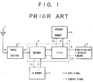
- Fig. 1 is a block diagram showing an arrangement of a conventional radio paging receiver with a display unit.
- a radio signal received through an antenna 1 is amplified and demodulated by a radio section 2 and is input, as a digital signal B, to a decoder 4.
- the decoder 4 collates an address contained in this digital signal, i.e., a paging number, with a self-address C stored in an ID memory 5. If they coincide with each other, a CPU stores a message code D accompanying the address code in a message memory 6, and outputs a control signal (3) for controlling a notification/display means 7 to perform a notification and display a message E.
- Reading of the self-address C from the ID memory 5 is performed by using a control signal (1) from the decoder 4 and reading/writing of the message D from/in the message memory 6 is performed by using a control signal (2) from the CPU. If the received message is stored in the message memory 6, the message D or E stored in the message memory 6 can be displayed by the notification/display means 7 using control signals (2) and (3) from the CPU.
- a control section 3 consists of the decoder 4 and the CPU.
- WO 86/04476 describes a radio pager, a transmission for which includes "label", "address” and “message” signals.
- the pager stores the label and message signals in buffers; if the appropriate address is detected by a comparator the stored label signal is compared with previously received label signals. If the label has yet to be received, the label and message are stored in a label memory and a message memory respectively. If the label has been previously received, the message stored in the message memory may be updated.
- WO86/03318 describes a radio receiver adapted to receive a message, a portion of which comprises an identity code of the message. If an identity code of a newly-received message has already been received and stored by the receiver, the newly-received message will not be stored in the receiver.
- the present invention provides a radio paging receiver with a display unit, the receiver comprising storage/display means and update means, characterised in that said receiver is adapted to receive a signal comprising a paging number corresponding to an information field to be received by the receiver, a specific portion of a message contained in said signal corresponding to an individual information item, in the information field, which is to be received, and a remaining portion of the message corresponding to information associated with the information item, the receiver further comprising input means for selecting an individual information item to be received, the storage/display means being adapted to store and display an individual information item selected by said input means and information associated with the information item, and the update means being adapted to update automatically said storage/display means upon reception of a new message only when the specific portion of the message corresponds to the selected individual information item stored in said storage/display means, and information associated with the information item changes with respect to that stored in said storage/display means.
- a radio paging receiver with a display unit comprises a first memory for storing a specific character and symbol train, a second memory for storing a received message, message collating means for determining whether the specific character and symbol train is contained in the received message, second memory control means for controlling storage of the received message in the second memory on the basis of the determination result obtained by the message collating means.
- the second memory control means erases the first message and causes the second memory to newly store the second message.
- the receiver may further comprise input means for selecting an individual information item to be received, storage/display means for storing and displaying the individual information item selected by the input means and information associated with the information item, and update means for updating the storage/display means upon reception of a new message only when a specific portion of the message corresponds to the selected individual information item, and contents of information associated with the information item change, wherein a paging number corresponds to an information field to be received, a specific portion of a message corresponds to an individual information item, in the information field, which is to be received, and a remaining portion of the message corresponds to information associated with the information item.
- the receiver may further comprise input means for, when the individual information item to be received is selected, further selecting an important individual information item, and notifying means for performing a special notification when contents of information associated with the selected important individual information item change.
- the radio paging receiver with a display unit of the present invention it is checked whether a specific character and symbol train is contained in a received message. If it is determined that a first message containing the specific character and symbol train has already been stored in the second memory, and the specific character and symbol train is also contained in a newly received second message, the first message is erased, and the second message is stored in the second memory. With this operation, when a new message associated with an item defined by a specific character and symbol train, i.e., a specific item, is received, an old message stored in the message memory is erased, and one latest message can be stored.
- an individual information item to be received is selected, and the selected individual information item and information associated therewith are stored and displayed.
- the stored contents are replaced with a newly received message only when a specific portion of the received message corresponds to selected information item, and the contents of information associated with the information item change.
- an important individual information item is further selected. If the- contents of information associated with the selected important individual information item change, a special notification is performed. With this operation, when a large number of messages whose contents change with time with respect to specific items are received, messages indicating the current states of specific contents can be efficiently received.
- the embodiment shown in Fig. 2 comprises an antenna 1, a radio section 2 for demodulating a received input signal a to output a digital signal b as a paging number, a decoder 4 for receiving and decoding the output signal b from the radio section 2, an ID memory 5 for storing a self-address, a first memory 6a for storing both a preset individual information item and information indicating whether the individual information item is selected as a desired reception item by a carrier of the receiver, a first message collating section 8a for collating a message code output from the decoder 4 with the individual information item in the first memory 6a, a CPU 9, a second memory 6b for storing detailed information associated with a selected individual information item sent through a message, and a second message collating section 8b for receiving the information associated with-the selected individual information item from the first message collating section 8a, collating the information with the stored contents of the second memory 6b to check a change in information contents, and sending the resultant data to the CPU 9.
- the embodiment also comprises an LCD driver 10, an LCD 11, a loudspeaker driving section 12, and a loudspeaker 13, which are included in a notification/display means 7, and an item selecting switch 14 for setting an individual information item.
- a control section 3 is constituted by the first and second message collating sections 8a and 8b, the decoder 4, and the CPU 9.
- the item selecting switch 14 and its cooperative components such as the CPU 9, the LCD driver 10, the LCD11, the first memory 6a constitute an input means; the second memory 6b, the CPU 9, the LCD driver 10, and the LCD 11 constitute a storage/display means; the first and second message collating sections 8a and 8b, and the second memory 6b constitute an update means; and the first and second memories 6a and 6b, the first and second message collating sections 8a and 8b, the CPU 9, the LCD driver 10, the LCD 11, the loudspeaker driving section 12, and the loudspeaker 13 also serve as a notification means.
- the radio signal a received by the antenna 1 is amplified and demodulated by the radio section 2 and is input, as the digital signal b , to the decoder 4.
- the decoder 4 collates an address contained in the digital signal b , i.e., the paging number, with a self-address c stored in the ID memory 5. When they coincide with each other, the decoder 4 outputs a message code d accompanying the address code to the first message collating section 8a. In this case, the self-address c is read out from the ID memory 5 under the control (1) of the decoder 4.
- the self-address used in this case corresponds to the field of information sent through a message, e.g., "PARKING-LOT INFORMATION" or "AIRLINE TICKET VACANCY STATE" rather than an address unique to the radio paging receiver with a display unit (to be referred to as the receiver hereinafter).
- the first memory 6a serves to store a character and symbol train transmitted as a specific portion of a message corresponding to an individual information item preset with respect to such an address, which item is, for example, "YOKOHAMA STATION HIGASHIGUCHI DAIICHI” or "YOKOHAMA STATION NISHIGUCHI CHIKA” for "PARKING-LOT INFORMATION".
- the first memory 6a also stores information indicating whether such an individual information item is selected, as an item to be received, by the carrier of the receiver.
- control (2) When the message code d is input to the first message collating section 8a, a selected individual information item e 1 stored in the first memory 6a is referred to (control (2)), and a specific portion of the message is collated with the selected individual item to check whether they correspond to each other. A collation result f 1 is output to the second message collating section 8b.
- Information g transmitted through the message and associated with the selected individual information item e 1 is stored in the second memory 6b.
- the second message collating section 8b Upon reception of the collation result f 1 from the first message collating section 8a, the second message collating section 8b compares the information portion, of the received message, which is associated with the individual information item with the current information g by referring to the second memory 6b (control (3)) so as to check whether the contents of the information have changed.
- the second message collating section 8b outputs the resultant data to the CPU 9.
- the CPU 9 Upon reception of an output f 2 from the second message collating section 8b, which output indicates that new information associated with the individual information item is received, the CPU 9 receives a received message i from the decoder 4 and performs loudspeaker control (4) of the loudspeaker driving section 12 to cause the loudspeaker 13 to generate a notifying sound j . In addition, the CPU 9 performs driver control (4') of the LCD (Liquid Crystal Display) driver 10 to cause the LCD 11 to display a message k , and writes new information h in the second memory 6b to update the corresponding information.
- driver control (4') of the LCD (Liquid Crystal Display) driver 10 to cause the LCD 11 to display a message k , and writes new information h in the second memory 6b to update the corresponding information.
- the information g or h stored in the second memory 6b can be read out by the CPU 9 (control (5)) and can be displayed on the LCD 11 upon driver control (4') of the LCD driver 10.
- the CPU 9 In order to set each individual information item, the CPU 9 writes selected information n associated with each individual information item in the first memory 6a in response to a signal m input to the item selecting switch 14.
- the selecting operation can be easily performed while displaying items of selection on the LCD 11.
- the CPU 9 controls the loudspeaker driving section 12 to generate a special notifying sound m from the loudspeaker 13.
- the special notifying sound may be a sound whose volume, frequency, tone, or the like is different from that of a normal notifying sound.
- a notifying sound may be generated even in a situation wherein no notifying sound is generated upon reception of a normal item.
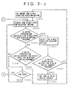
- Fig. 3 is a flow chart for explaining an operation of the embodiment.
- An individual information item at each address is selected by operating the item selecting switch 14 (step 101).
- an item in a wait state for selection setting is displayed (step 102).
- a switch operation for selection setting is performed (step 103)
- the item in the wait state for selection setting is selected (step 104).
- step 106 When the item is selected, whether to set the item as an item of special interest (step 106) is determined by a switch operation (step 105), and another item is set in a wait state for selection setting (step 107).
- step 108 When a switch operation is performed to set another item in a wait state for selection setting while the wait state for selection setting is displayed (steps 102 and 103), another item is set in a wait state for selection setting (step 108). When, however, a predetermined period of time elapses without operating the item selecting switch 14 (109), the item selection mode is terminated.
- step 110 When a switch operation is performed to display information (step 110), information associated with each item is displayed (step 111).
- a message is received (step 112), a specific portion of the message is collated with the selected item to check whether the message corresponds to the selected item (step 113).
- a change in the information is then checked by collating it with the latest information stored in the second memory 6b (step 114).
- step 115 When there is a change in the information associated with the selected item, it is checked whether the item is of special interest (step 115).
- a notifying sound is generated by the loudspeaker 13 (step 116).
- the information associated with the item is displayed (step 117), and the received information associated with the item is written in the second memory 6b to update the corresponding information (step 118).
- the item is not of a special interest (step 115)
- only display of the information (step 117) and updating of the information (step 118) are performed.
- Figs. 4A and 4B illustrate message display samples in the embodiment.
- Fig. 4A shows a display of information associated with each item. More specifically, "PARKING-LOT INFORMATION” is an information field corresponding to an address, and "YOKOHAMA STATION HIGASHIGUCHI DAIICHI” and “YOKOHAMA STATION NISHIGUCHI CHIKA” are individual information items. Two pieces of latest information “FULL” and "VACANT" are displayed on the right side of the respective items.
- Fig. 4B shows a message display in a case wherein a new message associated with the item "YOKOHAMA STATION HIGASHIGUCHI DAIICHI" is received.
- Fig. 5 is a block diagram showing the arrangement of the second embodiment.
- the components denoted by the same reference numerals and symbols as those in Fig. 2 have the same functions as those of the corresponding components. Therefore, a repetitive description of these components will be avoided.
- Fig. 5 shows the minimum necessary arrangement. This arrangement is different from the arrangement of the first embodiment shown in Fig. 2 in that a message memory control unit 9a is included in a CPU 9 in place of the second message collating section 8b.
- a received message h is stored in a second memory 6b in the following manner.
- a message collating section 8 checks upon collation whether a message code d output from a decoder 4 contains a character and symbol train identical to a specific character and symbol train e read out (control (2)) from a first memory 6a for storing a character and symbol train.
- the message collating section 8 then outputs a collation result f and the message h to the message memory control unit 9a. If the collation result indicates that the special character and symbol train is not contained, the message memory control unit 9a performs control (3) through a CPU 9 to store the received message h in the second memory 6b.
- the message memory control unit 9a erases a message containing the same character and symbol train and stored in the second memory 6b, and causes the second memory 6b to store the newly received message h .
- Figs. 7A and 7B illustrate messages displayed by the radio paging receiver shown in Fig. 5.
- Fig. 7A shows a case wherein a message stored in the second memory 6b is displayed until a new message is received. Assume that a new message "$ (YEN): 140" is received in this state. In this case, in the receiver shown in Fig. 5, it is considered that a new message containing the selected individual information item "$ (YEN):" is received. Therefore, a message 21 shown in Fig. 7A is erased, and a message 22 shown in Fig. 7B is stored.
- Fig. 6 is a flow chart showing an operation of the radio paging receiver with a display unit in Fig. 5.
- the latest message is displayed (step 202).
- the messages are sequentially displayed, from a message at the next memory number indicating a message storage location assigned to the second memory 6b (step 204).
- step 205 When a paging number corresponding to a self-address is received (step 205), it is checked upon collation whether a character and symbol train identical to a specific character and symbol train pre-stored in the first memory 6a is contained in the received message (step 206). In this case, the specific character and symbol train is "$ (YEN):”. If “$ (YEN):” is not contained in the received message, the new message is simply stored in the second memory 6b (step 207). If, however, "$ (YEN):” is contained in the received message, it is further checked whether a message containing "$ (YEN):” is stored in the second memory 6b (step 208).
- step 207 If a message containing "$ (YEN):" is stored, the message is erased, and the received message is stored in the second memory 6b instead (step 209). As is apparent, if a message containing "$ (YEN):” is not stored in the second memory 6b, the received message is simply stored in the second memory 6b (step 207).
Landscapes
- Physics & Mathematics (AREA)
- Engineering & Computer Science (AREA)
- Computer Networks & Wireless Communication (AREA)
- Electromagnetism (AREA)
- General Physics & Mathematics (AREA)
- Signal Processing (AREA)
- Mobile Radio Communication Systems (AREA)
Claims (5)
- Récepteur d'appel radio pourvu d'une unité d'affichage, le récepteur comprenant des moyens de mémorisation/d'affichage (6b, 7, 9) et des moyens d'actualisation (6b, 8a, 8b, 9), caractérisé en ce que ledit récepteur est conçu pour recevoir un signal comprenant un numéro d'appel correspondant à un champ d'informations devant être reçu par le récepteur, une partie spécifique d'un message contenu dans ledit signal et correspondant à un item individuel d'informations, dans le champ d'informations, devant être reçu, et une partie restante du message correspondant aux informations associées à l'item d'informations, le récepteur comprenant, en outre :des moyens d'entrée (6a, 7, 9, 14) destinés à sélectionner un item individuel d'informations devant être reçu ;des moyens de mémorisation/d'affichage (6b, 7, 9) étant conçus pour mémoriser et afficher un item individuel d'informations sélectionné par lesdits moyens d'entrée ainsi que les informations associées à l'item d'informations ; etles moyens d'actualisation (6b, 8a, 8b, 9) étant conçus pour actualiser automatiquement lesdits moyens de mémorisation/d'affichage lors de la réception d'un nouveau message uniquement lorsque la partie spécifique du message correspond à l'item individuel d'informations sélectionné ayant été mémorisé dans lesdits moyens de mémorisation/d'affichage et que les informations associées à l'item d'informations varient par rapport à celles mémorisées dans lesdits moyens de mémorisation/d'affichage.
- Récepteur selon la revendication 1, dans lequel lesdits moyens d'entrée sont conçus pour sélectionner, en outre, un important item individuel d'informations, et ledit récepteur comprend, en outre, des moyens de notification (7) destinés à délivrer une notification spéciale lorsque le contenu des informations associées à l'item individuel d'informations sélectionné varie.
- Récepteur selon la revendication 1, dans lequel lesdits moyens d'entrée incluent une première mémoire (6a) destinée à mémoriser un train de caractères et de symboles spécial, une CPU (9) destinée à commander ladite première mémoire, et une unité de notification/d'affichage (7) commandée par ladite CPU ; lesdits moyens de mémorisation/d'affichage incluent une seconde mémoire (6b) destinée à mémoriser le message reçu, ladite unité de notification/d'affichage (7) et ladite CPU (9) destinée à commander ladite seconde mémoire (6b) et ladite unité de notification/d'affichage (7) ; et lesdits moyens d'actualisation incluent une unité d'interclassement de messages (8a), une unité de commande de mémoire de messages (9) et ladite seconde mémoire (6b).
- Récepteur selon la revendication 3, dans lequel, lors de la détermination par ladite unité d'interclassement de messages (8a) qu'un premier message contenant le train de caractères et de symboles spécifique a déjà été mémorisé dans ladite seconde mémoire (6b) et que le train de caractères et de symboles spécifique est contenu dans un second message nouvellemennt reçu, ladite unité de commande de mémoire de messages (9) est conçue pour effacer le premier message et amener ladite seconde mémoire (6b) à mémoriser le second message.
- Récepteur selon la revendication 1, dans lequel lesdits moyens d'entrée incluent un commutateur de sélection d'item (14) destiné à fixer l'item individuel d'informations, une première mémoire (6a) destinée à mémoriser à la fois un item individuel d'informations préfixé et des informations indiquant si l'item d'informations à été sélectionné ou non en tant qu'item de réception souhaité par un étage de transmission dudit récepteur, une unité de notification/d'affichage (7) et une CPU (9) destinée à commander ladite première mémoire et ladite unité de notification/d'affichage ; lesdits moyens de mémorisation/d'affichage incluent une seconde mémoire (6b) destinée à mémoriser les informations transmises dans un message et associées à un item individuel d'informations sélectionné, ladite unité de notification/d'affichage (7), et ladite CPU (9) destinée à commander ladite seconde mémoire et ladite unité de notification/d'affichage ; et lesdits moyens d'actualisation incluent un premier étage d'interclassement de messages (8a), un second étage d'interclassement de messages (8b) destiné à recevoir les informations associées à l'item individuel d'informations sélectionné en provenance dudit premier étage d'interclassement de messages, à interclasser les informations par leur contenu mémorisé de ladite seconde mémoire afin de déterminer la présence/l'absence d'une variation du contenu des informations et à délivrer le résultat de la détermination auprès de ladite CPU (9) et de ladite seconde mémoire (6b).
Applications Claiming Priority (4)
| Application Number | Priority Date | Filing Date | Title |
|---|---|---|---|
| JP04182387A JP3076151B2 (ja) | 1992-07-09 | 1992-07-09 | 表示付き無線選択呼出受信機 |
| JP182387/92 | 1992-07-09 | ||
| JP28566992A JP3060754B2 (ja) | 1992-10-23 | 1992-10-23 | 表示付き無線選択呼出受信機 |
| JP285669/92 | 1992-10-23 |
Publications (2)
| Publication Number | Publication Date |
|---|---|
| EP0583064A1 EP0583064A1 (fr) | 1994-02-16 |
| EP0583064B1 true EP0583064B1 (fr) | 1999-05-19 |
Family
ID=26501205
Family Applications (1)
| Application Number | Title | Priority Date | Filing Date |
|---|---|---|---|
| EP93305359A Expired - Lifetime EP0583064B1 (fr) | 1992-07-09 | 1993-07-08 | Récepteur d'appel radio avec unité d'affichage |
Country Status (5)
| Country | Link |
|---|---|
| US (1) | US5764157A (fr) |
| EP (1) | EP0583064B1 (fr) |
| KR (1) | KR940006357A (fr) |
| CN (1) | CN1082322C (fr) |
| DE (1) | DE69324969T2 (fr) |
Families Citing this family (11)
| Publication number | Priority date | Publication date | Assignee | Title |
|---|---|---|---|---|
| DE4412023B4 (de) * | 1994-04-07 | 2005-03-10 | Deutsche Telekom Ag | Verfahren und Anordnung zum Empfang von codiert übertragenen Informationen |
| JPH0918920A (ja) * | 1995-06-29 | 1997-01-17 | Sony Corp | 無線呼び出しシステム及びその受信端末装置 |
| US5604921A (en) * | 1995-07-07 | 1997-02-18 | Nokia Mobile Phones Ltd. | Radiotelephone user interface for broadcast short message service |
| BR9611408A (pt) * | 1995-11-06 | 1999-01-05 | Motorola Inc | Receptor seletivo de chamada e método para armazenar mensagens do mesmo |
| JPH09261704A (ja) * | 1996-03-27 | 1997-10-03 | Nec Shizuoka Ltd | 無線選択呼出受信機 |
| JPH10215473A (ja) * | 1997-01-29 | 1998-08-11 | Nec Shizuoka Ltd | 無線選択呼出受信機 |
| GB9704951D0 (en) * | 1997-03-11 | 1997-04-30 | Philips Electronics Nv | Message transmission system, a method of operating the message transmission system and a primary station therefor |
| FI973945A (fi) | 1997-10-13 | 1999-04-14 | Nokia Telecommunications Oy | Lyhytsanomia välittävä tiedonsiirtojärjestelmä |
| FR2770957B1 (fr) * | 1997-11-07 | 2002-04-26 | Jacques Lewiner | Recepteur de radio-messagerie unilaterale |
| JP3574119B2 (ja) * | 2002-05-14 | 2004-10-06 | 株式会社スクウェア・エニックス | ネットワークゲームシステム、ビデオゲーム装置、プログラム、及び記録媒体 |
| US8296151B2 (en) | 2010-06-18 | 2012-10-23 | Microsoft Corporation | Compound gesture-speech commands |
Family Cites Families (19)
| Publication number | Priority date | Publication date | Assignee | Title |
|---|---|---|---|---|
| JPS5834836B2 (ja) * | 1975-12-29 | 1983-07-29 | 株式会社日立製作所 | デ−タヒヨウジセイギヨホウシキ |
| US4237448A (en) * | 1979-04-30 | 1980-12-02 | Motorola, Inc. | Pager with escalating audio alert signal level |
| US4412217A (en) * | 1981-09-29 | 1983-10-25 | Motorola, Inc. | Pager with visible display indicating status of memory |
| JPS60191531A (ja) * | 1984-03-13 | 1985-09-30 | Nec Corp | 表示機能付無線選択呼出受信機 |
| SE445786B (sv) * | 1984-11-26 | 1986-07-14 | Ericsson Telefon Ab L M | Forfarande for att vid radiomottagning undvika att lagra ett meddelande mer en en gang samt mottagare for endamalet |
| GB8501276D0 (en) * | 1985-01-18 | 1985-02-20 | Multitone Electronics Plc | Radio pager |
| JPH0669163B2 (ja) * | 1985-09-17 | 1994-08-31 | 日本電気株式会社 | 表示機能付無線選択呼出受信機 |
| US4845491A (en) * | 1987-05-15 | 1989-07-04 | Newspager Corporation Of America | Pager based information system |
| US4952927A (en) * | 1987-08-05 | 1990-08-28 | Motorola, Inc. | Paging receiver with dynamically allocated display rate |
| JPH01116132A (ja) * | 1987-10-27 | 1989-05-09 | Sumitomo Rubber Ind Ltd | 周囲拘束型の免震装置 |
| JP2776503B2 (ja) * | 1987-11-13 | 1998-07-16 | 日本電気株式会社 | 無線選択呼出受信機 |
| US4839628A (en) * | 1988-01-11 | 1989-06-13 | Motorola, Inc. | Paging receiver having selectively protected regions of memory |
| GB8908513D0 (en) * | 1989-04-14 | 1989-06-01 | Blick Communications Ltd | Radio pagers |
| WO1990015511A1 (fr) * | 1989-05-30 | 1990-12-13 | Motorola, Inc. | Procede et appareil de retransmission |
| US5107259A (en) * | 1989-06-12 | 1992-04-21 | Motorola, Inc. | Means and method of displaying a message in a plurality of scripts |
| US5173688A (en) * | 1990-01-02 | 1992-12-22 | Motorola, Inc. | Pager with display updateable by incoming message |
| US5182553A (en) * | 1990-09-04 | 1993-01-26 | Motorola, Inc. | Communication receiver providing displayed operating instructions |
| JP2864743B2 (ja) * | 1990-12-20 | 1999-03-08 | 日本電気株式会社 | 無線選択呼出し方式およびそれに用いる受信機 |
| EP0593731A4 (en) * | 1992-05-08 | 1997-05-28 | Motorola Inc | Method and apparatus for quick access to selected updated information in a selective call receiver |
-
1993
- 1993-07-08 DE DE69324969T patent/DE69324969T2/de not_active Expired - Fee Related
- 1993-07-08 EP EP93305359A patent/EP0583064B1/fr not_active Expired - Lifetime
- 1993-07-09 KR KR1019930012906A patent/KR940006357A/ko not_active Application Discontinuation
- 1993-07-09 CN CN93109884A patent/CN1082322C/zh not_active Expired - Fee Related
-
1997
- 1997-05-08 US US08/855,697 patent/US5764157A/en not_active Expired - Fee Related
Also Published As
| Publication number | Publication date |
|---|---|
| US5764157A (en) | 1998-06-09 |
| DE69324969T2 (de) | 1999-09-16 |
| CN1082322C (zh) | 2002-04-03 |
| CN1085028A (zh) | 1994-04-06 |
| DE69324969D1 (de) | 1999-06-24 |
| KR940006357A (ko) | 1994-03-23 |
| EP0583064A1 (fr) | 1994-02-16 |
Similar Documents
| Publication | Publication Date | Title |
|---|---|---|
| US5173688A (en) | Pager with display updateable by incoming message | |
| US5465088A (en) | Receiver for traffic messages | |
| EP0583064B1 (fr) | Récepteur d'appel radio avec unité d'affichage | |
| US6032024A (en) | Call receiver having a display for displaying portions of a received message in different colors | |
| EP0748134B1 (fr) | Récepteur-radio d'appel sélectif à capabilité d'affichage de message | |
| US5652572A (en) | Radio pager capable of displaying fixed sentences | |
| JPH09322214A (ja) | 選択呼出受信装置 | |
| US6081200A (en) | Single ID radio pager for receiving traffic status data | |
| JPH0750951B2 (ja) | ページングシステム | |
| KR970055767A (ko) | 무선호출수신기의 문자수신 표시장치 및 방법 | |
| EP0661678B1 (fr) | Structure d'un récepteur d'appel et méthode de commande de stockage de messages | |
| WO1992008221A1 (fr) | Recepteur d'appels selectif comportant un indicateur de message reçu | |
| JP3060754B2 (ja) | 表示付き無線選択呼出受信機 | |
| US5844499A (en) | Method and apparatus for recovering erased calling messages in radio pager | |
| US6201959B1 (en) | Radio selective call receiver and method for storing received message | |
| JP3076151B2 (ja) | 表示付き無線選択呼出受信機 | |
| US6069568A (en) | Multi-address radio display pager having on/off setting mode for displaying ancillary data | |
| US5794122A (en) | Radio selective call receiver with sentence memory | |
| JP2591061B2 (ja) | メッセージ受信機 | |
| KR19980024749A (ko) | 무선 선택 호출 수신기 | |
| KR100247580B1 (ko) | 메시지 분할 기능을 갖춘 무선 선택 호출 수신기 | |
| JPH03175827A (ja) | 選択呼出受信装置 | |
| EP0499246B1 (fr) | Récepteur d'appel radio et procédé pour écrire de l'information dans le ROM du récepteur d'appel | |
| US5721988A (en) | Data imprinting device of camera | |
| US5955962A (en) | Radio selective calling receiver |
Legal Events
| Date | Code | Title | Description |
|---|---|---|---|
| PUAI | Public reference made under article 153(3) epc to a published international application that has entered the european phase |
Free format text: ORIGINAL CODE: 0009012 |
|
| AK | Designated contracting states |
Kind code of ref document: A1 Designated state(s): DE GB NL |
|
| 17P | Request for examination filed |
Effective date: 19940120 |
|
| 17Q | First examination report despatched |
Effective date: 19961212 |
|
| GRAG | Despatch of communication of intention to grant |
Free format text: ORIGINAL CODE: EPIDOS AGRA |
|
| GRAG | Despatch of communication of intention to grant |
Free format text: ORIGINAL CODE: EPIDOS AGRA |
|
| GRAH | Despatch of communication of intention to grant a patent |
Free format text: ORIGINAL CODE: EPIDOS IGRA |
|
| GRAH | Despatch of communication of intention to grant a patent |
Free format text: ORIGINAL CODE: EPIDOS IGRA |
|
| GRAA | (expected) grant |
Free format text: ORIGINAL CODE: 0009210 |
|
| AK | Designated contracting states |
Kind code of ref document: B1 Designated state(s): DE GB NL |
|
| REF | Corresponds to: |
Ref document number: 69324969 Country of ref document: DE Date of ref document: 19990624 |
|
| PLBE | No opposition filed within time limit |
Free format text: ORIGINAL CODE: 0009261 |
|
| STAA | Information on the status of an ep patent application or granted ep patent |
Free format text: STATUS: NO OPPOSITION FILED WITHIN TIME LIMIT |
|
| 26N | No opposition filed | ||
| PGFP | Annual fee paid to national office [announced via postgrant information from national office to epo] |
Ref country code: NL Payment date: 20010730 Year of fee payment: 9 |
|
| REG | Reference to a national code |
Ref country code: GB Ref legal event code: IF02 |
|
| PG25 | Lapsed in a contracting state [announced via postgrant information from national office to epo] |
Ref country code: NL Free format text: LAPSE BECAUSE OF NON-PAYMENT OF DUE FEES Effective date: 20030201 |
|
| NLV4 | Nl: lapsed or anulled due to non-payment of the annual fee |
Effective date: 20030201 |
|
| PGFP | Annual fee paid to national office [announced via postgrant information from national office to epo] |
Ref country code: GB Payment date: 20040707 Year of fee payment: 12 |
|
| PGFP | Annual fee paid to national office [announced via postgrant information from national office to epo] |
Ref country code: DE Payment date: 20040715 Year of fee payment: 12 |
|
| PG25 | Lapsed in a contracting state [announced via postgrant information from national office to epo] |
Ref country code: GB Free format text: LAPSE BECAUSE OF NON-PAYMENT OF DUE FEES Effective date: 20050708 |
|
| PG25 | Lapsed in a contracting state [announced via postgrant information from national office to epo] |
Ref country code: DE Free format text: LAPSE BECAUSE OF NON-PAYMENT OF DUE FEES Effective date: 20060201 |
|
| GBPC | Gb: european patent ceased through non-payment of renewal fee |
Effective date: 20050708 |