US5764157A - Radio paging receiver with display unit having update means to eliminate redundant messages - Google Patents
Radio paging receiver with display unit having update means to eliminate redundant messages Download PDFInfo
- Publication number
- US5764157A US5764157A US08/855,697 US85569797A US5764157A US 5764157 A US5764157 A US 5764157A US 85569797 A US85569797 A US 85569797A US 5764157 A US5764157 A US 5764157A
- Authority
- US
- United States
- Prior art keywords
- message
- memory
- item
- information item
- individual information
- Prior art date
- Legal status (The legal status is an assumption and is not a legal conclusion. Google has not performed a legal analysis and makes no representation as to the accuracy of the status listed.)
- Expired - Fee Related
Links
- 230000015654 memory Effects 0.000 claims description 84
- 230000008859 change Effects 0.000 claims description 14
- 238000010586 diagram Methods 0.000 description 5
- 230000006870 function Effects 0.000 description 1
- 239000004973 liquid crystal related substance Substances 0.000 description 1
- 230000004048 modification Effects 0.000 description 1
- 238000012986 modification Methods 0.000 description 1
- 230000003252 repetitive effect Effects 0.000 description 1
- 230000004044 response Effects 0.000 description 1
Images


Classifications
-
- H—ELECTRICITY
- H04—ELECTRIC COMMUNICATION TECHNIQUE
- H04B—TRANSMISSION
- H04B5/00—Near-field transmission systems, e.g. inductive loop type
-
- G—PHYSICS
- G08—SIGNALLING
- G08B—SIGNALLING OR CALLING SYSTEMS; ORDER TELEGRAPHS; ALARM SYSTEMS
- G08B5/00—Visible signalling systems, e.g. personal calling systems, remote indication of seats occupied
- G08B5/22—Visible signalling systems, e.g. personal calling systems, remote indication of seats occupied using electric transmission; using electromagnetic transmission
- G08B5/222—Personal calling arrangements or devices, i.e. paging systems
- G08B5/223—Personal calling arrangements or devices, i.e. paging systems using wireless transmission
- G08B5/224—Paging receivers with visible signalling details
- G08B5/227—Paging receivers with visible signalling details with call or message storage means
Definitions
- the present invention relates to a radio paging receiver with a display unit and, more particularly, to a radio paging receiver with a display unit which can effectively use a limited memory area.
- a received message is stored in a memory and can be displayed upon reception. In this case, if an identical message is received, the message is not stored in the memory. Otherwise, every time a new message is received, a message display operation is performed for notification, and the message is stored in the memory.
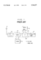
- FIG. 1 is a block diagram showing an arrangement of a conventional radio paging receiver with a display unit.
- a radio signal received through an antenna 21 is amplified and demodulated by a radio section 22 and is input, as a digital signal B, to a decoder 24.
- the decoder 24 collates an address contained in this digital signal, i.e., a paging number, with a self-address C stored in an ID memory 25. If they coincide with each other, a CPU 28 stores a message code D accompanying the address code in a message memory 26, and outputs a control signal (3) for controlling a notification/display means 27 to perform a notification and display a message E.
- Reading of the self-address C from the ID memory 25 is performed by using a control signal (1) from the decoder 24 and reading/writing of the message D from/in the message memory 26 is performed by using a control signal (2) from the CPU 28. If the received message is stored in the message memory 26, the message D or E stored in the message memory 26 can be displayed by the notification/display means 27 using control signals (2) and (3) from the CPU 28.
- a control section 23 consists of the decoder 24 and the CPU 28.
- a radio paging receiver with a display unit comprises a first memory for storing a specific character and symbol train, and a second memory for storing a received message.
- Message collating means are also provided for determining whether the specific character and symbol train is contained in the received message as well as second memory control means for controlling storage of the received message in the second memory on the basis of the determination result obtained by the message collating means.
- the second memory control means erases the first message and causes the second memory to newly store the second message.
- the radio paging receiver with a display unit further comprises input means for selecting an individual information item to be received, storage/display means for storing and displaying the individual information item selected by the input means and information associated with the information item, and update means for updating the storage/display means upon reception of a new message only when a specific portion of the message corresponds to the selected individual information item, and contents of information associated with the information item change.
- the received paging number is contained in a received information field, a specific portion of a received message corresponds to an individual information item, in the information field, which is to be received, and a remaining portion of the message corresponds to information associated with the information item.
- the radio paging receiver with a display unit further comprises input means for, when the individual information item to be received is selected, further selecting an important individual information item, and notifying means for performing a special notification when contents of information associated with the selected important individual information item change.
- the radio paging receiver with a display unit of the present invention it is checked whether a specific character and symbol train is contained in a received message. If it is determined that a first message containing the specific character and symbol train has already been stored in the second memory, and the specific character and symbol train is also contained in a newly received second message, the first message is erased, and the second message is stored in the second memory. With this operation, when a new message associated with an item defined by a specific character and symbol train, i.e., a specific item, is received, an old message stored in the message memory is erased, and one latest message can be stored.
- an individual information item to be received is selected, and the selected individual information item and information associated therewith are stored and displayed.
- the stored contents are replaced with a newly received message only when a specific portion of the received message corresponds to a selected information item, and the contents of information associated with the information item change.
- an important individual information item is further selected. If the contents of information associated with the selected important individual information item change, a special notification is performed. With this operation, when a large number of messages whose contents change with time with respect to specific items are received, messages indicating the current states of specific contents can be efficiently received.
- FIG. 1 is a block diagram showing the arrangement of a conventional radio paging receiver with a display unit
- FIG. 2 is a block diagram showing the arrangement of an embodiment of the present invention
- FIGS. 3A and 3B together form a flow chart associated with an operation of the embodiment shown in FIG. 2;
- FIGS. 4A and 4B illustrate display samples in the embodiment shown in FIG. 2;
- FIG. 5 is a block diagram showing the arrangement of another embodiment of the present invention.
- FIG. 6 is a flow chart associated with an operation of the embodiment shown in FIG. 5;
- FIGS. 7A and 7B illustrate display samples in the embodiment shown in FIG. 5.
- the embodiment shown in FIG. 2 comprises an antenna 1, a radio section 2 for demodulating a received input signal a to output a digital signal b as a paging number, a decoder 4 for receiving and decoding the output signal b from the radio section 2, an ID memory 5 for storing a self-address, a first memory 6a for storing both a preset individual information item and information indicating whether the individual information item is selected as a desired reception item by a carrier of the receiver, a first message collating section 8a for collating a message code output from the decoder 4 with the individual information item in the first memory 6a, a CPU 9, a second memory 6b for storing detailed information associated with a selected individual information item sent through a message, and a second message collating section 8b for receiving the information associated with the selected individual information item from the first message collating section 8a, collating the information with the stored contents of the second memory 6b to check a change in information contents, and sending the resultant data to the CPU 9.
- the embodiment also comprises an LCD driver 10, an LCD 11, a loudspeaker driving section 12, and a loudspeaker 13, which are included in a notification/display means 7, and an item selecting switch 14 for setting an individual information item.
- a control section 3 is constituted by the first and second message collating sections 8a and 8b, the decoder 4, and the CPU 9.
- the item selecting switch 14 and its cooperative components such as the CPU 9, the LCD driver 10, the LCD11, the first memory 6a constitute an input means; the second memory 6b, the CPU 9, the LCD driver 10, and the LCD 11 constitute a storage/display means; the first and second message collating sections 8a and 8b, and the second memory 6b constitute an update means; and the first and second memories 6a and 6b, the first and second message collating sections 8a and 8b, the CPU 9, the LCD driver 10, the LCD 11, the loudspeaker driving section 12, and the loudspeaker 13 also serve as a notification means.
- the radio signal a received by the antenna 1 is amplified and demodulated by the radio section 2 and is input, as the digital signal b, to the decoder 4.
- the decoder 4 collates an address contained in the digital signal b, i.e., the paging number, with a self-address c stored in the ID memory 5. When they coincide with each other, the decoder 4 outputs a message code d accompanying the address code to the first message collating section 8a. In this case, the self-address c is read out from the ID memory 5 under the control (1) of the decoder 4.
- the self-address used in this case corresponds to the field of information sent through a message, e.g., "PARKING-LOT INFORMATION" or "AIRLINE TICKET VACANCY STATE" rather than an address unique to the radio paging receiver with a display unit (to be referred to as the receiver hereinafter).
- the first memory 6a serves to store a character and symbol train transmitted as a specific portion of a message corresponding to an individual information item preset with respect to such an address, which item is, for example, "YOKOHAMA STATION HIGASHIGUCHI DAIICHI” or "YOKOHAMA STATION NISHIGUCHI CHIKA” for "PARKING-LOT INFORMATION".
- the first memory 6a also stores information indicating whether such an individual information item is selected, as an item to be received, by the, carrier of the receiver.
- control (2) When the message code d is input to the first message collating section 8a, a selected individual information item e 1 stored in the first memory 6a is referred to (control (2)), and a specific portion of the message is collated with the selected individual item to check whether they correspond to each other. A collation result f 1 is output to the second message collating section 8b.
- Information g transmitted through the message and associated with the selected individual information item e 1 is stored in the second memory 6b.
- the second message collating section 8b Upon reception of the collation result f 1 from the first message collating section 8a, the second message collating section 8b compares the information portion, of the received message, which is associated with the individual information item with the current information g by referring to the second memory 6b (control (3)) so as to check whether the contents of the information have changed.
- the second message collating section 8b outputs the resultant data to the CPU 9.
- the CPU 9 Upon reception of an output f 2 from the second message collating section 8b, which output indicates that new information associated with the individual information item is received, the CPU 9 receives a received message i from the decoder 4 and performs loudspeaker control (4) of the loudspeaker driving section 12 to cause the loudspeaker 13 to generate a notifying sound j. In addition, the CPU 9 performs driver control (4') of the LCD (Liquid Crystal Display) driver 10 to cause the LCD 11 to display a message k, and writes new information h in the second memory 6b to update the corresponding information.
- driver control (4') of the LCD (Liquid Crystal Display) driver 10 to cause the LCD 11 to display a message k, and writes new information h in the second memory 6b to update the corresponding information.
- the information g or h stored in the second memory 6b can be read out by the CPU 9 (control (5)) and can be displayed on the LCD 11 upon driver control (4') of the LCD driver 10.
- the CPU 9 In order to set each individual information item, the CPU 9 writes selected information n associated with each individual information item in the first memory 6a in response to a signal m input to the item selecting switch 14.
- the selecting operation can be easily performed while displaying items of selection on the LCD 11.
- the CPU 9 controls the loudspeaker driving section 12 to generate a special notifying sound from the loudspeaker 13.
- the special notifying sound may be a sound whose volume, frequency, tone, or the like is different from that of a normal notifying sound.
- a notifying sound may be generated even in a situation wherein no notifying sound is generated upon reception of a normal item.
- FIG. 3 is a flow chart for explaining an operation of the embodiment.
- An individual information item at each address is selected by operating the item selecting switch 14 (step 101).
- an item in a wait state for selection setting is displayed (step 102).
- a switch operation for selection setting is performed (step 103)
- the item in the wait state for selection setting is selected (step 104).
- step 106 When the item is selected, whether to set the item as an item of special interest (step 106) is determined by a switch operation (step 105), and another item is set in a wait state for selection setting (step 107).
- step 108 When a switch operation is performed to set another item in a wait state for selection setting while the wait state for selection setting is displayed (steps 102 and 103), another item is set in a wait state for selection setting (step 108). When, however, a predetermined period of time elapses without operating the item selecting switch 14 (109), the item selection mode is terminated.
- step 110 When a switch operation is performed to display information (step 110), information associated with each item is displayed (step 111).
- a message is received (step 112), a specific portion of the message is collated with the selected item to check whether the message corresponds to the selected item (step 113).
- a change in the information is then checked by collating it with the latest information stored in the second memory 6b (step 114).
- step 115 When there is a change in the information associated with the selected item, it is checked whether the item is of special interest (step 115).
- a notifying sound is generated by the loudspeaker 13 (step 116).
- the information associated with the item is displayed (step 117), and the received information associated with the item is written in the second memory 6b to update the corresponding information (step 118).
- the item is not of a special interest (step 115)
- only display of the information (step 117) and updating of the information (step 118) are performed.
- FIGS. 4A and 4B illustrate message display samples in the embodiment.
- FIG. 4A shows a display of information associated with each item. More specifically, "PARKING-LOT INFORMATION” is an information field corresponding to an address, and "YOKOHAMA STATION HIGASHIGUCHI DAIICHI” and “YOKOHAMA STATION NISHIGUCHI CHIKA” are individual information items. Two pieces of latest information “FULL” and "VACANT" are displayed on the right side of the respective items.
- FIG. 4B shows a message display in a case wherein a new message associated with the item "YOKOHAMA STATION HIGASHIGUCHI DAIICHI" is received.
- FIG. 5 is a block diagram showing the arrangement of the second embodiment.
- the components denoted by the same reference numerals and symbols as those in FIG. 2 have the same functions as those of the corresponding components. Therefore, a repetitive description of these components will be avoided.
- FIG. 5 shows the minimum necessary arrangement. This arrangement is different from the arrangement of the first embodiment shown in FIG. 2 in that a message memory control unit 9a is included in a CPU 9 in place of the second message collating section 8b.
- a received message h is stored in a second memory 6b in the following manner.
- a message collating section 8 checks upon collation whether a message code d output from a decoder 4 contains a character and symbol train identical to a specific character and symbol train e read out (control (2)) from a first memory 6a for storing a character and symbol train.
- the message collating section 8 then outputs a collation result f and the message h to the message memory control unit 9a. If the collation result indicates that the special character and symbol train is not contained, the message memory control unit 9a performs control (3) through a CPU 9 to store the received message h in the second memory 6b.
- the message memory control unit 9a erases a message containing the same character and symbol train and stored in the second memory 6b, and causes the second memory 6b to store the newly received message h.
- FIGS. 7A and 7B illustrate messages displayed by the radio paging receiver shown in FIG. 5.
- FIG. 7A shows a case wherein a message stored in the second memory 6b is displayed until a new message is received. Assume that a new message "$ (YEN): 140) is received in this state. In this case, in the receiver shown in FIG. 5, it is considered that a new message containing the selected individual information item "$ (YEN):" is received. Therefore, a message 21 shown in FIG. 7A is erased, and a message 22 shown in FIG. 7B is stored.
- FIG. 6 is a flow chart showing an operation of the radio paging receiver with a display unit in FIG. 5.
- the latest message is displayed (step 202).
- the messages are sequentially displayed, from a message at the next memory number indicating a message storage location assigned to the second memory 6b (step 204).
- step 205 When a paging number corresponding to a self-adress is received (step 205), it is checked upon collation whether a character and symbol train identical to a specific character and symbol train pre-stored in the first memory 6a is contained in the received message (step 206). In this case, the specific character and symbol train is "$ (YEN):”. If “$ (YEN):” is not contained in the received message, the new message is simply stored in the second memory 6b (step 207). If, however, "$ (YEN):” is contained in the received message, it is further checked whether a message containing "$ (YEN):” is stored in the second memory 6b (step 208).
- step 207 If a message containing "$ (YEN):" is stored, the message is erased, and the received message is stored in the second memory 6b instead (step 209). As is apparent, if a message containing "$ (YEN):” is not stored in the second memory 6b, the received message is simply stored in the second memory 6b (step 207).
Abstract
In a radio paging receiver with a display unit, a paging number corresponds to an information field to be received, a special portion of a message corresponds to an individual information item, in the information field, which is to be received, and the remaining portion of the message corresponds to information associated with the information item. The receiver comprises an input section for selecting an individual information item to be received, a storage/display section for storing and displaying an individual information item selected by the input section and information associated with the information item, and an update section for updating the storage/display section upon reception of a new message only when (a) a specific portion of the message corresponds to the selected individual information item, and (b) information associated with the information item changes.
Description
This application is a continuation of application Ser. No. 08/544,561, filed Oct. 18, 1995, now abandoned, which is a continuation of Ser. No. 08/086,844, filed Jul. 7, 1993, now abandoned.
1. Field of the Invention
The present invention relates to a radio paging receiver with a display unit and, more particularly, to a radio paging receiver with a display unit which can effectively use a limited memory area.
2. Description of the Prior Art
In a conventional radio paging receiver with a display unit, a received message is stored in a memory and can be displayed upon reception. In this case, if an identical message is received, the message is not stored in the memory. Otherwise, every time a new message is received, a message display operation is performed for notification, and the message is stored in the memory.
FIG. 1 is a block diagram showing an arrangement of a conventional radio paging receiver with a display unit.
Referring to FIG. 1, a radio signal received through an antenna 21 is amplified and demodulated by a radio section 22 and is input, as a digital signal B, to a decoder 24. The decoder 24 collates an address contained in this digital signal, i.e., a paging number, with a self-address C stored in an ID memory 25. If they coincide with each other, a CPU 28 stores a message code D accompanying the address code in a message memory 26, and outputs a control signal (3) for controlling a notification/display means 27 to perform a notification and display a message E. Reading of the self-address C from the ID memory 25 is performed by using a control signal (1) from the decoder 24 and reading/writing of the message D from/in the message memory 26 is performed by using a control signal (2) from the CPU 28. If the received message is stored in the message memory 26, the message D or E stored in the message memory 26 can be displayed by the notification/display means 27 using control signals (2) and (3) from the CPU 28. A control section 23 consists of the decoder 24 and the CPU 28.
In the conventional radio paging receiver with a display unit, however, if a large number of similar messages and messages whose contents change with time in association with specific items are received, a large number of unnecessary messages, confusing messages, and messages expressing the current states of specific contents are stored. Consequently, a cumbersome operation is required to select a useful message, and a limited message memory area cannot be effectively used, resulting in a large increase in transmitted data.
It is an object of the present invention to provide a radio paging receiver with a display unit, in which only one latest message associated with an item defined by a specific character and symbol train, i.e., a specific item, is always stored, and old messages with little necessity and confusing messages are automatically removed when a large number of similar messages and messages whose contents change with time in association with specific items are received, whereby selection of a useful message is facilitated in a message display operation, and the limited message memory area can be effectively used.
In order to achieve the above object, according to the first aspect of the present invention, a radio paging receiver with a display unit comprises a first memory for storing a specific character and symbol train, and a second memory for storing a received message. Message collating means are also provided for determining whether the specific character and symbol train is contained in the received message as well as second memory control means for controlling storage of the received message in the second memory on the basis of the determination result obtained by the message collating means.
According to the second aspect of the present invention, in the radio paging receiver with a display unit according to the first aspect, when the message collating means determines that a first message containing the specific character and symbol train has already been stored in the second memory, and the specific character and symbol train is also contained in a newly received second message, the second memory control means erases the first message and causes the second memory to newly store the second message.
According to the third aspect of the present invention, the radio paging receiver with a display unit according to the first aspect further comprises input means for selecting an individual information item to be received, storage/display means for storing and displaying the individual information item selected by the input means and information associated with the information item, and update means for updating the storage/display means upon reception of a new message only when a specific portion of the message corresponds to the selected individual information item, and contents of information associated with the information item change. The received paging number is contained in a received information field, a specific portion of a received message corresponds to an individual information item, in the information field, which is to be received, and a remaining portion of the message corresponds to information associated with the information item.
In addition, according to the fourth aspect of the present invention, the radio paging receiver with a display unit according to the third aspect further comprises input means for, when the individual information item to be received is selected, further selecting an important individual information item, and notifying means for performing a special notification when contents of information associated with the selected important individual information item change.
According to the radio paging receiver with a display unit of the present invention, it is checked whether a specific character and symbol train is contained in a received message. If it is determined that a first message containing the specific character and symbol train has already been stored in the second memory, and the specific character and symbol train is also contained in a newly received second message, the first message is erased, and the second message is stored in the second memory. With this operation, when a new message associated with an item defined by a specific character and symbol train, i.e., a specific item, is received, an old message stored in the message memory is erased, and one latest message can be stored. Therefore, only one latest message associated with an item defined by a specific character and symbol train, i.e., a specific item, is always stored, and old messages with little necessity and confusing messages are automatically removed when a large number of similar messages and messages whose contents change with time in association with specific items are received, whereby selection of a useful message is facilitated in a message display operation, and the limited message memory area can be effectively used.
In addition, according to the present invention, in the radio paging receiver with a display unit, an individual information item to be received is selected, and the selected individual information item and information associated therewith are stored and displayed. The stored contents are replaced with a newly received message only when a specific portion of the received message corresponds to a selected information item, and the contents of information associated with the information item change. After an individual information item to be received is selected, an important individual information item is further selected. If the contents of information associated with the selected important individual information item change, a special notification is performed. With this operation, when a large number of messages whose contents change with time with respect to specific items are received, messages indicating the current states of specific contents can be efficiently received. A large number of old messages with little necessity and confusing messages are not stored, and a cumbersome operation of selecting a useful message need not be performed. Therefore, a limited message memory area can be effectively used, and information which are required to be obtained in real time can be effectively ensured.
The above and many other advantages, features and additional objects of the present invention will become manifest to those versed in the art upon making reference to the following detailed description and accompanying drawings in which preferred structural embodiments incorporating the principles of the present invention are shown by way of illustrative example.
FIG. 1 is a block diagram showing the arrangement of a conventional radio paging receiver with a display unit;
FIG. 2 is a block diagram showing the arrangement of an embodiment of the present invention;
FIGS. 3A and 3B together form a flow chart associated with an operation of the embodiment shown in FIG. 2;
FIGS. 4A and 4B illustrate display samples in the embodiment shown in FIG. 2;
FIG. 5 is a block diagram showing the arrangement of another embodiment of the present invention;
FIG. 6 is a flow chart associated with an operation of the embodiment shown in FIG. 5; and
FIGS. 7A and 7B illustrate display samples in the embodiment shown in FIG. 5.
The present invention will be described in more detail below in association with the preferred embodiments shown in the accompanying drawings.
The embodiment shown in FIG. 2 comprises an antenna 1, a radio section 2 for demodulating a received input signal a to output a digital signal b as a paging number, a decoder 4 for receiving and decoding the output signal b from the radio section 2, an ID memory 5 for storing a self-address, a first memory 6a for storing both a preset individual information item and information indicating whether the individual information item is selected as a desired reception item by a carrier of the receiver, a first message collating section 8a for collating a message code output from the decoder 4 with the individual information item in the first memory 6a, a CPU 9, a second memory 6b for storing detailed information associated with a selected individual information item sent through a message, and a second message collating section 8b for receiving the information associated with the selected individual information item from the first message collating section 8a, collating the information with the stored contents of the second memory 6b to check a change in information contents, and sending the resultant data to the CPU 9. The embodiment also comprises an LCD driver 10, an LCD 11, a loudspeaker driving section 12, and a loudspeaker 13, which are included in a notification/display means 7, and an item selecting switch 14 for setting an individual information item. As is apparent from FIG. 2, a control section 3 is constituted by the first and second message collating sections 8a and 8b, the decoder 4, and the CPU 9.
Of these components, the item selecting switch 14 and its cooperative components such as the CPU 9, the LCD driver 10, the LCD11, the first memory 6a constitute an input means; the second memory 6b, the CPU 9, the LCD driver 10, and the LCD 11 constitute a storage/display means; the first and second message collating sections 8a and 8b, and the second memory 6b constitute an update means; and the first and second memories 6a and 6b, the first and second message collating sections 8a and 8b, the CPU 9, the LCD driver 10, the LCD 11, the loudspeaker driving section 12, and the loudspeaker 13 also serve as a notification means.
An operation of the embodiment will be described next.
The radio signal a received by the antenna 1 is amplified and demodulated by the radio section 2 and is input, as the digital signal b, to the decoder 4.
The decoder 4 collates an address contained in the digital signal b, i.e., the paging number, with a self-address c stored in the ID memory 5. When they coincide with each other, the decoder 4 outputs a message code d accompanying the address code to the first message collating section 8a. In this case, the self-address c is read out from the ID memory 5 under the control (1) of the decoder 4. The self-address used in this case corresponds to the field of information sent through a message, e.g., "PARKING-LOT INFORMATION" or "AIRLINE TICKET VACANCY STATE" rather than an address unique to the radio paging receiver with a display unit (to be referred to as the receiver hereinafter).
The first memory 6a serves to store a character and symbol train transmitted as a specific portion of a message corresponding to an individual information item preset with respect to such an address, which item is, for example, "YOKOHAMA STATION HIGASHIGUCHI DAIICHI" or "YOKOHAMA STATION NISHIGUCHI CHIKA" for "PARKING-LOT INFORMATION". The first memory 6a also stores information indicating whether such an individual information item is selected, as an item to be received, by the, carrier of the receiver.
When the message code d is input to the first message collating section 8a, a selected individual information item e1 stored in the first memory 6a is referred to (control (2)), and a specific portion of the message is collated with the selected individual item to check whether they correspond to each other. A collation result f1 is output to the second message collating section 8b.
Information g transmitted through the message and associated with the selected individual information item e1 is stored in the second memory 6b. Upon reception of the collation result f1 from the first message collating section 8a, the second message collating section 8b compares the information portion, of the received message, which is associated with the individual information item with the current information g by referring to the second memory 6b (control (3)) so as to check whether the contents of the information have changed. The second message collating section 8b outputs the resultant data to the CPU 9.
Upon reception of an output f2 from the second message collating section 8b, which output indicates that new information associated with the individual information item is received, the CPU 9 receives a received message i from the decoder 4 and performs loudspeaker control (4) of the loudspeaker driving section 12 to cause the loudspeaker 13 to generate a notifying sound j. In addition, the CPU 9 performs driver control (4') of the LCD (Liquid Crystal Display) driver 10 to cause the LCD 11 to display a message k, and writes new information h in the second memory 6b to update the corresponding information.
As is apparent, the information g or h stored in the second memory 6b can be read out by the CPU 9 (control (5)) and can be displayed on the LCD 11 upon driver control (4') of the LCD driver 10.
In order to set each individual information item, the CPU 9 writes selected information n associated with each individual information item in the first memory 6a in response to a signal m input to the item selecting switch 14.
When an individual information item is selected using the item selecting switch 14, the selecting operation can be easily performed while displaying items of selection on the LCD 11.
When an item of special interest is selected by operating the item selecting switch 14 from those similarly selected by the operation of the item selecting switch 14, the selected information is written in the first memory 6a by the CPU 9. When it is detected that new information associated with the item is received, the CPU 9 controls the loudspeaker driving section 12 to generate a special notifying sound from the loudspeaker 13. For example, the special notifying sound may be a sound whose volume, frequency, tone, or the like is different from that of a normal notifying sound. Alternatively, in such a case, a notifying sound may be generated even in a situation wherein no notifying sound is generated upon reception of a normal item.
FIG. 3 is a flow chart for explaining an operation of the embodiment.
An individual information item at each address is selected by operating the item selecting switch 14 (step 101).
When an item selection mode is set, an item in a wait state for selection setting is displayed (step 102). When a switch operation for selection setting is performed (step 103), the item in the wait state for selection setting is selected (step 104).
When the item is selected, whether to set the item as an item of special interest (step 106) is determined by a switch operation (step 105), and another item is set in a wait state for selection setting (step 107).
When a switch operation is performed to set another item in a wait state for selection setting while the wait state for selection setting is displayed (steps 102 and 103), another item is set in a wait state for selection setting (step 108). When, however, a predetermined period of time elapses without operating the item selecting switch 14 (109), the item selection mode is terminated.
When a switch operation is performed to display information (step 110), information associated with each item is displayed (step 111). When a message is received (step 112), a specific portion of the message is collated with the selected item to check whether the message corresponds to the selected item (step 113). A change in the information is then checked by collating it with the latest information stored in the second memory 6b (step 114). When there is a change in the information associated with the selected item, it is checked whether the item is of special interest (step 115). When the item is of special interest, a notifying sound is generated by the loudspeaker 13 (step 116). In addition, the information associated with the item is displayed (step 117), and the received information associated with the item is written in the second memory 6b to update the corresponding information (step 118). When the item is not of a special interest (step 115), only display of the information (step 117) and updating of the information (step 118) are performed.
FIGS. 4A and 4B illustrate message display samples in the embodiment. FIG. 4A shows a display of information associated with each item. More specifically, "PARKING-LOT INFORMATION" is an information field corresponding to an address, and "YOKOHAMA STATION HIGASHIGUCHI DAIICHI" and "YOKOHAMA STATION NISHIGUCHI CHIKA" are individual information items. Two pieces of latest information "FULL" and "VACANT" are displayed on the right side of the respective items.
The frame enclosing "YOKOHAMA STATION HIGASHIGUCHI DAIICHI" indicates that the item is of special interest.
FIG. 4B shows a message display in a case wherein a new message associated with the item "YOKOHAMA STATION HIGASHIGUCHI DAIICHI" is received.
When a large number of messages which change with time are received in association with special items, useful messages are automatically selected in this manner, allowing effective use of a limited memory area and efficient acquisition of necessary information.
Another embodiment of the present invention will be described below with reference to FIGS. 5 to 7B.
FIG. 5 is a block diagram showing the arrangement of the second embodiment. The components denoted by the same reference numerals and symbols as those in FIG. 2 have the same functions as those of the corresponding components. Therefore, a repetitive description of these components will be avoided.
FIG. 5 shows the minimum necessary arrangement. This arrangement is different from the arrangement of the first embodiment shown in FIG. 2 in that a message memory control unit 9a is included in a CPU 9 in place of the second message collating section 8b.
An operation of the second embodiment will be described below.
A received message h is stored in a second memory 6b in the following manner. First, a message collating section 8 checks upon collation whether a message code d output from a decoder 4 contains a character and symbol train identical to a specific character and symbol train e read out (control (2)) from a first memory 6a for storing a character and symbol train. The message collating section 8 then outputs a collation result f and the message h to the message memory control unit 9a. If the collation result indicates that the special character and symbol train is not contained, the message memory control unit 9a performs control (3) through a CPU 9 to store the received message h in the second memory 6b. In contrast to this, if the collation result indicates that the special character and symbol train is contained, the message memory control unit 9a erases a message containing the same character and symbol train and stored in the second memory 6b, and causes the second memory 6b to store the newly received message h.
FIGS. 7A and 7B illustrate messages displayed by the radio paging receiver shown in FIG. 5. FIG. 7A shows a case wherein a message stored in the second memory 6b is displayed until a new message is received. Assume that a new message "$ (YEN): 140) is received in this state. In this case, in the receiver shown in FIG. 5, it is considered that a new message containing the selected individual information item "$ (YEN):" is received. Therefore, a message 21 shown in FIG. 7A is erased, and a message 22 shown in FIG. 7B is stored.
FIG. 6 is a flow chart showing an operation of the radio paging receiver with a display unit in FIG. 5. When a stored message is to be displayed (step 201), the latest message is displayed (step 202). When messages other than the latest message are to be displayed (step 203), the messages are sequentially displayed, from a message at the next memory number indicating a message storage location assigned to the second memory 6b (step 204).
When a paging number corresponding to a self-adress is received (step 205), it is checked upon collation whether a character and symbol train identical to a specific character and symbol train pre-stored in the first memory 6a is contained in the received message (step 206). In this case, the specific character and symbol train is "$ (YEN):". If "$ (YEN):" is not contained in the received message, the new message is simply stored in the second memory 6b (step 207). If, however, "$ (YEN):" is contained in the received message, it is further checked whether a message containing "$ (YEN):" is stored in the second memory 6b (step 208). If a message containing "$ (YEN):" is stored, the message is erased, and the received message is stored in the second memory 6b instead (step 209). As is apparent, if a message containing "$ (YEN):" is not stored in the second memory 6b, the received message is simply stored in the second memory 6b (step 207).
It should be understood that the foregoing relates to only preferred embodiments of the present invention, and the present invention is not limited to these embodiments. It will be obvious to those skilled in the art that various modifications and changes can be made without departing from the spirit and scope of the invention.
Claims (5)
1. A radio paging receiver with a display unit in which a received message is compared to information stored in an ID memory to determine whether said received message contains information matching said stored information, and, if said received message contains said matching information, said received message is further compared to a selected input individual information item to determine whether said received message contains said selected input individual information item, comprising:
(a) input means for selecting an individual information item;
(b) storage/display means for storing into a common memory and displaying a received message including an individual information item selected by said input means and information associated with said selected individual information item; and
(c) update means for updating a preceding message stored into said common memory of said storage/display means upon reception of a new message only when said new message contains information matching said selected individual information item of said preceding message, and only when said information associated with said selected individual information item has changed, such that a received message which has not changed relative to said preceding message is not stored in said common memory.
2. A receiver according to claim 1, wherein after said input means selects the individual information item, said input means can further select an important individual information item, and said receiver further comprises notifying means for performing a special notification when contents of the information associated with the selected individual information item change.
3. A receiver according to claim 1, wherein said input means includes a first memory for storing a special character and symbol train, a CPU for controlling said first memory, and a notification/display unit controlled by said CPU; said storage/display means includes a second memory for storing the received message, said notification/display unit and said CPU for controlling said second memory and a notification/display unit; and said update means includes a message collating unit, a message memory control unit, and said second memory.
4. A receiver according to claim 3, wherein when said message collating unit determines that a first message containing the specific character and symbol train has already been stored in said second memory and the specific character and symbol train is contained in a newly received second message, said message memory control means erases the first message and causes said second memory to store the second message.
5. A receiver according to claim 1, wherein said input means includes an item selecting switch 14 for setting the individual information item, a first memory for storing both a preset individual information item and information indicating whether the information item is selected as a desired reception item by a carrier of said receiver, a notification/display unit and a CPU for controlling said first memory and said notification/display unit; said storage/display means includes a second memory for storing information transmitted through a message and associated with a selected individual information item, a notification/display unit, and said CPU for controlling said second memory and said notification/display unit; and said update means includes said first message collating section, a second message collating section for receiving information associated with the selected individual information item from said first message collating section, collating the information with stored contents of said second memory to determine the presence/absence of a change in information contents, and outputting the determination result to said CPU, and said second memory.
Priority Applications (1)
| Application Number | Priority Date | Filing Date | Title |
|---|---|---|---|
| US08/855,697 US5764157A (en) | 1992-07-09 | 1997-05-08 | Radio paging receiver with display unit having update means to eliminate redundant messages |
Applications Claiming Priority (7)
| Application Number | Priority Date | Filing Date | Title |
|---|---|---|---|
| JP04182387A JP3076151B2 (en) | 1992-07-09 | 1992-07-09 | Wireless selective call receiver with display |
| JP4-182387 | 1992-07-09 | ||
| JP4-285669 | 1992-10-23 | ||
| JP28566992A JP3060754B2 (en) | 1992-10-23 | 1992-10-23 | Wireless selective call receiver with display |
| US8684493A | 1993-07-07 | 1993-07-07 | |
| US54456195A | 1995-10-18 | 1995-10-18 | |
| US08/855,697 US5764157A (en) | 1992-07-09 | 1997-05-08 | Radio paging receiver with display unit having update means to eliminate redundant messages |
Related Parent Applications (1)
| Application Number | Title | Priority Date | Filing Date |
|---|---|---|---|
| US54456195A Continuation | 1992-07-09 | 1995-10-18 |
Publications (1)
| Publication Number | Publication Date |
|---|---|
| US5764157A true US5764157A (en) | 1998-06-09 |
Family
ID=26501205
Family Applications (1)
| Application Number | Title | Priority Date | Filing Date |
|---|---|---|---|
| US08/855,697 Expired - Fee Related US5764157A (en) | 1992-07-09 | 1997-05-08 | Radio paging receiver with display unit having update means to eliminate redundant messages |
Country Status (5)
| Country | Link |
|---|---|
| US (1) | US5764157A (en) |
| EP (1) | EP0583064B1 (en) |
| KR (1) | KR940006357A (en) |
| CN (1) | CN1082322C (en) |
| DE (1) | DE69324969T2 (en) |
Cited By (4)
| Publication number | Priority date | Publication date | Assignee | Title |
|---|---|---|---|---|
| US5969635A (en) * | 1996-03-27 | 1999-10-19 | Nec Corporation | Radio paging receiver in which announcement of a call is controlled in accordance with a form of a received signal |
| US6081692A (en) * | 1995-06-29 | 2000-06-27 | Sony Corporation | Selective calling communication system and selective calling receiver |
| US6765475B1 (en) * | 1997-11-07 | 2004-07-20 | Inventel Systemes | One-way messaging receiver |
| US20170144075A1 (en) * | 2002-05-14 | 2017-05-25 | Kabushiki Kaisha Square Enix (Also Trading As Square Enix Co., Ltd.) | Method for displaying chat window applied to network game |
Families Citing this family (7)
| Publication number | Priority date | Publication date | Assignee | Title |
|---|---|---|---|---|
| DE4412023B4 (en) * | 1994-04-07 | 2005-03-10 | Deutsche Telekom Ag | Method and arrangement for receiving encoded transmitted information |
| US5604921A (en) * | 1995-07-07 | 1997-02-18 | Nokia Mobile Phones Ltd. | Radiotelephone user interface for broadcast short message service |
| DE69630973T2 (en) * | 1995-11-06 | 2004-05-27 | Motorola, Inc., Schaumburg | MESSAGE STORAGE IN A SELECTIVE RECEIVER |
| JPH10215473A (en) * | 1997-01-29 | 1998-08-11 | Nec Shizuoka Ltd | Radio selective calling receiver |
| GB9704951D0 (en) * | 1997-03-11 | 1997-04-30 | Philips Electronics Nv | Message transmission system, a method of operating the message transmission system and a primary station therefor |
| FI973945A (en) | 1997-10-13 | 1999-04-14 | Nokia Telecommunications Oy | A communication system that communicates short messages |
| US8296151B2 (en) | 2010-06-18 | 2012-10-23 | Microsoft Corporation | Compound gesture-speech commands |
Citations (15)
| Publication number | Priority date | Publication date | Assignee | Title |
|---|---|---|---|---|
| US4104624A (en) * | 1975-12-29 | 1978-08-01 | Hitachi, Ltd. | Microprocessor controlled CRT display system |
| US4237448A (en) * | 1979-04-30 | 1980-12-02 | Motorola, Inc. | Pager with escalating audio alert signal level |
| US4412217A (en) * | 1981-09-29 | 1983-10-25 | Motorola, Inc. | Pager with visible display indicating status of memory |
| WO1986004476A1 (en) * | 1985-01-18 | 1986-07-31 | Multitone Electronics Plc | Radio pager with error detection |
| US4766434A (en) * | 1985-09-17 | 1988-08-23 | Nec Corporation | Selective paging receiver with message display |
| JPH01116132A (en) * | 1987-10-27 | 1989-05-09 | Sumitomo Rubber Ind Ltd | Peripheral constraint type earthquakeproof device |
| EP0317230A2 (en) * | 1987-11-13 | 1989-05-24 | Nec Corporation | Paging receiver with a message selecting circuit |
| US4839628A (en) * | 1988-01-11 | 1989-06-13 | Motorola, Inc. | Paging receiver having selectively protected regions of memory |
| US4845491A (en) * | 1987-05-15 | 1989-07-04 | Newspager Corporation Of America | Pager based information system |
| US4873519A (en) * | 1984-03-13 | 1989-10-10 | Nec Corporation | Paging receiver having independent memory areas for common and individual addresses |
| US4952927A (en) * | 1987-08-05 | 1990-08-28 | Motorola, Inc. | Paging receiver with dynamically allocated display rate |
| US5173688A (en) * | 1990-01-02 | 1992-12-22 | Motorola, Inc. | Pager with display updateable by incoming message |
| US5182553A (en) * | 1990-09-04 | 1993-01-26 | Motorola, Inc. | Communication receiver providing displayed operating instructions |
| WO1993023930A1 (en) * | 1992-05-08 | 1993-11-25 | Motorola, Inc. | Method and apparatus for quick access to selected updated information in a selective call receiver |
| US5317621A (en) * | 1990-12-20 | 1994-05-31 | Nec Corporation | Multi-address radio display pager |
Family Cites Families (4)
| Publication number | Priority date | Publication date | Assignee | Title |
|---|---|---|---|---|
| SE445786B (en) * | 1984-11-26 | 1986-07-14 | Ericsson Telefon Ab L M | PROCEDURE FOR AVOIDING RADIO RECEPTION AVOIDING TO STORE A MESSAGE MORE THAN ONE TIME AND THE RECEIVER |
| GB8908513D0 (en) * | 1989-04-14 | 1989-06-01 | Blick Communications Ltd | Radio pagers |
| WO1990015511A1 (en) * | 1989-05-30 | 1990-12-13 | Motorola, Inc. | Retransmission method and apparatus |
| US5107259A (en) * | 1989-06-12 | 1992-04-21 | Motorola, Inc. | Means and method of displaying a message in a plurality of scripts |
-
1993
- 1993-07-08 DE DE69324969T patent/DE69324969T2/en not_active Expired - Fee Related
- 1993-07-08 EP EP93305359A patent/EP0583064B1/en not_active Expired - Lifetime
- 1993-07-09 CN CN93109884A patent/CN1082322C/en not_active Expired - Fee Related
- 1993-07-09 KR KR1019930012906A patent/KR940006357A/en not_active Application Discontinuation
-
1997
- 1997-05-08 US US08/855,697 patent/US5764157A/en not_active Expired - Fee Related
Patent Citations (15)
| Publication number | Priority date | Publication date | Assignee | Title |
|---|---|---|---|---|
| US4104624A (en) * | 1975-12-29 | 1978-08-01 | Hitachi, Ltd. | Microprocessor controlled CRT display system |
| US4237448A (en) * | 1979-04-30 | 1980-12-02 | Motorola, Inc. | Pager with escalating audio alert signal level |
| US4412217A (en) * | 1981-09-29 | 1983-10-25 | Motorola, Inc. | Pager with visible display indicating status of memory |
| US4873519A (en) * | 1984-03-13 | 1989-10-10 | Nec Corporation | Paging receiver having independent memory areas for common and individual addresses |
| WO1986004476A1 (en) * | 1985-01-18 | 1986-07-31 | Multitone Electronics Plc | Radio pager with error detection |
| US4766434A (en) * | 1985-09-17 | 1988-08-23 | Nec Corporation | Selective paging receiver with message display |
| US4845491A (en) * | 1987-05-15 | 1989-07-04 | Newspager Corporation Of America | Pager based information system |
| US4952927A (en) * | 1987-08-05 | 1990-08-28 | Motorola, Inc. | Paging receiver with dynamically allocated display rate |
| JPH01116132A (en) * | 1987-10-27 | 1989-05-09 | Sumitomo Rubber Ind Ltd | Peripheral constraint type earthquakeproof device |
| EP0317230A2 (en) * | 1987-11-13 | 1989-05-24 | Nec Corporation | Paging receiver with a message selecting circuit |
| US4839628A (en) * | 1988-01-11 | 1989-06-13 | Motorola, Inc. | Paging receiver having selectively protected regions of memory |
| US5173688A (en) * | 1990-01-02 | 1992-12-22 | Motorola, Inc. | Pager with display updateable by incoming message |
| US5182553A (en) * | 1990-09-04 | 1993-01-26 | Motorola, Inc. | Communication receiver providing displayed operating instructions |
| US5317621A (en) * | 1990-12-20 | 1994-05-31 | Nec Corporation | Multi-address radio display pager |
| WO1993023930A1 (en) * | 1992-05-08 | 1993-11-25 | Motorola, Inc. | Method and apparatus for quick access to selected updated information in a selective call receiver |
Cited By (5)
| Publication number | Priority date | Publication date | Assignee | Title |
|---|---|---|---|---|
| US6081692A (en) * | 1995-06-29 | 2000-06-27 | Sony Corporation | Selective calling communication system and selective calling receiver |
| US5969635A (en) * | 1996-03-27 | 1999-10-19 | Nec Corporation | Radio paging receiver in which announcement of a call is controlled in accordance with a form of a received signal |
| US6765475B1 (en) * | 1997-11-07 | 2004-07-20 | Inventel Systemes | One-way messaging receiver |
| US20170144075A1 (en) * | 2002-05-14 | 2017-05-25 | Kabushiki Kaisha Square Enix (Also Trading As Square Enix Co., Ltd.) | Method for displaying chat window applied to network game |
| US10596472B2 (en) * | 2002-05-14 | 2020-03-24 | Kabushiki Kaisha Square Enix | Method for displaying chat window applied to network game |
Also Published As
| Publication number | Publication date |
|---|---|
| DE69324969D1 (en) | 1999-06-24 |
| EP0583064B1 (en) | 1999-05-19 |
| KR940006357A (en) | 1994-03-23 |
| DE69324969T2 (en) | 1999-09-16 |
| CN1082322C (en) | 2002-04-03 |
| EP0583064A1 (en) | 1994-02-16 |
| CN1085028A (en) | 1994-04-06 |
Similar Documents
| Publication | Publication Date | Title |
|---|---|---|
| US5764157A (en) | Radio paging receiver with display unit having update means to eliminate redundant messages | |
| US5495236A (en) | Paging receiver with a display and a programmable altering device | |
| JP2990129B2 (en) | Radio selective call receiver | |
| US6032024A (en) | Call receiver having a display for displaying portions of a received message in different colors | |
| US5652572A (en) | Radio pager capable of displaying fixed sentences | |
| EP0748134B1 (en) | Radio selective calling receiver with message display capability | |
| JPH09322214A (en) | Selective calling receiver | |
| JPH0750951B2 (en) | Paging system | |
| US6081200A (en) | Single ID radio pager for receiving traffic status data | |
| US6587033B1 (en) | Message display control in selective call receiver | |
| US5844499A (en) | Method and apparatus for recovering erased calling messages in radio pager | |
| EP0661678B1 (en) | Structure of a paging receiver and a message data storage control method | |
| US6201959B1 (en) | Radio selective call receiver and method for storing received message | |
| JP3076151B2 (en) | Wireless selective call receiver with display | |
| US5794122A (en) | Radio selective call receiver with sentence memory | |
| JP3060754B2 (en) | Wireless selective call receiver with display | |
| JP2591061B2 (en) | Message receiver | |
| KR100247580B1 (en) | Paging receiver with message dividing function | |
| US6069568A (en) | Multi-address radio display pager having on/off setting mode for displaying ancillary data | |
| KR19980024749A (en) | Wireless selector call receiver | |
| JPH03175827A (en) | Selective call receiver | |
| JPH0693646B2 (en) | Wireless selective call receiver | |
| JPH07240953A (en) | Selective call receiver | |
| US5955962A (en) | Radio selective calling receiver | |
| AU658165B2 (en) | Radio pager and method of writing information in ROM of the radio pager |
Legal Events
| Date | Code | Title | Description |
|---|---|---|---|
| FEPP | Fee payment procedure |
Free format text: PAYOR NUMBER ASSIGNED (ORIGINAL EVENT CODE: ASPN); ENTITY STATUS OF PATENT OWNER: LARGE ENTITY |
|
| FPAY | Fee payment |
Year of fee payment: 4 |
|
| REMI | Maintenance fee reminder mailed | ||
| LAPS | Lapse for failure to pay maintenance fees | ||
| STCH | Information on status: patent discontinuation |
Free format text: PATENT EXPIRED DUE TO NONPAYMENT OF MAINTENANCE FEES UNDER 37 CFR 1.362 |
|
| FP | Lapsed due to failure to pay maintenance fee |
Effective date: 20060609 |