EP0579923A1 - Shredding apparatus especially for garden refuse - Google Patents
Shredding apparatus especially for garden refuse Download PDFInfo
- Publication number
- EP0579923A1 EP0579923A1 EP93108159A EP93108159A EP0579923A1 EP 0579923 A1 EP0579923 A1 EP 0579923A1 EP 93108159 A EP93108159 A EP 93108159A EP 93108159 A EP93108159 A EP 93108159A EP 0579923 A1 EP0579923 A1 EP 0579923A1
- Authority
- EP
- European Patent Office
- Prior art keywords
- comminution device
- funnel
- shredding
- cutting
- comminution
- Prior art date
- Legal status (The legal status is an assumption and is not a legal conclusion. Google has not performed a legal analysis and makes no representation as to the accuracy of the status listed.)
- Withdrawn
Links
Images

Classifications
-
- B—PERFORMING OPERATIONS; TRANSPORTING
- B02—CRUSHING, PULVERISING, OR DISINTEGRATING; PREPARATORY TREATMENT OF GRAIN FOR MILLING
- B02C—CRUSHING, PULVERISING, OR DISINTEGRATING IN GENERAL; MILLING GRAIN
- B02C18/00—Disintegrating by knives or other cutting or tearing members which chop material into fragments
- B02C18/06—Disintegrating by knives or other cutting or tearing members which chop material into fragments with rotating knives
- B02C18/16—Details
- B02C18/22—Feed or discharge means
- B02C18/2225—Feed means
- B02C18/2291—Feed chute arrangements
-
- B—PERFORMING OPERATIONS; TRANSPORTING
- B02—CRUSHING, PULVERISING, OR DISINTEGRATING; PREPARATORY TREATMENT OF GRAIN FOR MILLING
- B02C—CRUSHING, PULVERISING, OR DISINTEGRATING IN GENERAL; MILLING GRAIN
- B02C13/00—Disintegrating by mills having rotary beater elements ; Hammer mills
- B02C13/26—Details
- B02C13/282—Shape or inner surface of mill-housings
-
- B—PERFORMING OPERATIONS; TRANSPORTING
- B02—CRUSHING, PULVERISING, OR DISINTEGRATING; PREPARATORY TREATMENT OF GRAIN FOR MILLING
- B02C—CRUSHING, PULVERISING, OR DISINTEGRATING IN GENERAL; MILLING GRAIN
- B02C18/00—Disintegrating by knives or other cutting or tearing members which chop material into fragments
- B02C18/06—Disintegrating by knives or other cutting or tearing members which chop material into fragments with rotating knives
- B02C18/14—Disintegrating by knives or other cutting or tearing members which chop material into fragments with rotating knives within horizontal containers
- B02C18/143—Disintegrating by knives or other cutting or tearing members which chop material into fragments with rotating knives within horizontal containers with a disc rotor having generally radially extending slots or openings bordered with cutting knives
-
- B—PERFORMING OPERATIONS; TRANSPORTING
- B02—CRUSHING, PULVERISING, OR DISINTEGRATING; PREPARATORY TREATMENT OF GRAIN FOR MILLING
- B02C—CRUSHING, PULVERISING, OR DISINTEGRATING IN GENERAL; MILLING GRAIN
- B02C18/00—Disintegrating by knives or other cutting or tearing members which chop material into fragments
- B02C18/06—Disintegrating by knives or other cutting or tearing members which chop material into fragments with rotating knives
- B02C18/16—Details
-
- B—PERFORMING OPERATIONS; TRANSPORTING
- B02—CRUSHING, PULVERISING, OR DISINTEGRATING; PREPARATORY TREATMENT OF GRAIN FOR MILLING
- B02C—CRUSHING, PULVERISING, OR DISINTEGRATING IN GENERAL; MILLING GRAIN
- B02C2201/00—Codes relating to disintegrating devices adapted for specific materials
- B02C2201/06—Codes relating to disintegrating devices adapted for specific materials for garbage, waste or sewage
- B02C2201/066—Codes relating to disintegrating devices adapted for specific materials for garbage, waste or sewage for garden waste
Definitions
- the invention relates to a shredding device, in particular for garden waste, with a housing which is provided with a main hopper for adding material to be shredded and optionally with a side hopper for filling and cutting coarser parts, with hammer-like shredding members and / or knife-like cutting members a drive device for the comminution and / or cutting members and with an outlet channel for the comminuted material.
- Shredding devices of this type are also referred to as shredders, choppers or hammer mills. They are used to shred and / or cut garden waste, e.g. Twigs, branches and other garden waste. Such devices are also very often used for composting plants.
- the present invention has for its object to provide a crushing device of the type mentioned, which is very easy to maintain with a simple and compact structure, in particular when blockages or other malfunctions occur can be removed easily and very quickly.
- the shredding device should be accident-proof and operationally safe.
- this task is characterized by Part of claim 1 mentioned features solved.
- the inventive division of the housing into an upper part and a lower part and the fact that they can be pivoted relative to one another provides easy and quick access to the interior of the device. All that is required for this is that the connecting links provided and required for operation are easily detachable or removable. This can e.g. in a simple manner by means of appropriate screw, bolt or pin connections with quick-release fasteners.
- the shredding device is of known construction, which is why only the parts essential to the invention are described in more detail below.
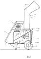
- the shredding device has a housing with an upper part 1 and a lower part 2.
- the upper part 1 is provided in the rear part with a main funnel 3, while in the front part a cover plate 4 forms an outlet channel for the comminuted material.
- a drive motor 5 is arranged on a horizontal section of the upper part 1 on a slide 6 which can be displaced in the horizontal direction (see arrows).
- the lower part 2 is provided with legs 7 in the front area and with wheels 8 in the rear area.
- a horizontal drive shaft 9 with a V-belt pulley 10 is inserted through the lower part 2 and is in drive connection with the drive motor 5 via a V-belt 12 with a V-belt pulley 11.
- a mudguard cover 13 is pushed over the two V-belt pulleys 10 and 11 and the V-belt 12.
- a side funnel 14 is also arranged laterally on the lower part 2 and communicates with the interior of the lower part 2 via an opening 15 in the side wall arranged on this side.
- the side funnel 14 is detachably connected to the lower part 2, for which purpose it can be inserted into side rails from above which are arranged on the side wall of the lower part 2.
- An elongated nose or bar 17 on the upper wall of the side funnel 14 rests on it and is positioned exactly.
- a disk 18 is arranged on the drive shaft 9 in the housing in front of the opening 15 and is provided with knife-like members.
- In a known manner on the drive shaft 9 there are a plurality of transverse bolts 19 distributed over the circumference between the disk 18 and others Disks 20 and 21 arranged.
- Hammer-like comminution members 22 are pivotally arranged on the cross bolts 19 next to one another and at a distance from one another, which are effective during the rotation of the drive shaft 9 due to the centrifugal effect.
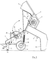
- a horizontal pivot axis 23 is mounted in the lower part 2 behind the main funnel 3.
- the upper part 1 is also pivotally connected to the pivot axis 23.
- the connection is in the form of a hinge, as a result of which the upper part 1 can be pivoted or folded about the axis of the pivot axis 23.
- the upper part 1 can be folded backwards and away from the lower part 2, namely until the main funnel 3 lies with one of its filling edges on the floor. This ensures a safe and stable position when opened.
- upper part 1 and lower part 2 are connected to one another by one or more bolts 24 which are pushed horizontally through the housing and are correspondingly pushed through bores which are located in the side walls of upper part 1 and lower part 2 which overlap in this area are located.
- the bolts are also the locking bolts for one or more gratings 25 and 26 arranged in front of the outlet duct 4.
- a tension spring 27 is stretched laterally on the back between the upper part 1 and the lower part 2.
- the lower ends of the two tension springs 27 are tensioned in the lower part 2 in a U-rail via bolts 28 inserted through bores in the U-legs. Through several bores lying one above the other, the tension of the tension springs 27 can be changed if necessary by appropriately moving the bolts 28.
- the two tension springs 27 are each articulated to the upper part 1 via a pivot lever 29.
- the purpose of the two tension springs 27 is to ensure that the upper part 1 and lower part 2 are securely folded apart, in particular to prevent the lower part 2 from slipping or folding away. This danger is in fact present when a heavy-duty drive motor 5 possibly together with the Upper part 1 is pivoted. Since the drive motor 5 changes its center of gravity during the pivoting movement, the lower part 2 could suddenly suddenly fold away or slip away without the tension springs 27.
- the carriage 6 with the drive motor located on it is displaced in the horizontal direction in a first step until the V-belt 12 is relaxed so much in a second step that it can be removed, for which purpose the mudguard cover 13 has to be assumed beforehand .
- the side funnel 14 is pushed upward out of its side guide rails 16 and thus detached from the lower part 2 if it is perceived as disturbing. If necessary, it can also remain on the lower part 2.
- a fourth step bolts 24 are pulled out horizontally.
- the securing for the bolts or as a quick release for this can e.g. Serve pins (not shown) that secure the bolts 24 in the operating position and which are then pulled out.
- Fig. 3 which shows the opened state, the bores 30 are visible in a side wall of the upper part 1, through which bolts 24 are inserted in the operating position.
- the upper part 1 can be pivoted about the pivot axis 23, as a result of which access into the interior of the housing, in particular the knife-like cutting members and the hammer-like crushing members and the grating or gratings 25 and 26, is possible.
- the comminuting device After maintenance, cleaning or elimination of the malfunctions that have occurred, the comminuting device can be reassembled in the reverse order.
- the opening 15 is to be covered with a slide for safety reasons.
- a suspension device e.g. Provide in the form of a hook 31 on which, when the side funnel 14 is not used, it can be arranged under a filler neck 32 of the main funnel 3 in a non-disturbing manner. With an edge of the filler neck 32, the upper part 1 also sits securely on the floor in the folded state (see FIG. 3).
Abstract
Description
Die Erfindung betrifft eine Zerkleinerungsvorrichtung, insbesondere für Gartenabfall, mit einem Gehäuse, das mit einem Haupttrichter zur Zugabe von zu zerkleinerndem Gut und gegebenenfalls mit einem Seitentrichter zum Einfüllen und zum Schneiden von gröberen Teilen versehen ist, mit hammerartigen Zerkleinerungsgliedern und/oder messerartigen Schneidegliedern, mit einer Antriebseinrichtung für die Zerkleinerungs- und/oder Schneideglieder und mit einem Auslaßkanal für das zerkleinerte Gut.The invention relates to a shredding device, in particular for garden waste, with a housing which is provided with a main hopper for adding material to be shredded and optionally with a side hopper for filling and cutting coarser parts, with hammer-like shredding members and / or knife-like cutting members a drive device for the comminution and / or cutting members and with an outlet channel for the comminuted material.
Zerkleinerungsvorrichtungen dieser Art werden auch als Schredder, Häcksler oder Hammermühlen bezeichnet. Sie dienen zum Zerkleinern und/oder Zerschneiden von Gartenabfällen, wie z.B. Zweige, Äste und anderem Gartenabfall. Sehr häufig werden derartige Vorrichtungen auch für Kompostierungsanlagen verwendet.Shredding devices of this type are also referred to as shredders, choppers or hammer mills. They are used to shred and / or cut garden waste, e.g. Twigs, branches and other garden waste. Such devices are also very often used for composting plants.
Bekannte Zerkleinerungsvorrichtungen dieser Art besitzen den Nachteil, daß sie nur schwer zerlegbar sind bzw. bei Auftreten von Störungen und/oder zu Wartungszwecken eine aufwendige und umständliche Demontage vorgenommen werden muß. Insbesondere bei einem Auftreten von Verstopfungen im Betrieb ist deren Beseitigung mühsam und zeitraubend.Known shredding devices of this type have the disadvantage that they are difficult to disassemble or, in the event of malfunctions and / or for maintenance purposes, an expensive and complicated disassembly has to be carried out. In particular, when blockages occur in operation, their removal is tedious and time-consuming.
Der vorliegenden Erfindung liegt die Aufgabe zugrunde eine Zerkleinerungsvorrichtung der eingangs erwähnten Art zu schaffen, die bei einfachem und kompaktem Aufbau sehr wartungsfreundlich ist, insbesondere wobei bei Auftreten von Verstopfungen oder anderen Betriebsstörungen diese auf einfache Weise und sehr schnell beseitigt werden können. Darüber hinaus soll die Zerkleinerungsvorrichtung unfallsicher und betriebssicher sein.The present invention has for its object to provide a crushing device of the type mentioned, which is very easy to maintain with a simple and compact structure, in particular when blockages or other malfunctions occur can be removed easily and very quickly. In addition, the shredding device should be accident-proof and operationally safe.
Erindungsgemäß wird diese Aufgabe durch die im kennzeichnenden Teil von Anspruch 1 genannten Merkmale gelöst.According to the invention, this task is characterized by Part of
Durch die erfindungsgemäße Aufteilung des Gehäuses in ein Oberteil und ein Unterteil und durch deren Verschwenkbarkeit zueinander wird eine leichte und schnelle Zugänglichkeit in das Innere der Vorrichtung geschaffen. Hierzu ist es lediglich erforderlich, daß die für den Betrieb vorgesehenen und erforderlichen Verbindungsglieder leicht lösbar bzw. entfernbar sind. Dies kann z.B. auf einfache Weise durch entsprechende Schraub-, Bolzen- oder Stiftverbindungen mit Schnellverschlüssen erfolgen.The inventive division of the housing into an upper part and a lower part and the fact that they can be pivoted relative to one another provides easy and quick access to the interior of the device. All that is required for this is that the connecting links provided and required for operation are easily detachable or removable. This can e.g. in a simple manner by means of appropriate screw, bolt or pin connections with quick-release fasteners.
Kommt es während des Betriebes der erfindungsgemäßen Zerkleinerungsvorrichtung zu irgendwelchen Störungen, insbesondere zu Verstopfungen, so lassen sich diese durch ein einfaches Abschwenken des Oberteiles beseitigen, denn danach ist das Innere der Vorrichtung mit den Zerkleinerungs- und/oder Schneidegliedern offen zugänglich.If there are any malfunctions, in particular blockages, during operation of the comminuting device according to the invention, these can be removed by simply swiveling the upper part away, since the interior of the apparatus with the comminuting and / or cutting members is then openly accessible.
Vorteilhafte Weiterbildungen und Ausgestaltungen der Erfindung ergeben sich aus den Unteransprüchen und aus dem nachfolgend anhand der Zeichnung prinzipmäßig beschriebenen Ausführungsbeispiel.Advantageous further developments and refinements of the invention result from the subclaims and from the exemplary embodiment described in principle below with reference to the drawing.
Es zeigt:
- Fig. 1
- eine Seitenansicht der erfindungsgemäßen Zerkleinerungsvorrichtung;
- Fig. 2
- eine Stirnansicht der erfindungsgemäßen Zerkleinerungsvorrichtung nach der Fig. 1 (zur besseren Übersicht ohne Zugfedern);
- Fig. 3
- eine Seitenansicht der Zerkleinerungsvorrichtung nach den Fig. 1 und 2 mit einem abgeschwenkten Oberteil.
- Fig. 1
- a side view of the shredding device according to the invention;
- Fig. 2
- a front view of the shredding device according to the invention of Figure 1 (for a better overview without tension springs).
- Fig. 3
- a side view of the shredding device according to FIGS. 1 and 2 with a pivoted upper part.
Grundsätzlich ist die Zerkleinerungsvorrichtung von bekanntem Aufbau, weshalb nachfolgend nur die für die Erfindung wesentlichen Teile näher beschrieben werden.Basically, the shredding device is of known construction, which is why only the parts essential to the invention are described in more detail below.
Die Zerkleinerungsvorrichtung weist ein Gehäuse mit einem Oberteil 1 und einem Unterteil 2 auf. Das Oberteil 1 ist im hinteren Teil mit einem Haupttrichter 3 versehen, während im vorderen Teil ein Abdeckblech 4 einen Auslaßkanal für das zerkleinerte Gut bildet. Auf einem horizontalen Abschnitt des Oberteiles 1 ist ein Antriebsmotor 5 auf einem in horizontaler Richtung verschiebbaren Schlitten 6 (siehe Pfeile) angeordnet.The shredding device has a housing with an
Das Unterteil 2 ist im vorderen Bereich mit Standbeinen 7 und im hinteren Bereich mit Rädern 8 versehen. Durch das Unterteil 2 ist eine horizontale Antriebswelle 9 mit einer Keilriemenscheibe 10 gesteckt, die mit einer Keilriemenscheibe 11 über einen Keilriemen 12 in Antriebsverbindung mit dem Antriebsmotor 5 steht. Aus Sicherheitsgründen ist über die beiden Keilriemenscheiben 10 und 11 und den Keilriemen 12 eine Schutzblechabdeckung 13 geschoben.The
Seitlich am Unterteil 2 ist noch ein Seitentrichter 14 angeordnet, der über eine Öffnung 15 in der auf dieser Seite angeordneten Seitenwand mit dem Innenraum des Unterteiles 2 in Verbindung steht. Der Seitentrichter 14 ist lösbar mit dem Unterteil 2 verbunden, wozu er in seitliche Schienen von oben her einschiebbar ist, die an der Seitenwand des Unterteiles 2 angeordnet sind. Durch eine verlängerte Nase oder Leiste 17 an der oberen Wand des Seitentrichters 14 liegt dieser auf und ist exakt positioniert. Innenseitig ist in dem Gehäuse vor der Öffnung 15 eine Scheibe 18 auf der Antriebswelle 9 angeordnet, die mit messerartigen Gliedern versehen ist. Auf der Antriebswelle 9 sind in bekannter Weise mehrere über den Umfang verteilt angeordnete Querbolzen 19 zwischen der Scheibe 18 und weiteren Scheiben 20 und 21 angeordnet. Auf den Querbolzen 19 sind nebeneinander und auf Abstand voneinander hammerartige Zerkleinerungsglieder 22 schwenkbar angeordnet, die während der Rotation der Antriebswelle 9 durch die Zentrifugalwirkung wirksam werden.A
Hinter dem Haupttrichter 3 ist in dem Unterteil 2 eine horizontale Schwenkachse 23 gelagert. Mit der Schwenkachse 23 ist auch das Oberteil 1 schwenkbar verbunden. Die Verbindung ist in Form eines Scharnieres gegeben, wodurch das Oberteil 1 um die Achse der Schwenkachse 23 schwenkbar bzw. klappbar ist.A
Wie aus der Fig. 3 ersichtlich ist, läßt sich auf diese Weise das Oberteil 1 nach hinten und von dem Unterteil 2 wegklappen, und zwar so weit, bis der Haupttrichter 3 mit einer seinen Einfüllkanten auf dem Boden aufliegt. Auf diese Weise ist eine sichere und stabile Lage im aufgeklappten Zustand sichergestellt.As can be seen from FIG. 3, in this way the
Im Betriebszustand sind Oberteil 1 und Unterteil 2 durch ein oder mehrere horizontal durch das Gehäuse geschobene Bolzen 24 miteinander verbunden, die entsprechend durch Bohrungen durchgeschoben sind, die sich in den seitlichen, sich in diesem Bereich überlappenden Seitenwänden von Oberteil 1 und Unterteil 2 befinden.In the operating state,
In vorteilhafter Weise sind die Bolzen gleichzeitig auch die Arretierungsbolzen für ein oder mehrere vor dem Auslaßkanal 4 angeordnete Gitterroste 25 und 26.Advantageously, the bolts are also the locking bolts for one or
Wie aus den Fig. 1 und 3 ersichtlich ist, ist rückseitig jeweils seitlich eine Zugfeder 27 zwischen das Oberteil 1 und das Unterteil 2 gespannt. Die unteren Enden der beiden Zugfedern 27 sind dabei im Unterteil 2 in einer U-Schiene über durch Bohrungen in den U-Schenkeln gesteckte Bolzen 28 gespannt. Durch mehrere übereinander liegende Bohrungen läßt sich im Bedarfsfalle durch entsprechendes Versetzen der Bolzen 28 die Zugspannung der Zugfedern 27 ändern.As can be seen from FIGS. 1 and 3, a
Am anderen Ende sind die beiden Zugfedern 27 jeweils über einen Schwenkhebel 29 gelenkig mit dem Oberteil 1 verbunden.At the other end, the two
Die beiden Zugfedern 27 haben den Zweck, ein sicheres Auseinanderklappen von Oberteil 1 und Unterteil 2 zu gewährleisten, insbesondere ein unerwünschtes Wegrutschen oder Wegklappen des Unterteiles 2 zu vermeiden. Diese Gefahr ist nämlich gegeben, wenn ein schwergewichtiger Antriebsmotor 5 eventuell zusammen mit dem Oberteil 1 verschwenkt wird. Da der Antriebsmotor 5 während der Schwenkbewegung seinen Schwerpunkt ändert, könnte ohne die Zugfedern 27 eventuell plötzlich das Unterteil 2 ruckartig wegklappen oder wegrutschen.The purpose of the two
Um zu Wartungs- oder Reparaturzwecken oder um Verstopfungen zu vermeiden in das Innere der Vorrichtung zu gelangen, sind lediglich folgende Handgriffe erforderlich:In order to get inside the device for maintenance or repair purposes or to avoid blockages, only the following steps are required:
Durch eine nicht näher dargestellte Verschiebeeinrichtung, z.B. einen Verschwenkhebel, wird in einem ersten Schritt der Schlitten 6 mit dem darauf sich befindenden Antriebsmotor in horizontaler Richtung so weit verschoben, bis in einem zweiten Schritt der Keilriemen 12 so weit entspannt wird, daß er abgenommen werden kann, wozu vorher die Schutzblechabdeckung 13 anzunehmen ist.By a shifting device, not shown, e.g. a pivoting lever, the
In einem dritten Schritt wird - sofern bei der Vorrichtung vorhanden - der Seitentrichter 14 nach oben aus seinen seitlichen Führungsschienen 16 herausgeschoben und damit von dem Unterteil 2 gelöst, wenn er als störend empfunden wird. Gegebenenfalls kann er auch am Unterteil 2 verbleiben.In a third step, if the device is present, the
In einem vierten Schritt wird bzw. werden Bolzen 24 horizontal herausgezogen. Die Sicherung für die Bolzen bzw. als Schnellverschluß hierfür können z.B. Splinte (nicht dargestellt) dienen, die die Bolzen 24 in Betriebsstellung sichern und die dann herausgezogen werden. In der Fig. 3, die den aufgeklappten Zustand zeigt, sind die Bohrungen 30 in einer Seitenwand des Oberteiles 1 sichtbar, durch die Bolzen 24 in Betriebsstellung gesteckt sind.In a fourth step,
Nach diesen geringen Vorarbeiten läßt sich das Oberteil 1 um die Schwenkachse 23 verschwenken, wodurch ein Zugang in das Innere des Gehäuses, insbesondere den messerartigen Schneidegliedern und den hammerartigen Zerkleinerungsgliedern und dem oder den Gitterrosten 25 und 26 möglich ist.After this little preliminary work, the
Nach einer Wartung, Reinigung oder Beseitigung der aufgetretenen Störungen läßt sich in umgekehrter Reihenfolge die Zerkleinerungsvorrichtung wieder zusammensetzen.After maintenance, cleaning or elimination of the malfunctions that have occurred, the comminuting device can be reassembled in the reverse order.
Wird ein Betrieb der Zerkleinerungsvorrichtung ohne den Seitentrichter 14 gewünscht, so ist aus Sicherheitsgründen die Öffnung 15 mit einem Schieber abzudecken. Dabei wird man im allgemeinen eine derartige Kontaktverbindung zu dem Antriebsmotor vorsehen, daß dessen Betrieb nur möglich ist, wenn die Öffnung 15 entweder durch den Seitentrichter 14 oder durch den Schieber abgedeckt ist.If operation of the shredding device without the
In vorteilhafter Weise wird man außenseitig an dem Haupttrichter 3 eine Aufhängeeinrichtung, z.B. in Form eines Hakens 31 vorsehen, an dem bei Nichtverwendung des Seitentrichter 14 dieser damit in nicht störender Weise unter einem Einfüllstutzen 32 des Haupttrichters 3 angeordnet werden kann. Mit einer Kante des Einfüllstutzens 32 sitzt das Oberteil 1 im abgeklappten Zustand auch sicher auf dem Boden auf (siehe Fig. 3).In an advantageous manner, a suspension device, e.g. Provide in the form of a
Claims (12)
dadurch gekennzeichnet, daß das Gehäuse in ein Unterteil (2), in dem wenigsten die Zerkleinerungs- und/oder Schneideglieder (22) angeordnet sind, und ein Oberteil (1) aufgeteilt ist, wobei Oberteil (1) und Unterteil (2) lösbar miteinander verbunden sind und das Oberteil (1) für einen freien Zugang in das Innere der Zerkleinerungsvorrichtung von dem Unterteil (2) wegschwenkbar ist.Shredding device, in particular for garden waste, with a housing which is provided with a main hopper for adding material to be shredded and, if appropriate, with a side hopper for filling and cutting coarser parts, with hammer-like shredding members and / or knife-like cutting members, with a drive device for the Shredding and / or cutting links and with an outlet channel for the shredded material,
characterized in that the housing in a lower part (2), in the least the crushing and / or cutting links (22) are arranged, and an upper part (1) is divided, the upper part (1) and lower part (2) being detachably connected to one another and the upper part (1) for free access to the inside of the Shredding device can be pivoted away from the lower part (2).
dadurch gekennzeichnet, daß auf dem Oberteil (1) wenigstens der Antriebsmotor (5) und der Haupttrichter (3) angeordnet sind.Comminution device according to claim 1,
characterized in that at least the drive motor (5) and the main funnel (3) are arranged on the upper part (1).
dadurch gekennzeichnet, daß zur Verschwenkung eine Schwenkachse (23) vorgesehen ist, die sich im unteren Bereich außenseitig hinter dem Haupttrichter befindet.Comminution device according to claim 1 or 2,
characterized in that a pivot axis (23) is provided for pivoting and is located in the lower region on the outside behind the main funnel.
dadurch gekennzeichnet, daß zwischen dem Oberteil (1) und dem Unterteil (2) auf der Seite des Gehäuses, auf der Oberteil (1) und Unterteil (2) schwenkbar miteinander verbunden sind, ein oder mehrere Zugfedern (27) zwischen Oberteil (1) und Unterteil (2) gespannt sind.Comminution device according to claim 1, 2 or 3,
characterized in that between the upper part (1) and the lower part (2) on the side of the housing, on the upper part (1) and lower part (2) are pivotally connected to one another, one or more tension springs (27) between Upper part (1) and lower part (2) are tensioned.
dadurch gekennzeichnet, daß die Zugfedern (27) außenseitig mit ihren einen Enden jeweils an einer Lagerstelle im unteren Bereich des Unterteiles (2) eingespannt sind, während die anderen Enden gelenkig über Schwenkhebel (29) mit dem Oberteil (1) verbunden sind.Comminution device according to claim 4,
characterized in that the tension springs (27) are clamped on the outside with their one ends in each case at a bearing point in the lower region of the lower part (2), while the other ends are articulatedly connected to the upper part (1) via swivel levers (29).
dadurch gekennzeichnet, daß die lösbare Verbindung zwischen Oberteil (1) und Unterteil (2) durch Stifte, Bolzen oder dergleichen (24) erfolgt, die im Betriebszustand auf der von der Schwenkachse abgewandten Seite Oberteil (1) und Unterteil (2) miteinander verbinden.Comminution device according to one of claims 1 to 5,
characterized in that the releasable connection between the upper part (1) and lower part (2) is made by pins, bolts or the like (24) which, in the operating state, connect the upper part (1) and lower part (2) to one another on the side facing away from the pivot axis.
dadurch gekennzeichnet, daß die Stifte, Bolzen oder dergleichen (24) eine Doppelfunktion derart besitzen, daß sie gleichzeitig als Arretierungsglied für ein Gitterrost (25,26) dienen.Comminution device according to claim 6,
characterized in that the pins, bolts or the like (24) have a double function in such a way that they simultaneously serve as a locking member for a grating (25, 26).
dadurch gekennzeichnet, daß der Seitentrichter (14) lösbar an dem Unterteil (2) befestigt ist.Comminution device according to one of claims 1 to 7,
characterized in that the side funnel (14) is detachably attached to the lower part (2).
dadurch gekennzeichnet, daß die Öffnung für den Seitentrichter (14) im Unterteil (2) bei abgenommenen Seitentrichter (14) durch einen Schieber abschließbar ist.Comminution device according to claim 8,
characterized in that the opening for the side funnel (14) in the lower part (2) with the side funnel (14) removed can be closed by a slide.
dadurch gekennzeichnet, daß der Seitentrichter (14) in seitlichen Führungen (16) in dem Unterteil (2) einschiebbar ist.Comminution device according to claim 8 or 9,
characterized in that the side funnel (14) can be inserted into lateral guides (16) in the lower part (2).
dadurch gekennzeichnet, daß der Seitentrichter (14) nach dessen Abnahme stirnseitig auf der Außenseite des Haupttrichters (3) befestigbar ist.Comminution device according to one of claims 8 to 10,
characterized in that the side funnel (14) can be fastened on the outside on the outside of the main funnel (3) after it has been removed.
dadurch gekennzeichnet, daß der Motor (5) der Antriebseinrichtung auf einem horizontal verschiebbaren Schlitten (6) angeordnet ist.Comminution device according to one of claims 1 to 11,
characterized in that the motor (5) of the drive device is arranged on a horizontally displaceable carriage (6).
Applications Claiming Priority (2)
| Application Number | Priority Date | Filing Date | Title |
|---|---|---|---|
| DE19924220245 DE4220245A1 (en) | 1992-06-20 | 1992-06-20 | Shredding device, in particular for garden waste |
| DE4220245 | 1992-06-20 |
Publications (1)
| Publication Number | Publication Date |
|---|---|
| EP0579923A1 true EP0579923A1 (en) | 1994-01-26 |
Family
ID=6461464
Family Applications (1)
| Application Number | Title | Priority Date | Filing Date |
|---|---|---|---|
| EP93108159A Withdrawn EP0579923A1 (en) | 1992-06-20 | 1993-05-19 | Shredding apparatus especially for garden refuse |
Country Status (3)
| Country | Link |
|---|---|
| EP (1) | EP0579923A1 (en) |
| CH (1) | CH681342A5 (en) |
| DE (1) | DE4220245A1 (en) |
Cited By (2)
| Publication number | Priority date | Publication date | Assignee | Title |
|---|---|---|---|---|
| CN106563548A (en) * | 2016-11-10 | 2017-04-19 | 无锡威格斯电气有限公司 | Micromill |
| CN107258250A (en) * | 2017-06-28 | 2017-10-20 | 徐州市沅和牧业有限责任公司 | A kind of forage wire kneading machine of wide adaptation range |
Families Citing this family (3)
| Publication number | Priority date | Publication date | Assignee | Title |
|---|---|---|---|---|
| DE4409446C2 (en) * | 1994-03-19 | 1996-01-11 | Neudorff W Gmbh Kg | Rotationally symmetrical planing head and shredding device |
| US6102312A (en) * | 1999-06-17 | 2000-08-15 | Aberle; David H. | Rotary hammer mill |
| DE102015011437A1 (en) * | 2015-09-01 | 2017-03-02 | Julius Tielbürger GmbH & Co. KG | Garden shredder with a chassis |
Citations (4)
| Publication number | Priority date | Publication date | Assignee | Title |
|---|---|---|---|---|
| FR1548895A (en) * | 1966-12-23 | 1968-12-06 | ||
| US3907216A (en) * | 1973-03-26 | 1975-09-23 | Amerind Mackissic Inc | Disintegration apparatus |
| DE8907251U1 (en) * | 1989-06-14 | 1989-08-03 | Maschinen- Und Landmaschinenfabrik Husmann Gmbh, 4474 Lathen, De | |
| EP0389249A1 (en) * | 1989-03-21 | 1990-09-26 | Schiller-Pfeiffer, Inc. | Combination leaf and lawn debris comminuting vacuum and wood chipper |
-
1992
- 1992-06-20 DE DE19924220245 patent/DE4220245A1/en not_active Withdrawn
- 1992-08-21 CH CH260592A patent/CH681342A5/de not_active IP Right Cessation
-
1993
- 1993-05-19 EP EP93108159A patent/EP0579923A1/en not_active Withdrawn
Patent Citations (4)
| Publication number | Priority date | Publication date | Assignee | Title |
|---|---|---|---|---|
| FR1548895A (en) * | 1966-12-23 | 1968-12-06 | ||
| US3907216A (en) * | 1973-03-26 | 1975-09-23 | Amerind Mackissic Inc | Disintegration apparatus |
| EP0389249A1 (en) * | 1989-03-21 | 1990-09-26 | Schiller-Pfeiffer, Inc. | Combination leaf and lawn debris comminuting vacuum and wood chipper |
| DE8907251U1 (en) * | 1989-06-14 | 1989-08-03 | Maschinen- Und Landmaschinenfabrik Husmann Gmbh, 4474 Lathen, De |
Cited By (2)
| Publication number | Priority date | Publication date | Assignee | Title |
|---|---|---|---|---|
| CN106563548A (en) * | 2016-11-10 | 2017-04-19 | 无锡威格斯电气有限公司 | Micromill |
| CN107258250A (en) * | 2017-06-28 | 2017-10-20 | 徐州市沅和牧业有限责任公司 | A kind of forage wire kneading machine of wide adaptation range |
Also Published As
| Publication number | Publication date |
|---|---|
| CH681342A5 (en) | 1993-03-15 |
| DE4220245A1 (en) | 1993-12-23 |
Similar Documents
| Publication | Publication Date | Title |
|---|---|---|
| EP3248687B1 (en) | Two-shaft shredder having quick change device | |
| EP2012927A1 (en) | Comminuting device | |
| DE3807983C2 (en) | Crushing device | |
| EP1442796B1 (en) | Comminuting device | |
| EP0832554B1 (en) | Combine | |
| EP0674983A1 (en) | Granulator device for filamentary material | |
| EP2065091B1 (en) | Material grinder | |
| DE4000887A1 (en) | Rotor for machine for cutting up scrap wood - incorporates circular blades fixed to rotor periphery | |
| AT523406B1 (en) | Shredding machine | |
| EP0579923A1 (en) | Shredding apparatus especially for garden refuse | |
| DE4315671C2 (en) | Shredding machine for solids with paired rotating cutter blades | |
| DE19713264C1 (en) | Hammer mill or crusher | |
| DE102010050786B3 (en) | Discharge device for a wood chipper | |
| EP0015877A1 (en) | Device for shredding refuse and method for operating this device | |
| EP2708340B1 (en) | Device for screening wood chips | |
| WO1998028078A1 (en) | Chopper with a fixing device | |
| DE10026825C2 (en) | comminution device | |
| DE102012006650A1 (en) | Crushing device for dividing bulky waste material, particularly wood and plastic waste, into manageable pieces, has feeding unit and part of storage container, which are connected to pivot machine unit | |
| DE2947510C2 (en) | ||
| CH415334A (en) | Shredding machine for meat or other food and luxury foods that can be shredded | |
| DE3211137A1 (en) | Comminution device | |
| DE3123484C2 (en) | Shredding device for fibrous material | |
| DE2347354A1 (en) | Food mincing and shredding machine - has cutter and pressure rolls supported on swivelling halves of split housing | |
| DE19706425C1 (en) | Laboratory grinding mill | |
| EP4062736A1 (en) | Agricultural spreading device |
Legal Events
| Date | Code | Title | Description |
|---|---|---|---|
| PUAI | Public reference made under article 153(3) epc to a published international application that has entered the european phase |
Free format text: ORIGINAL CODE: 0009012 |
|
| AK | Designated contracting states |
Kind code of ref document: A1 Designated state(s): AT DE FR GB IT NL |
|
| 17P | Request for examination filed |
Effective date: 19940308 |
|
| 17Q | First examination report despatched |
Effective date: 19950620 |
|
| STAA | Information on the status of an ep patent application or granted ep patent |
Free format text: STATUS: THE APPLICATION IS DEEMED TO BE WITHDRAWN |
|
| 18D | Application deemed to be withdrawn |
Effective date: 19960103 |