EP0577874A1 - Ondulateur comportant des agencements de bobines concentriques - Google Patents
Ondulateur comportant des agencements de bobines concentriques Download PDFInfo
- Publication number
- EP0577874A1 EP0577874A1 EP92111569A EP92111569A EP0577874A1 EP 0577874 A1 EP0577874 A1 EP 0577874A1 EP 92111569 A EP92111569 A EP 92111569A EP 92111569 A EP92111569 A EP 92111569A EP 0577874 A1 EP0577874 A1 EP 0577874A1
- Authority
- EP
- European Patent Office
- Prior art keywords
- coil
- wiggler
- coils
- vertical axis
- tesla
- Prior art date
- Legal status (The legal status is an assumption and is not a legal conclusion. Google has not performed a legal analysis and makes no representation as to the accuracy of the status listed.)
- Withdrawn
Links
Images


Classifications
-
- H—ELECTRICITY
- H05—ELECTRIC TECHNIQUES NOT OTHERWISE PROVIDED FOR
- H05H—PLASMA TECHNIQUE; PRODUCTION OF ACCELERATED ELECTRICALLY-CHARGED PARTICLES OR OF NEUTRONS; PRODUCTION OR ACCELERATION OF NEUTRAL MOLECULAR OR ATOMIC BEAMS
- H05H7/00—Details of devices of the types covered by groups H05H9/00, H05H11/00, H05H13/00
- H05H7/04—Magnet systems, e.g. undulators, wigglers; Energisation thereof
Definitions
- the invention relates to a wiggler with a longitudinal axis and a vertical axis intersecting it and perpendicular to it, with two coil arrangements which are spaced apart from one another along the vertical axis and are aligned essentially mirror-symmetrically to one another with respect to a central plane containing the longitudinal axis and perpendicular to the vertical axis, and each of which has one Has a plurality of substantially flat coils.
- the invention relates in particular to wigglers with superconducting coils and to wigglers which are intended to generate magnetic fields whose maxima are between 2 Tesla and 10 Tesla, in particular around 4 Tesla to 5 Tesla.
- Such wigglers are used in accelerator systems and storage ring systems for elementary particles, especially electrons and / or positrons, to generate synchrotron radiation.
- Wiggler can also be used for various control and regulation applications.
- a wiggler is basically a device that generates a magnetic field, which is distinguished in that it deflects a charged elementary particle that has entered the magnetic field along a predetermined, generally rectilinear target path from this target path and returns it to it, so that the elementary particle applies the magnetic field leaves the target path.
- the effect the wiggler on an elementary particle flying through is limited in this sense to a certain time delay, since the particle flies through a curved path inside the wiggler which is longer than the nominal path; behind the wiggler the elementary particle flies again on the target orbit, on which it would also fly in the absence of the wiggler.
- Wigglers are particularly interesting since they allow the generation of synchrotron radiation independently of deflection magnets and the like;
- an existing accelerator or storage ring system which due to its spatial arrangement and / or the dimensions of its deflecting magnets is not or only partially suitable for the efficient generation of synchrotron radiation, can be supplemented by retrofitting a wiggler to a high-quality synchrotron radiation source.
- the path of the elementary particle in the magnetic field is curved several times, so that synchrotron radiation is emitted on several sections of the path.
- the first-mentioned document relates to a wiggler with superconducting coils, which generates a maximum magnetic field of about 5 Tesla; the second document provides an overview of the entire technical environment of wigglers and undulators; In particular, reference is hereby expressly made to this document and its entire disclosure.
- superconducting coils in wigglers have so-called "racetrack shapes" (a single coil can have concentric and / or superposed partial coils, depending on the application).
- a wiggler is formed from two coil arrangements arranged mirror-symmetrically to one another with respect to a central plane, each of which consists of a plurality of coils arranged alongside one another along a longitudinal axis in the central plane, in the form of a racetrack.
- these coils are subjected to electrical currents in certain proportions and in predetermined directions of rotation and thus generate a spatially varying magnetic field along the longitudinal axis, which is also the desired path of the elementary particles passing through the Wiggler, which detects the elementary particles entering along the longitudinal axis in a certain way deflects a more or less complicated, multi-curved path and finally leads it back to the target path. Details of this can be found in the documents of the prior art.
- the curved segments of these coils create the magnetic field on the Do not significantly affect the longitudinal axis; therefore, very elongated coils usually have to be used.
- the present invention is based on the following task:
- the dimensions of the wiggler which have so far been considerable for the reasons mentioned above, are to be significantly reduced, moreover, coils with simple, easy-to-produce shapes should be usable, and finally the forces exerted between the coils and by the coils on their holding structures should be reduced as far as possible.
- the Wiggler according to the invention with a longitudinal axis and a vertical axis intersecting it and perpendicular to this, which Wiggler has two coil arrangements which are spaced apart from one another along the vertical axis and are aligned essentially mirror-symmetrically to one another with respect to a central plane containing the longitudinal axis and perpendicular to the vertical axis, and each of which has one
- a plurality of essentially flat coils is characterized in that each coil arrangement has an inner coil which is axially symmetrical with respect to the vertical axis and an outer coil which is axially symmetrical with respect to the vertical axis, which surrounds the inner coil.
- the invention is based on the knowledge that magnetic fields of the type required in Wiggemper can be generated not only with the known coil arrangements from three race track coils arranged next to one another, but also with arrangements from two coils which are concentric with one another.
- the generation of a magnetic field with coil arrangements from two coils is made possible, which previously required coil arrangements with three coils. Since racetrack coils, in particular relatively elongated racetrack coils, are difficult to manufacture, a remarkable advantage is achieved with the invention. Even if a racing track coil is still required as the inner coil, a coil with a simpler shape can be used as the outer coil; the advantage also results from the smaller curvatures that are present in the outer coil, which must have a larger diameter than the inner coil.
- the coil arrangements according to the invention With the coil arrangements according to the invention, a significant simplification of the cryosystem is also possible, which is required in the case of a superconducting wiggler to cool the coils to sufficiently low temperatures; while ensuring a relatively compact design, the coil arrangement according to the invention can be implemented in a much more space-saving manner than the previously known coil arrangements and thereby leaves considerably more space for cryogenic devices and supports and the like than the coil arrangements of the prior art.
- the outer coil is given an approximately circular symmetry, that is to say a round shape. Such a shape is particularly easy to manufacture, which requires no further explanation at this point.
- the inner coil in the Wiggler according to the invention is in particular a coil which is stretched along a transverse axis which is perpendicular to the longitudinal axis and perpendicular to the vertical axis.
- an inner coil in the form of a racetrack can be used; however, it should be noted that the invention uses Racetrack spools are permitted that are significantly less stretched than previously required racetrack coils.
- a first effect is the increase in the field at the center of the Coil arrangement, since the curved segments of the racetrack coils make increased contributions by shortening the straight segments; a second effect is a spatially stronger variation of the magnetic field in the vicinity of the center.
- a particularly advantageous embodiment of the wiggler which can possibly be added to other configurations, is that in each coil arrangement the coils are each at an associated distance from the center plane and the distance between the inner coil is smaller than the distance between the outer coil.
- the distances of the inner coils from the central plane essentially determine the height of the magnetic field generated in the center of the wiggler; these distances are therefore usually specified.
- the ratio between its distance from the longitudinal axis and its diameter must be kept sufficiently small for each coil, since otherwise irregularities occur in the magnetic field on the longitudinal axis, which are generally unacceptable.
- the outer coils have large diameters, they can also be arranged at greater distances from the central plane without significant losses; this simplifies the interpretation of the Cooling such superconducting coils required cryogenic systems quite considerably.
- each coil arrangement at least one coil is assigned an essentially flat compensating coil, which is aligned essentially axially symmetrically with respect to the vertical axis and approximately parallel to the central plane, wherein the coil lies between the center plane and the associated compensating coil.
- a compensating coil can be used to reduce the magnetic forces between two corresponding coils of the coil arrangements; the force that occurs between one coil and the associated compensating coil reduces the force between the coil and the corresponding coil in the other coil arrangement.
- Support devices arranged directly between corresponding coils of different coil arrangements can be dispensed with.
- the coils corresponding to one another can thus be brought closer to one another than previously, which is both a general improvement in the quality of the magnetic field generated and a significant increase in the strength of the magnetic field enables.
- the inner coils of the wiggler are particularly preferred for assigning compensating coils, since they are exposed to the greatest mechanical loads. It is understood that the magnetic fields of the compensating coils influence the magnetic fields of the inner coils and amplify them, which of course has to be taken into account when designing the inner coils and compensating coils; the same applies to the case that other coils are assigned compensation coils.
- a wiggler with a longitudinal axis and a vertical axis intersecting it and perpendicular to this, which wiggler has two coil arrangements which are spaced apart along the vertical axis and are essentially mirror-symmetrical to one another with respect to a central plane containing the longitudinal axis and perpendicular to the vertical axis, and each of which has a plurality of substantially planar coils, which Wiggler is further characterized in that in each coil arrangement at least one coil is assigned a substantially planar compensating coil which is oriented approximately concentrically to the coil and approximately parallel to the central plane, the coil between the central plane and the associated compensation coil, allows the laying of the necessary mechanical support devices from the space between corresponding coils of different coil arrangements to the respective spaces between the coils and their respective associated compensating coils, thus generally enables a particularly compact structure and, due to the smaller spacings of the corresponding coils, a significant improvement in the quality of the magnetic field generated.
- each compensating coil has approximately the same shape as the coil to which it is assigned; this feature allows a simplified production, since special facilities and expenses for the production of the compensation coils are not required.
- the wiggler according to the invention is particularly advantageously designed with superconducting coils; in particular, it also allows the coils to be designed to generate a magnetic field at the intersection of the longitudinal axis and the vertical axis, the center point of the wiggler, between 2 Tesla and 10 Tesla, in particular between 3 Tesla and 6 Tesla, preferably between 4 Tesla and 5 Tesla, which for many the usual applications is necessary.
- the wiggler according to the invention is particularly qualified in any training for generating synchrotron radiation by means of a beam of elementary particles, in particular electrons or positrons, which enters the wiggler along the longitudinal axis and likewise leaves it again along the longitudinal axis.
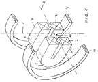
- FIG. 1 shows how two coil arrangements each of an inner coil 3 and an outer coil 4 form a wiggler according to the invention.
- Inner coils 3 and outer coils 4 are each flat and are aligned parallel to a central plane, which contains the longitudinal axis 1 and is aligned perpendicular to the vertical axis 2.
- the intersection 10 of the longitudinal axis 1 and the vertical axis 2 the magnetic field generated by the coils 3, 4 is strongest.
- each inner coil 3 has a so-called racetrack shape with two straight segments 7 which are connected to one another by two curved segments 6 (only one such curved segment 6 is visible for each inner coil 3).
- the outer coils 4 are approximately circular, which is why they are easy to manufacture.
- each coil arrangement between the respective inner coil 3 and the respective outer coil 4 there is a relatively large amount of space for mechanical support devices, cooling shields and the like, which is why the wiggler according to the invention can be made particularly compact.
- the inner coil 3 and the outer coil 4 are aligned essentially concentrically to one another, the centers of the coils 3, 4 lying on the vertical axis 2.
- the coil arrangements separated from one another by the central plane containing the longitudinal axis 1 are arranged mirror-symmetrically to one another with respect to the central plane.
- the mirror symmetry advantageously extends not only to the outer shape of the coils 3, 4, but also to the currents flowing in the coils 3, 4.
- FIG. 2 shows a vertical top view of a coil arrangement of the wiggler according to the invention.
- a circular outer coil 4 can be seen, in which a raceway-shaped inner coil 3 is arranged in a concentric manner.
- the longitudinal axis 1 indicates the direction of the elementary particles passing through the Wiggler.
- the inner coil 3 is stretched along a transverse axis 5 which, like the longitudinal axis 1, is parallel to the central plane.
- An advantage of the wiggler according to the invention is that inner coils 3 can be used which are only slightly stretched along the transverse axis 5; such coils are mechanically much more robust than strongly stretched coils, since a slightly stretched shape allows a much better compensation of the forces occurring parallel to the center plane between the straight segments 7 compared to strongly stretched coils.
- each inner coil 3 is assigned an approximately identical compensating coil 11, the inner coil 3 lying in each coil arrangement between the central plane given by the longitudinal axis 1 and the respective assigned compensating coil 11.
- the compensating coils 11 serve to compensate for the magnetic forces which the inner coils 3 exert on one another during operation.
- the magnetic fields of each inner coil 3 and the associated compensating coil 11 must be aligned parallel to one another.
- each inner coil 3 Due to the magnetic forces occurring between each inner coil 3 and the associated compensating coil 11, each inner coil 3 is drawn to its associated compensating coil 11; this reduces the force between the inner coils 3, which simplifies the mechanical support of the inner coils 3 against one another. Support material between the inner coils 3 can thus be dispensed with, the inner coils 3 can thus be brought closer to the central plane than before and it is on Intersection 10 between the longitudinal axis 1 and vertical axis 2 to achieve a higher magnetic field, corresponding to an improved synchrotron radiation generation.
- the wiggler according to the invention can be produced with comparatively little effort, it requires significantly less space than a wiggler according to the prior art, it offers the possibility of a significant simplification of the mechanical support devices which are still necessary and has a particularly high level of operational reliability.
Priority Applications (2)
| Application Number | Priority Date | Filing Date | Title |
|---|---|---|---|
| EP92111569A EP0577874A1 (fr) | 1992-07-08 | 1992-07-08 | Ondulateur comportant des agencements de bobines concentriques |
| PCT/EP1993/001767 WO1994001983A1 (fr) | 1992-07-08 | 1993-07-07 | Ondulateur comportant des agencements de bobines a bobines concentriques |
Applications Claiming Priority (1)
| Application Number | Priority Date | Filing Date | Title |
|---|---|---|---|
| EP92111569A EP0577874A1 (fr) | 1992-07-08 | 1992-07-08 | Ondulateur comportant des agencements de bobines concentriques |
Publications (1)
| Publication Number | Publication Date |
|---|---|
| EP0577874A1 true EP0577874A1 (fr) | 1994-01-12 |
Family
ID=8209794
Family Applications (1)
| Application Number | Title | Priority Date | Filing Date |
|---|---|---|---|
| EP92111569A Withdrawn EP0577874A1 (fr) | 1992-07-08 | 1992-07-08 | Ondulateur comportant des agencements de bobines concentriques |
Country Status (2)
| Country | Link |
|---|---|
| EP (1) | EP0577874A1 (fr) |
| WO (1) | WO1994001983A1 (fr) |
Cited By (1)
| Publication number | Priority date | Publication date | Assignee | Title |
|---|---|---|---|---|
| DE102006056052A1 (de) * | 2006-11-28 | 2008-05-29 | Forschungszentrum Karlsruhe Gmbh | Planar-helischer Undulator |
Families Citing this family (1)
| Publication number | Priority date | Publication date | Assignee | Title |
|---|---|---|---|---|
| GB2515446A (en) * | 2013-01-25 | 2014-12-31 | Europ Thermodynamics Ltd | Thermoelectric generators |
Citations (1)
| Publication number | Priority date | Publication date | Assignee | Title |
|---|---|---|---|---|
| DE2302979A1 (de) * | 1973-01-22 | 1974-07-25 | Siemens Ag | Wechselstrommagnet |
Family Cites Families (1)
| Publication number | Priority date | Publication date | Assignee | Title |
|---|---|---|---|---|
| US5049053A (en) * | 1988-08-18 | 1991-09-17 | Hitachi Metals, Ltd. | Metal mold for molding anisotropic permanent magnets |
-
1992
- 1992-07-08 EP EP92111569A patent/EP0577874A1/fr not_active Withdrawn
-
1993
- 1993-07-07 WO PCT/EP1993/001767 patent/WO1994001983A1/fr active Application Filing
Patent Citations (1)
| Publication number | Priority date | Publication date | Assignee | Title |
|---|---|---|---|---|
| DE2302979A1 (de) * | 1973-01-22 | 1974-07-25 | Siemens Ag | Wechselstrommagnet |
Non-Patent Citations (2)
| Title |
|---|
| IEEE TRANSACTIONS ON MAGNETICS. Bd. MAG17, Nr. 5, September 1981, NEW YORK US Seiten 1595 - 1598 BAYNHAM ET AL. 'A 5 Tesla superconducting wiggler magnet' * |
| NUCLEAR INSTRUMENTS AND METHODS Bd. 208, 1983, AMSTERDAM NL Seiten 65 - 77 BROWN ET AL. 'Wiggler and undulator magnets - A review' * |
Cited By (3)
| Publication number | Priority date | Publication date | Assignee | Title |
|---|---|---|---|---|
| DE102006056052A1 (de) * | 2006-11-28 | 2008-05-29 | Forschungszentrum Karlsruhe Gmbh | Planar-helischer Undulator |
| DE102006056052B4 (de) * | 2006-11-28 | 2009-04-16 | Forschungszentrum Karlsruhe Gmbh | Planar-helischer Undulator |
| US8134440B2 (en) | 2006-11-28 | 2012-03-13 | Forschungszentrum Karlsruhe Gmbh | Planar-helical undulator |
Also Published As
| Publication number | Publication date |
|---|---|
| WO1994001983A1 (fr) | 1994-01-20 |
Similar Documents
| Publication | Publication Date | Title |
|---|---|---|
| EP0276360B1 (fr) | Dispositif magnétique à bobines courbées | |
| DE3928037C2 (de) | Vorrichtung zum Beschleunigen und Speichern von geladenen Teilchen | |
| DE3530446C2 (fr) | ||
| DE4109931C2 (de) | Ablenkmagnet zum Ablenken eines Strahls von geladenen Teilchen auf einer halbkreisförmigen Bahn | |
| WO1992003028A1 (fr) | Source de rayonnement synchrotron | |
| DE3511282C1 (de) | Supraleitendes Magnetsystem fuer Teilchenbeschleuniger einer Synchrotron-Strahlungsquelle | |
| EP0208163B1 (fr) | Dispositif à champ magnétique pour un appareil d'accélération et/ou de stockage de particules chargées | |
| DE973258C (de) | Magnetische Polschuhlinse kleiner Brennweite fuer elektronenoptische Vergroesserungen in Elektronenmikroskopen | |
| WO1988006394A1 (fr) | Systeme de deflexion magnetique pour particules chargees | |
| EP0492295B1 (fr) | Filtre en énergie pour électrons, de préférence du type en alpha ou en oméga | |
| DE3242852A1 (de) | Bestrahlungsgeraet mit beschleuniger sowie ablenkungssystem dafuer | |
| EP3382412A1 (fr) | Ensemble d'aimants permanents pour appareils mr pourvus d'ensembles d'anneaux latéraux montés coulissants, rotatifs | |
| DE2819883A1 (de) | Beschleunigeranordnung fuer schwere ionen | |
| DE2609485C3 (de) | Magnetsystem für ein Zyclotron | |
| EP3115082B1 (fr) | Installation de thérapie par irradiation de particules avec aimants solénoïdes | |
| DE102015106246A1 (de) | Strahlführungssystem, Teilchenstrahl-Therapieanlage und Verfahren | |
| DE69929507T2 (de) | Hybrid-Wiggler | |
| DE3903275A1 (de) | Supraleitender magnet | |
| DE1565881B2 (de) | Verfahren und Anordnung zum gesteuer ten Erwarmen eines Targetmatenals in einem Hochvakuum Elektronenstrahlofen | |
| EP0577874A1 (fr) | Ondulateur comportant des agencements de bobines concentriques | |
| DE2754791A1 (de) | Rennbahn-mikrotron | |
| DE2255273C2 (de) | Magnetisches Ablenkjoch zum Parallelausrichten der divergierenden Strahlen eines Strahlenbündels elektrisch geladener Teilchen, insbesondere bei einem Elektronenbeschleuniger | |
| DE1087287B (de) | Reaktionskammer fuer stromstarke Plasmaentladungen, die mit magnetischen Endverschluessen ausgestattet ist | |
| DE1098625B (de) | Magnetisches Buendelungssystem zur gebuendelten Fuehrung einer (mehrerer) Elektronenstroemung (en) mittels eines homogenen Magnetfeldes laengs einer groesseren Wegstrecke, insbesondere fuer Wanderfeldroehren | |
| DE3717819A1 (de) | Synchrotron |
Legal Events
| Date | Code | Title | Description |
|---|---|---|---|
| PUAI | Public reference made under article 153(3) epc to a published international application that has entered the european phase |
Free format text: ORIGINAL CODE: 0009012 |
|
| AK | Designated contracting states |
Kind code of ref document: A1 Designated state(s): AT BE CH DE ES FR GB IT LI NL SE |
|
| STAA | Information on the status of an ep patent application or granted ep patent |
Free format text: STATUS: THE APPLICATION IS DEEMED TO BE WITHDRAWN |
|
| 18D | Application deemed to be withdrawn |
Effective date: 19930709 |